1
Test Equipment Solutions Datasheet
Test Equipment Solutions Ltd specialise in the second user sale, rental and distribution of
quality test & measurement (T&M) equipment. We stock all major equipment types such as
spectrum analyzers, signal generators, oscilloscopes, power meters, logic analysers etc from
all the major suppliers such as Agilent, Tektronix, Anritsu and Rohde & Schwarz.
We are focused at the professional end of the marketplace, primarily working with customers
for whom high performance, quality and service are key, whilst realising the cost savings that
second user equipment offers. As such, we fully test & refurbish equipment in our in-house,
traceable Lab. Items are supplied with manuals, accessories and typically a full no-quibble 2
year warranty. Our staff have extensive backgrounds in T&M, totalling over 150 years of
combined experience, which enables us to deliver industry-leading service and support. We
endeavour to be customer focused in every way right down to the detail, such as offering free
delivery on sales, covering the cost of warranty returns BOTH ways (plus supplying a loan
unit, if available) and supplying a free business tool with every order.
As well as the headline benefit of cost saving, second user offers shorter lead times, higher
reliability and multivendor solutions. Rental, of course, is ideal for shorter term needs and
offers fast delivery, flexibility, try-before-you-buy, zero capital expenditure, lower risk and off
balance sheet accounting. Both second user and rental improve the key business measure of
Return On Capital Employed.
We are based near Heathrow Airport in the UK from where we supply test equipment
worldwide. Our facility incorporates Sales, Support, Admin, Logistics and our own in-house
Lab.
All products supplied by Test Equipment Solutions include:
- No-quibble parts & labour warranty (we provide transport for UK mainland addresses).
- Free loan equipment during warranty repair, if available.
- Full electrical, mechanical and safety refurbishment in our in-house Lab.
- Certificate of Conformance (calibration available on request).
- Manuals and accessories required for normal operation.
- Free insured delivery to your UK mainland address (sales).
- Support from our team of seasoned Test & Measurement engineers.
- ISO9001 quality assurance.
Test equipment Solutions Ltd
Unit 8 Elder Way
Waterside Drive
Langley
Berkshire
SL3 6EP
T: +44 (0)1753 596000
F: +44 (0)1753 596001
Email: info@TestEquipmentHQ.com
Web: www.TestEquipmentHQ.com
~
29558
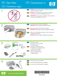
and highlights the function accessed in
reverse video. This informs the operator
which frequency or level parameter is then
available for control.
ONTROL " A ,,-,
...'~i.L"'",-,\"Mc:,,;":.'
('
.
Comprehensive
testingfacilitiesfor
Af-ll/FM/0M
transceivers
to 1000MHz
. Fullduplexfacilitytestsradio
telephonesandcross-band
repeaters
.
Sensitive receiver for off-air transmitter
monitoring with option 001
.
Built-inself test andoperatorguide
. Systemcheckingof simplex
transceiversin lessthan3 seconds
. OperationfromanystandardACsupply
upto 400Hzor vehiclesupply
. Sequentialandrevertivetones,DTMF
andDCSencoders/decoders
. Digital scopewith single shot for peak
modulation setting
. Menu driven CRTdisplay with 26 stores
for recall of standard settings
. GPIB
or RS232 for full instrument
.
Precisiondigitalreadoutsandautorangingbarchartsfor rapidtesting
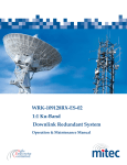
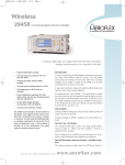
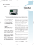
The 29558 Radio Communications Test
Set combines all the instruments required
for transceiver testing within a single unit.
Designed for bench and mobile field
service applications in maintenance workshops,
the instrument
is lightweight,
portable and may be operated from all
standard AC supplies, or vehicle supplies.
Comprehensive facilities are provided for
testing all types of AM, FM and 0M mobile
radio equipment, including low-power hand
portables and mobiles using selective
calling, full duplex radio telephones, digital
pocket pagers, base station and repeater
equipment.
Major
users
include
mobile
radio
manufacturers, providers of mobile radio
telephone networks, service maintenance
workshops, commercial and public service
organisations, and the military.
Comprehensive
Measurements
The 29558
comprises
19 instrument
functions for transceiver testing: RF power
meter, RF frequency meter, modulation
meter, RF signal generator, dual AF signal
generators, AF frequency meter, AF volt-
meter, 1 kHz AF distortion meter, SIN
74
.
control
HighstabilityOCXO
fittedas standard
and SINAO
meter,
sequential
tones
encoder/decoder,
OTMF encoder/decoder,
digitally
coded
squelch
(OGS)
encoder/decoder,
POGSAG digital pager
encoder and digital oscilloscope.
This
comprehensive instrument also functions
well as a low-cost ATE system, or as a
set of general-purpose test equipment for
production, service or laboratory use.
With option 001 the 29558 provides a
sensitive, selective input for measurement
of signals as low as 1 j1V.
Simple Set-up
Operation of the test set is by keys, which
configure the instrument functions to test
either a transmitter and receiver together
in full duplex mode, or independently for
simplex or semi-duplex operation. A large
GRT display provides the operator with
all generated and measured information
relating to a particular test, and a direct
indication of controls in use. Setting up the
instrument for a particular test involves
selection of the appropriate colour identified keys in a logicalleft-to-right sequence.
As the operator selects the required keys,
the screen indicates the test mode selected
"""
1""
\":!'*
Setting of specific test channel frequencies,
modulating levels and output levels etc.
is via a numeric key pad. However, for
convenience and speed of operation, three
variable controls are provided. Programmable incremental keys for frequency and
level allow the operator to define any
INC/DECrement size within the range
and resolution of the test set. This facility
enables rapid channel stepping for checking of multi-channel radios, and simplifies
receiver bandwidth and AGC testing.
For tests requiring fine adjustments of
frequency or level, such as squelch
threshold measurements or sub-audible
tone deviation settings, a rotary variable
control is available.
Large Clear Display
The CRT display provides the flexibility for
measurements to be presented in digital
form for precise unambiguous readings,
from which a hard-copy printout can be
obtained. It also allows measured information to be presented in analog bar chart
form, which is convenient for providing
adjustments such as simple peaking
indications. Comparative measurements
between positive and negative peak
deviation are available to check modulation
symmetry.
In transmitter, receiver and audio test
modes, a digital storage oscilloscope facility is provided. When testing transmitters,
the oscilloscope's vertical scale is
directly calibrated for modulation measurements: a single shot facility allows the user
to measure peak-to-peak modulation.
This peak hold function is invaluable for
setting the modulation limiter circuits
in the radio, and for ensuring that
maximum permissible deviation is not
exceeded.
TRANSMITTER TEST (MODE 'co Tx TEST)
When measuring a transmitter in the
frequency range 1.5 MHz to 1000 MHz, the
~
29558
modulation meter automatically tunes to
the incoming signal frequency in typically
less than 3 seconds, providing the user
with analog and digital readouts of all
parameters. This avoids the operator
having to set up the transmitter frequency.
The screen indicates transmitter frequency,
power. modulation frequency, modulation
level and transmitter distortion. All measurement scales are auto-ranging,
thus
preventing the likelihood of accidental
damage due to excessive input levels. Best
instrument measurement
accuracy
is
assured because manual range selection is
avoided: a range hold is available where
automatic ranging is not required. These
facilities cut service test time dramatically.
150 W Power Handling
RF power measurement range is 0.05 mW
to 75 W continuous rating, catering for
low-power portables and base station
transmitters. Power readings in dBm or
Watts are available. High-power transmitters of up to 150 W may be measured
for short intervals. A thermal sensor warns
the operator if the load gets too hot by
flashing a screen message to REMOVE
RF INPUT. A short interval later an
additional two-tone audible alarm is given
in case the operator's attention has been
diverted from the screen. To facilitate a
number of maximum power measurements, without having to wait for the power
load to cool, a HOLD DISPLAY key is
provided. This enables the user to freeze
the entire screen display after the readings
have stabilized, allowing all the transmitter
measurements and settings to be read,
with the transmitter de-keyed. A hard-copy
printout of all the digital information
contained in Rx, Tx, DUPLEX, AF TEST
and Directional Power meter screens can
be obtained using a GPIB or RS232
printer. The optional 24 column ticket
printer fits into the instrument lid for
storage.
sse Testing
RF frequency
counter
resolution
is
selectable as either 1 Hz or 10Hz enabling
tests of SSB systems. A two-tone modulating signal may be applied to a SSB
transmitter to check for linearity; the
carrier waveform may be observed at
the IF output socket on the rear of
the instrument. This facility also allows
future expansion in capability to meet
the needs of emerging radio telephone
networks.
Testing simplex radios is simplified by
using the Rx = Tx key. This pre-sets the RF
signal generator to the same frequency as
the transmitter, saving the operator the
task of entering the channel frequency in
receive test mode. The INC/DEC keys may
be used to offset the generator frequency
for channel-to-channel
operation or for
semi-duplex tests.
DUPLEX TEST i~~ODE " D!~IPLEY: TEf:;T)
Full duplex testing of radio telephones is
possible with all necessary parameters for
both the transmitter and receiver displayed
simultaneously on the CRT screen. The
frequency and level of the RF and AF
signal generators may be independently
controlled from the instrument key pad or
varied using the rotary control.
Any Duplex Offset
A standard feature is that the modulation
meter is independent of the RF signal
generator, so there is no restriction to the
total frequency offset between transmitter
and receiver test. This means that in
addition to measuring standard duplex systems, cross-band repeaters and repeater
systems using mixed AM and FM equipment can be tested.
RECE!VER TEST (MODE"" Ax TEST)
In the receiver test mode, standard
default settings of the RF and AF signal
generators are provided. The RF signal
generator level is set to -100 dBm and
the AF signal generator frequency to
1 kHz. Modulation can be set to any default
value for FM, 0M and AM testing within the
default limits. This facility is provided so
that the minimum amount of user interaction is required to perform a simple
system check after switch on. If the RF
signal generator frequency has been preset using the RX= TX key and the radio
being tested is simplex, then no further
instrument settings are required. For a
functioning receiver, audio output will be
present from the receiver under test.
Noise and Distortion
Dedicated keys allow the user to select
either signal-to-noise
(S/N) , SINAD or
distortion test. All readings are displayed
numerically on the CRT screen and as
auto-ranging bar charts for maximum user
convenience.
RF output level accuracy is specified
to be within :t2 dB over the attenuator
range of +5 dBm to -127 dBm, and
includes the effects of temperature, from
0 to +50°C, making the signal generator
one of the most accurate available in a test
set for the maintenance user.
Comprehensive
modulation control is
provided by using the INC/DECrement
keys or rotary control. The generator may
be internally or externally modulated to
produce AM, FM or 0M signals. The
external modulation input can be used for
dual tone inputs such as DTMF tones, or
for FFSK/FSK modulation.
AUDIO TEST (MODE = RxTESl
FUNCT!ON'" AF GFN)
The audio generator function provides
access to the 2 audio generators, AF
voltmeter and digital oscilloscope. The
audio generators provide a choice of
sine, square, triangular and saw-tooth
waveforms. Tone generation is available
providing CCIR, ZVEI, DZVEI, EEA, EIA
or USER DEFINED tones, and separately
DTMF generation
and decoding. The
AF input socket has a nominal input
impedance of 1 MQ, making it compatible
with standard probes.
TONES ENCODER'OECCJr!FP
The 29558 provides a very comprehensive
analog and digital tones encoder/decoder
facility for testing selective circuits in mobile
radios and digital pagers. Sequential tone
standards are available to the user from
a screen menu. In addition, a USER
DEFINED mode allows 15 different tone
frequencies to be defined. Provision is
made to send a sequence of up to 33 tones
in any standard, either as a single burst,
tone step or as continuous cycles for
receiver testing. Frequencies
may be
shifted from nominal up to :t9% in 1% steps
for tolerance checking of receiver decoders. Anyone of the sequence tones can
be extended. Sub audible tones (CTCSS)
and two tone operation are also available.
Standard Tones
Decoded
tones
are
compared
with
standard frequencies held in memory. If
each tone is within the standard limits, the
tone number, frequency and percentage
error is displayed. Sub audible tones are
measured directly in the transmitter test
mode by the audio frequency counter with
the 300 Hz low pass filter selected: this
allows measurement even in the presence
of modulation. For applications requiring
encoding and decoding of complex or non
standard tones systems, an EXTernal
MODulation input and AF DEMODulation
output are provided.
Revertive tone systems can be tested.
Up to 11 tones can be programmed for
transmit; with decoding and display of up to
11 revertive tones from the unit under test.
7~
~
--~~:J_~
-
'!~.~1
29558
Using
the
microphone
interface dissipated in the power load, and if a
accessory and microphone (54432-013E transmitter with an output power of up to
and 54412-020Y) it is possible to use 50 W is accidentally connected to the
the 29558 in a 'talk-through' mode as a BNC-RF connector, a relay opens the
low power transceiver for testing mobile signal path thus protecting the instrument.
equipment whilst in service. This allows
instructions to be given to the radio Simple Servicing
operator and for comments to be returned. A built-in self test facility identifies faulty
In this way large fleets can be quickly sections either to major module level or
group of components, so reducing the
tested, with minimum disruption to users.
The sensitive receiver allows channel mean time to repair. Instrument down-time
Pager Testing
and
frequency scanning. It is possible to is further reduced by modular construction,
POCSAG digitally coded pagers can be
which simplifies the service of faulty
tested with control of the pager frequency, store up to 11 spot frequencies or a modules. The Test Set has only six PCBs
channel
plan
of
up
to
9999
channels
in
bit rate, deviation and identity code.
plugging into a mother board, a plug-in RF
Transmission of either an alert signal only, memory. The 29558 may then be asked to
tray, an attenuator block, a receiver module
scan
until
a
signal
large
enough
to
lift
the
a numeric message or an alpha-numeric
(option 001) and a power load. These are
message is available. A facility to insert squelch is found. This is particularly useful
easily
removed for replacement or further
errors into the 32 bit address to test the where a base station is monitored.
--test.
unit's error correction capability is provided.
DTMF messages can be sent and
received, and displayed on the screen.
Digitally coded squelch (DCS) can be
generated with the capability to program the
DCS 3 digit code, digital bit rate, modulation
level and signal polarity. DCS transmissions
can be received,
decoded
and the
waveforms displayed with the correct code
highlighted from all possible codes.
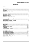
?:.~!J!':.r
l'l:""!.L!1t!!!
'In "O"F
TITLE
~ ~O"EO OF;
With option 001 fitted, off-air measure-
81 0" "E""ULl
820"
[)EF"ULT
ments of a transmitter station can be made
by the 2955B when Tx MONitor mode is
selected. A selective, sensitive receiver
with 1 /.lV sensitivity covering the range
100 kHz to 1 GHz is available to demodulate an off-air signal. Calibrated signal
strength is displayed in /.lV, mY, dBfJV or
dBm up to a level of 140 mY. Carrier
frequency is measured and displayed as
an offset from the ideal. Modulation level,
frequency and distortion are also displayed,
both as readings and as bar charts.
830"
84 H"
DEFAULT
DEF"ULT
[oEF"ULT
"CFAOJLT
DEF"ULI
Dcr"ULT
Off-Air Testing
In use the 2955B is connected to a suitable antenna or the telescopic antenna
supplied. The readings are then presented
in a similar way to the normal transmitter
test screen. The increment keys may be
used to alter the carrier frequency, such as
for channel steps, and the variable control
is available for fine tuning. The audio
generators are available for exciting the
transmitter, typically over a land line to a
remote base station. Other applications
include
the use of a probe
(see
52388-9000) for fault finding and aligning
receiver circuits such as mixers,
IF
amplifiers and filters. Being high impedance, the loading on the circuit in question
can be minimized.
The
demodulated
signal
can
be
monitored on the built-in loudspeaker and
on the storage oscilloscope display. If
desired an external loudspeaker or a
headset can also be used. To cater for
different modulation types, two receiver
bandwidths are available, 12 kHz for
narrowband speech and 180 kHz for
data and broadcast signals. The normal
transmitter tones decoding facilities are
available to permit tests on remote base
station calling tones.
76
",. 0"
060"
010"
88 H"
5TOOE5CDEFCHI.JKL"NOPQRST"l
VW"Y281234a.789/-.a!-J
I~~
I
~:r_T.!!~
r;ii~
-~~.:~
r;;Tr p-,:-
Routine calibration needs have been
kept to a minimum and calibration factors
stored in non-volatile memory may be
accessed with a secure access code from
the front panel key buttC'ns, or via the
GP!B, permitting rapid recalibration.
A 3 ye..;. l..lconditi;:'llal warranty is
provided in many territories.
-1.;:';'-
~
=
~"T~
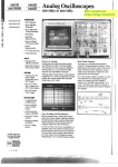
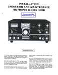
26 non-volatile ~tores are provided, each
capable .]1 . dtaining indefinitely a complete
front panel set-up, with instant recall
whenever required. Each store may be
allocated an alphanumeric title of up to 20
characters to remember its contents. One
additional storage location (00) provides
power fail back-up so that the last group of
front panel settings is restored after an AC
power or battery supply failure. A facility is
provided to lock the stores to prevent
accidental erasure.
Full instrument control is provided via
the GPIB or RS232 interfaces, and adds
further versatility for automatic testing, and
computer-assisted manual testing. A writeto-screen capability enables the CRT to
be used for operator instructions and for
simple straight line graphics. Specification
tests can be carried out using the upper
half of the screen, whilst the lower half is
used for drawing limit bar charts and
writing text.
Instrument lifetime is a significant factor in
cost-of-ownership, and the 29558 includes
a number of features to reduce calibration
costs, reduce down-time and help eliminate
expensive repairs. Visual and audible
warnings are given when excess power is
Accessories
are available
to provide
comprehensive cellular radio test facilities
for NMT, AMPS and TAGS. MPT 1327
(Band Ill) and similar trunked radio system
test facilities are also available.
Other accessories are described later in
this document.
FREQUENCY
Range
0.4 MHz to 1000 MHz (usableto 1060 MHz)
Resolution
50 Hz up to 530 MHz. 100 Hz up to 1000 MHz.
Indication
9 digit display.
Accuracy
As internalstandard.
OUTPUT LEVEL
Range
Rx Mode:
-135 dam to -15 dam (O.04jJVto 40 mV),
N-type socket selected.-15 dam to 5 dam
(0.4jJV to 400 mV), BNC socket selected.
One Port Duplex Mode:
-140dBmto-21.5dBm, (0.0224jJV to 18.85mV).
Two Port Duplex Mode:
-115 dam to -15 dam (O.04jJVto 40 mV).
Resolution
01 dB.
Indication
4 digits with unitsjJV, mV, dam, dBliV.
PO/EMFselectionas appropriate.
Accuracy
:,=1.8dB for levels above -127 dam, from +18 to +28'C.
:t2 dB from 0 to 50'C
29558
SPECTRAL
PURITY
Residual
FM
Lessthan13 Hz rms up to 520 MHz, typically 10 Hz;
lessthan26 Hz up to 1000 MHz,typically 20 Hz.
(300Hzto 3.4 kHz bandwidth).
Modulation range
0 to 10 fads.
Level Response
Resolution
0.025 rads. up to 63 rads.
01 fads, above 6.3 rads
Image Response
0 dB at :t428 MHz of RF input.
Typically:t3
Squelch
A manual squelch control is provided with a variable
threshold
Residual
AM
Lessthan0.5%(300 Hz to 3.4 kHz bandwidth).
Modulation frequency range
300 Hz to 34 kHz
Harmonics
Lessthan-20 dBc up to 1.5 MHz,
-25dBcupto 250 MHz,
-20dBcupto 1000 MHz.
Accuracy
:t8%at1 kHz,:t11%from300Hzt03.4kHz.
Sub-harmonics
Noneupto 530 MHz, less than -25 dBc to 1000 MHz.
Spurioussignals
Forcarrierfrequenciesup to B8 MHz:
Better
than-45 dBc up to 110 MHz, less than -35 dBc
above110MHz
Forcarrierfrequenciesup to 960 MHz:
Lessthan-60 dBc.
sse phasenoise at 20 kHz offset
Lessthan-110 dBc/Hz up to 500 MHz, less than
-104dBc/Hzto 1000 MHz.
RFleakage
Lessthan0.2 /lV PO generatedin a 50 Q load by a
2-tum25 mm loop as near as 25 mm to the case of the
instrument
with the output set to less than -40 dBm and
theoutputterminatedin a 50 Q sealed load.
Protection
50W reversepower trip, automaticallyresets on
removal01power input (BNC socket).
Visualalarmwarning (REMOVE
RFINPUT)and
audiblealanmprovidedfor added protection.
~M distortion
Less than 20/0at 1 kHz with 5 rads
(300 Hz to 34 kHz bandwidth).
FREQUENCY
EXTERNAL
As internal plus:
Resolution
1 Hzor 10 Hz to 200 MHz, 10 Hz from 200 MHz to
1000 MHz
AM Sensitivity
1 V p-p for 30% AM at 1 kHz:t15%reading:t1%AM.
FM Sensitivity
1 V p-p for 5 kHz deviation: :t10% at 1 kHz.
Modulation deviation range
0 to 30 kHz
~M Sensitivity
1 V p-p for 5 rads
:t12%at1kHz.
INPUT
WAVEFORM SHAPE
Sine,
square,
triangle,
saw-tooth.
FREQUENCY
Range
10 Hz to 20 kHz.
CWrange
15 to 400 MHz, usable from 400 kHz to 500 MHz.
Modulationdepth range
0to 99%.
Accuracy
:to.01
Hz
:1:0.1
Hz
from
from
Distortion
Less
than
50
to
Hz
10
100
0.5%
15
Hz
to
100
Hz
to
20
at 1 kHz
kHz
Residual
AM distortion
Lessthan 2% distor1ionat 1 kHz with 30% AM (300 Hz
to 34 kHz bandwidth).
OUTPUT LEVEL (EMF)
CW range
0.4 to 1000 MHz (usableto 1060 MHz).
Modulation deviation range
0 to 25 kHz.
Frequency range
As RF FrequencyMeter.
Hz.
kHz.
(sine),
less than
1% from
than
0.1
mV
RMS
in a psophometric
bandwidth.
offset
Less than 10 mV DC
Range
0.1 mV to 4.095
0.1 mV to 4095
V RMS
V peak
(sine and square).
(triangle and sawtooth).
dig~,
50
Hz
to
15
kHz.
Setting
0.1
mV
steps
(0.1
mVto
409.5
Accuracy
~.'%z10Hzat1 kHz.
z10% from 50 Hz to 15 kHz.
FM distortion
Less than 1% distortionat 1 kHz with 5 kHz deviation
(300 Hz to 3.4 kHz bandwidth).
PHASE MODULATION INTERNAL
CW range
0.4 to 1000 MHz.
Accuracy
:t10% :t1 digit up to 500 MHz,
:t15%:t1 digit up to 960 MHz,
:t2O%:t1 digit up to 1000 MHz,
:t25% typical BNC socket
mV).
1 mV steps (409.5 mV to 4.095 V).
Resolution
25 Hz «6.25 kHz dev.).
100 Hz «25 kHz dev)
Modulation frequency range
20 Hz to 20 kHz
Setting
Automatic rangingon scales with full scale values 30,
100,300 mW, 1,3,10,30,100 Wand 300 W.
VSWR
Less than 1.2 to 500 MHz,
less than 135 to 1000 MHz (N-type).
Less than 2.2 to 1000 MHz (BNC)
Accuracy
:1:5%:1:1
Resolution
1% full-scale
Indication
2/3 digits and analog display.
noise
Less
DC
Measurement Units
Watts or dBm
(sine).
Accuracy
:;7%of setting :;1 digit at 1 kHz up to 85% AM.
:;10%ofsetting:;1 digit, 50 Hz to 5 kHz up to 70% AM.
:;15%ofsetting:;1 digit, 50 Hz to 15 kHz up to
85%AM
FREQUENCY MODULATION INTERNAL
Range
0.05 mWto 150W.
Input to type-N socket:
50 mW to 75 W continuous,Tx Mode selected
100 mW to 75 W continuousin single port duplex mode
(150 W max for typically 2 minutesat 25°C
continuous)
End of safe working is indicatedby screen warning
"REMOVERF INPUT' and audible alarm.
Input to BNC socket:
Usable005 mW to 25 mW.
Less than 5 Q nominal.
Resolution
0.1 Hz (10 Hz to 3.25 kHz).
1 Hz (3.25 kHz to 20 kHz).
Modulationfrequency range
20 Hz to 20 kHz
INPUT
Accuracy
As internal standard :t1 digit.
VSWR
Lessthan 1.2 to 500 MHz, less than 1.3 to
1000MHz (N-type),less than 2.2 to 1000 MHz (BNC).
Resolution
10;0.
Typical acquisition
Up to 200 MHz, 100 ms, with 10Hz resolution;
1 s with 1 Hz resolution
Up to 1000 MHz, 400 ms.
Sensitivity
N type socket; 5 mW (0.5 V), Tx mode selected.
20 mW (1 V), one/two port duplex.
BNC input; 0.05 mW (50 mV); 1 jJV with option 001
fined
Modulation frequency range
1 Hz to 50 kHz.
OUTPUT IMPEDANCE
INTERNALAMPLITUDE MODULATION
Range
15 MHz to 1000 MHz (usable to 1060 MHz)
Input impedance
1 MQ in parallelwith approximately40pF.
OUTPUTIMPEDANCE
50Q nominal.
MODULATION
dB from 10 MHz to 1000 MHz.
FREQUENCY
Range
100 kHz to 1000 MHz (usable to 1060 MHz).
Sensitivity
2/lV for 10 dB SINAD in 12 kHz bandwidth from 1 MHz
to 1000 MHz for 3.5 kHz deviation in psophometric
bandwidth (typically 1 /lV).
Linearity Response
Typically:t3 dB level accuracy at 100 MHz with
reference to ~
dBm, over range -87 dBm to -24 dBm
(10/lVto 14 mV) BNC; -67 dBm to -4 dBm (100/lVto
140 mV) N type.
Manual tune
Providesfrequency
offsetindication
fromcarrier.
3 Digits and decimal point indicate most significant
positiveor negativeerror.
Auto-tune
Providesmeasurementand simultaneousdisplay of RF
frequency. power, modulationfrequencyand level, and
1 kHz demodulationdistortion.
Acquisition
Less than 3 seconds at 10 Hz resolution.
INPUT
Frequency range
As RF FrequencyMeter.
-
A..
-
29558
Sensitivity
As RF FrequencyMeter
AF filters
The followingfilters are available:
Bandpass- 300 Hz to 3.4 kHz,
Low pass - 300 Hz,
Low pass -15 kHz.
AMPLITUDE MODULATION
CW range
15 MHz to 400 MHz
Modulation range
Manualtune mode: 0 to 100% up to 400 MHz.
Auto-tune mode: 0 to 90% up to 100 MHz.
0 to 80% up to 400 MHz.
Auto ranging (bar chart), Oto 10, Oto 30, 0 to 100%
depth
Accuracy
;;5% :t1 digit at 1 kHz, :t8.5% ;;1 digit from 50 Hz to
10kHz.
Resolution
1%AM
Modulation frequency range
10Hzt015kHz
Demodulation distortion
Less than 2% above 21 MHz; Less than 5% below
21 MHz; measuredin a 300 Hz to 3.4 kHz filter and
30% AM at 1 kHz.
Residual AM
Less than 1% in a 300 Hz to 3.4 kHz bandwidthfor
inputs above 10 mW/0.1 mW (N-Type/BNC).
FREQUENCY MODULATION
Modulation range
0 to 25 kHz
Automaticranging (bar chart), 0 to 1,0 to 3, 0 to 10,
0 to 30 kHz.
Resolution
10 Hz up to 2.5 kHz deviation
1% up to 25 kHz deviation.
Accuracy
:t5% :t1 digit at 1 kHz, ;;7.5% over range 50 Hz to
10kHz
Modulation frequency range
10Hz to 15kHz.
Demodulation distortion
Less than 15% at 5 kHz deviation and 1 kHz
modulationfrequencyin a 300 Hz to 3.4 kHz
bandwidth
Residual FM
Lessthan 15 Hz RMS up to 500 MHz, typically 12 Hz
Less than 30 Hz RMS up to t 000 MHz, typically 24 Hz.
For inputs above 20 mW/0.2 mW (N-Type/BNC),
(300 Hz to 34 kHz bandwidth).
PHASE MODULATION
Modulation range
0 to 10 radians Automatic ranging (bar chart), 0 to 1,
Ot03andOt010radians.
Resolution
1% or 001 radians.
Accuracy
:,=5%:t1 digit at 1 kHz
:t7.5% :t1 digit from 0.3 to 34 kHz with respect to
750 IlS de-emphasis.
Modulation frequency range
300 Hz to 34 kHz Phase de-modulation is obtained
using 750 IlS de-emphasis.
Demodulation distortion
Less than 2% at 5 rads Modulated by 1 kHz measured
in 300 Hz to 34 kHz bandwidth.
Voltage range
10 mV/div to 20 V/div in a 1-2-5 sequence.
Sensitivity
50 mV (100 mV for 40 dB SINAD/S/N).
Accuracy
;;5%.
FM ranges
;;30,15,6,3,1.5 kHz deviationat ;;10% accuracy.
Frequency
1 kHz.
Range
0 to 10%, 0 to 30% distortion.
0M ranges
;;15,7.5,3,1.5radat;;10%aCCuracy
Resolution
0.1% distortion.
AM ranges
20, 10, 5%/div at ;;10% accuracy.
Accuracy
;;5% of reading ;;0.5% distortion.
Sweep rates
100 /ls/div to 5 S/divin 1-2-5 sequence,accuracy
lockedto internal standard.
Sensitivity
50 mV (100 mV for 1% distortion)
Trigger
Repetitiveor single-shotstorage
Features
AC + DC, or AC measurements.
Input impedance
1 M(1 in parallel with approximately 40 pF.
Frequency range
20 Hz to 50 kHz (or DC)
Level range
0 to 100 mV, Oto 300 mV, Oto 1, Ot03, Oto 10, Oto30
andOt0100V.
Tone decoder facilities
Displaystone number,frequencyand percentageerror.
Screen indicatesnull tones (using CRT) and annotates
out of limit frequenciesfor ease of identification.
Resolution
1 mV on 1% dependent on range
Accuracy
:t3% :t3 mV :t1 digit (50 Hz to 20 kHz or DC).
Frequency response
Switchable: bandpass 03 to 3.4 kHz, low pass 300 Hz
or 50 kHz, external filter
Range
20 Hz to 20 kHz
Tonesencodeanddecodefacilityavailableusing
AFGEN output and AF input 8NC sockets
Accuracy
As internal standard :t1 digit :to.1 Hz or 0.02%
(whicheveris greater).
Revertive tones
Available in Receive Test Mode, tones are sent to the
radio and the 29558 awaits a response.
Sensitivity
50mV.
.;':j~~LI~~~:.,..
DTMF ENCODER/DECODER
Provides DTMF encoder and decoder under Tones
menu. Tone duration and intertone gaps may be varied
from 10 to 999 ms in 1 ms steps.
~,:ijr:.1lJ~jr,-1;.::
OCXO
Oven controlledcrystal oscillator, nominalfrequency
10 MHz.
Temperature coefficient
Less than :t5 pans in 10' from 0 to 50.C;
Less than :t4 parts in 1o'rc from 50 to 70.C.
Ageing rate
Less than :t5 pans in 10"/month,:t2 pans in 10'/year
after 1 month's continuoususe
Short-term stability
Less than :t1 pan in 10', RMS frequency error over a
1 s period.
Retrace error
Less than :t2 parts in 10' over 24 hours, at constant
temperatureand after 25 minuteswarm-up
'~I..,~~T,1.
-~;ll":!-~cl~~~:,.,.j;-:.ir,1i~',W;1':
~~,I;II
Frequency
1 MHz
Level
100 mVt03 V AMS.
Impedance
Nominally 10 k~l in parallel with 100 pF.
Frequency
1 kHz
Range
0 to 18 dB, 0 to 50 dB (SINAD).
Oto 30. 010 100 dB (SIN).
Resolution
01 dB.
Accuracy
:t1 dB.
78
User defined
Allows definitionof up to 15 tones.
Frequencyrange 300 Hz to 34 kHz, duration 20 ms to
1.2 s (decode);20 Hz to 20 kHz, duration 10 ms to
999 ms (encode).Frequenciesare stored in nonvolatile memory A copy function allows any of the
tonestandards
to becopiedthenmodifiedinthe user
defined memory
Tones in audio mode
Resolution
0 1 Hz/1 Hz.
'JI~r;il!,-1.
Functions
Encodes33 tones, decodes up to 33 tones in a CCIR,
ZVEI, DZVEI, EEA, EIA or USER DEFINEDtone
sequence.
Tone encoder facilities
Send continuous,burst, single step, extend any tone,
null, repeat or frequency shift up to ~9% in 1% steps.
,.~I,c:Ilr,1~ ;-:ii~.:;lr,.1,c:~[~;,-j,.,~..,.];-:~.,~.~~i'
PAGER TESTER
Encoding of POCSAG code CCIR No 1 Rec. 584.
Bit rate 400-1500 bits/s, deviation 0-25 kHz
Allows entry of Radio Identity Code (RIC), 4 addresses,
2 preset numeric messages, 4 alphanumeric messages
and insertion of bit errors. A data Invert facility is
provided.
DCSENCODER
Digitally Coded Squelch encoder, allows entry of Bit
rate 100-200 bits/s, deviation 0-25 kHz. Polarity, normal
or inverted, RIG 3 digit code.
DCS DECODER
Displays bit rate, deviation, polarity and all possible
codes.
DEMODULATION OUTPUT SOCKET
Level
400 mV p-pfor;:1 kHz deviation ;:10%.
Impedance
10 k~1 nominal.
Bandwidth
Features
Single or repetitive sweep. available in Tx, Ax and
Audio Test modes (Tx MON with option 001), calibrated
for AM. FM and 0M
Frequency range
DC to 50 kHz (from 3 Hz on AC).
Either 300-34 kHz, 15 kHz or 300 Hz LP
EXTERNAL MODULATION
In Rx MOD, the 2955B can be configured to measure
the modulation at the EXT MOD INPUT Adjustment will
provide the desired modulation level.
29558
ACCESSORY
SOCKET
Pins3, 4, 5, 6 accessorycontrol.
Pin2, +12V, 100 mA max
Pin7,AF output,1 W into 8 t~.
Pin1,pulseou1pu1
availableunder GPIB control,
approximately
600 ns.
Rx = Tx FREQ
Presets
the RF signal generator frequency to the
measuredfrequency in Tx mode and Duplex mode.
Hold Display
Freezes instrument settings and readings, facil~ting
high RF power measurements and hard copy printout of
Tx, Ax, Duplex, Tx monitor or AF test screens.
J i
i
,
,i
1
~
INC/DEC
Available in Tx, Ax, Duplex, Tx monitor and AF test
modesfor defining frequency or level increments of the
AF and RF signal generators. Any step size setting
within the range and resolution of the test set is
pem1issible
Supply frequency
45 Hz-440 Hz
Maximum consumption
100 VA (with all options fitted).
DC supply consumption
Less than 70 W (with all options fitted).
GPIB INTERFACE
All functions except the supply switch are remotely
programmable.
RATED RANGE OF USE
0 to 50.C
Audible output
For listening to demodulated output and received audio.
Two tone modulation
In transmit mode, two tones are available under tones
menu in receiver mode, external modulation inputs add
to internal modulation
-
Supplied with
AC Supply Lead
Operating Manual.
Introductory Guide.
DC Supply Lead (with option 006).
BNC Telescopic Antenna
(with option 001).
Operating Summary Card.
RADIO FREQUENCY INTERFERENCE
Conforms with the requirements of EEC Directive
76/889 as to limits of RF interference. Complies with
VDE 0871, limit value Class B, as specified in General
Licence Vfg 1046/1964.
Recall00
Hold range
The displayed bar chart can be held, ie no autoranging,
by use of the oscilloscope pushbuttons.
Versions
Radio CommunicationTest Set with
GPIB interface.
Option 001 Sensitivereceiver.
Option 002 GPIB interface removed.
Option 003 RS-232fitted in place of GPIB
interface.
Option 004 FrenchVersion.
Option OOS SpanishVersion
Option 006 DC Kit & Front StowageCover.
Capabilities
Complies with the following subsets as defined in
IEEE 488-1978 and IEC Publication 625-1: SH1, AH1,
T5, L4, SR1, RL1, PPO, DT1, E1.
SAFETY
Complies with IEC 348.
Approved to UL 1244.
Help
Provides access to SELF TEST, stores lock, RF meter
resolution, SINAD or SIN default values, external
attenuator offset, variable default deviation,
2955/NORMAL emulation, default AF filter, Rx/Tx
modulation type lock, USNEurope tone standard
selection, and user help for Tx, Rx, Duplex and AF test
modes
Ordering
Numbers
29558
DC supply voltage
11-32 V DC
Store/Recall
26 non-volatile stores (01 to 26) are provided, each
capable of retaining all front panel settings for up to
10 years Alphanumeric titles are available for all store
locations
An additional store (00) is provided to retain the last test
set-up, in the event of a power fail.
VERSIONS AND ACCESSORIES
When ordering please quote eight digit code numbers.
range
Selected Accessories
Cellular and Trunking
UMIT RANGE
0 to 55.C
OF OPERATION
CONDITIONS
OF STORAGE
AND TRANSPORT
Temperature
-40 to +70.C
54415-0205
NMT Cellular Software'
TACS Cellular Software'
Band III (MPT 1327) Trunked
Radio Software'
* Fits into one of the above
Humidity
Up to 90% humidity.
Altitude
Up to 2500 m (pressurized freight at 27 kPa differential,
i.e. 39 Ibf/in').
DIMENSIONS AND WEIGHT
Height
Width
Depth
175mm
345mm
460mm
6.9in
13.6 in
18.1 in
Weight
15.5 kg (34lb)
16.8 kg (37Ib) with all options fitted.
54415-018W
54415-019D
i
converts a 2955B with GPIB to 2960B
to allow Cellular & Trunking.
NMT Cellular Software'
AMPS Cellular Software'
TACS Cellular Software'
Band III (MPT 1327) Trunked* Radio
Software
I Multi-cellular and trunking adapter
including D-AMPS, converts a 2955B
with GPIB to 2960D to allow Analog
Cellular and Trunking + D-AMPS.
46884-581G
46884-5835
46884-585D
I
adapters; at least one must be
selected at time of ordering.
Analog Amps Adapter - converts a
~955B with GPIB to 2957B to allow
Analog AMPS Cellular.
Digital Amps Adapter - converts a
2955B with GPIB to 2957D to allow
Analog and Digital AMPS Cellular
I
General Accessories
54421-003J
54421-002L
54462-o23W
POWER REQUIREMENTS
Rated supply voltage
105-120 VAG, 210-240 V AG, all :t100/o.
Multi-cellularand trunking adapter,
5441S-01SG
46884-101J
46884-102F
46884-103G
46884-1055
1
Adapters:
54211-001D
46883-877P
54433-002Y
54433-D04L
44991-1295
54411-0S2M
54499-042L
54499-043J
41690-60SY
46662-192W
54412-157G
46882-1148
RF DirectionalPower Head
25 MHz-1000 MHz
RF Directional Power Head
1 MHz-50 MHz
Battery Pack with built-in DC input
fast charger.
Printer 24 Column with Paper &
Ribbon.
Printer Ribbon & Paper Kit.
GPIB Interface.
RS-232 Interface.
PMRTEST Software
600 Q Balanced Interface with 20 dB
Attenuator.
CCITT Psophometric Filter.
CMESS PsophometriC Filter
Front Stowage Cover.
Hard Transit Case for 2955, 2957
and 2960 series.
Soft Carrying Case for 2955 series
Service Manual.
For further details of accessories please refer to the 2955
Series Accessories data sheet.
79