1
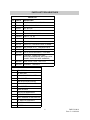
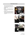
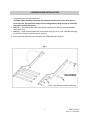
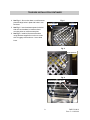
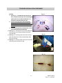
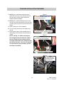
LEHMAN TRAMP TOUR BOX
INSTALLATION INSTRUCTIONS
LCK5093
PUB0011
2
PUB 751-0012
Rev. C—1/12/2012
SAFETY INFORMATION
UNDERSTANDING SAFETY LABELS & INSTRUCTIONS
READ AND BECOME FAMILIAR WITH ALL WARNING, CAUTION SYMBOLS AND STATEMENTS
LISTED BELOW AND IN THE TEXT OF THIS MANUAL BEFORE YOU BEGIN WORK.
DANGER, WARNINGS & CAUTION SYMBOLS
This is the safety alert symbol. When you see this
symbol on your machine or in this manual, be alert
to the potential for personal injury. Your safety is
involved!
WARNING
SAFETY ALERT WARNING indicates a potential hazard
that may result in severe injury or death to the operator, bystander or person (s) inspecting or servicing the vehicle.
CAUTION
Indicates a potential hazard that may result in minor personal injury or damage to the vehicle.
CAUTION
CAUTION indicates special precautions that must be taken
to avoid vehicle damage or property damage.
NOTE:
NOTE provides key information by clarifying instructions.
IMPORTANT:
IMPORTANT provides key reminders during disassembly,
assembly and inspection of components.
3
PUB 751-0012
Rev. C—1/12/2012
IMPORTANT INFORMATION
THIS TOUR BOX ASSEMBLY HAS BEEN DESIGNED FOR INSTALLATION ON THE INCLUDED LEHMAN LUGGAGE RACK
FOR TRAMP MODELS. TOUR BOX INSTALLATION PROCEDURES AND WARRANTY WILL NOT APPLY IF INSTALLED
ON A NON-LEHMAN LUGGAGE RACK.
CAUTION: WHEN TOUR BOX IS POWERED, AUTO-LOCK IS
ENABLED 10 SECONDS AFTER TOUR BOX LID IS CLOSED.
BE SURE TO REMOVE KEYS AND REMOTE FROM TOUR
BOX BEFORE CONNECTING TO POWER.
BE SURE TO READ MANUFACTURER’S INSTRUCTIONS
INCLUDED WITH TOUR BOX BEFORE PROCEEDING TO
INSTALLATION.
© 2009. All rights reserved.
Lehman Trikes® provides this publication as is without warranty of any kind, either expressed or implied. While every precaution has been
taken in the preparation of this manual, Lehman Trikes® assumes no responsibility for errors or omissions. Neither is any liability assumed
for damages resulting from the use of the information contained herein. Lehman Trikes® reserves the right to revise and improve its products
as it sees fit. This publication describes the state of this product at the time of its publication, and may not reflect the product in the future.
Lehman Trikes® is a registered trademark. All other brands and product names are trademarks or registered trademarks of their respective
4
PUB 751-0012
Rev. C—1/12/2012
PARTS LIST/TOOLS/SUPPLIES
PARTS LIST
QTY. PART #
DESCRIPTION
12
CB1084
SCR, BN, SK, .25-20 X 0.75, SS
4
CN3054
NUT, HX, .25-20, SS, 18.8
1
CN3111
NUT, NL 8-32
1
CS4051
SCR, PN, PH 8-32 X 1.00
3
CT1014
TIE, NYLON, BLACK, 5.5”
4
CW2006
WSH, FL, .25, SS
4
CW2041
WSH, LK, .25, SS
2
CW2090
WSH, FL, #8
2
HB1115
SIDEPLATE, LUGGAGE RACK, CHROME
4
MB1300
BAR, CROSS, 9 1/4”, LUGGAGE RACK
1
PUB0011 INSTALLATION INSTRUCTIONS, LCK5093
1
S001399
PLATE, REINFORCEMENT, TOUR BOX
1
S001401
TOUR BOX, TRAMP (INCLUDES
MOUNTING HARDWARE AND POSI-LOCK
CONNECTORS FOR WIRE HARNESS)
1
S001403
NAME PLATE, OVAL, 1.56 X 3.13
1
S001422
BACKREST, TOUR BOX
TOOLS REQUIRED
QTY.
DESCRIPTION
1
3/8” RATCHET
1
3/16” ALLEN HEAD SOCKET
1
4MM SOCKET
1
5MM ALLEN HEAD SOCKET
1
6MM ALLEN HEAD SOCKET
1
9MM SOCKET
1
13MM WRENCH
1
PHILLIPS SCREWDRIVER
1
TAPE MEASURE
1
PAINT MARKER OR EQUIVALENT
1
1/4” DRILL BIT AND DRILL
ELECTRICAL TAPE
LOCTITE 242
5
PUB 751-0012
Rev. C—1/12/2012
TRUNK HINGE STOP BOLT
NOTE: A trunk hinge stop bolt prevents
trunk lid from opening completely and contacting tour box.
1. See Fig. 1. Open trunk lid and locate trunk
hinges.
2. See Fig. 2. Look at right-side trunk hinge to
determine if you have a hinge stop bolt. If not,
complete step 3.
3. See Fig. 3. Install trunk hinge stop bolt through
the access hole on right side trunk hinge as
shown using (1) 8-32 x 1 screw (CS4051), (2)
#8 flat washers (CW2090), and (1) 8-32 Nylock
nut (CN3111).
Fig. 1
Locate trunk hinges
Fig. 2
Hinge stop bolt installed
Fig. 3
Install hinge stop bolt here
6
PUB 751-0012
Rev. C—1/12/2012
LUGGAGE RACK INSTALLATION
1. Temporarily remove stock grab handles.
CAUTION: When installing side plates, be extremely careful not to scratch body paint or
frame rail paint. Use protective cloth or foam to safeguard trike body and get an assistant’s
help while installing side plates.
2. See Fig. 1. Attach side plates (HB1115) and grab handles to trike using grab handle hardware.
Leave bolts loose.
3. See Fig. 1. Install cross bars (MB1300) to side plates using (8) 1/4-20 X 3/4” (CB1084) and apply
Loctite 242 to threads of bolts and tighten securely.
4. Ensure that side plates are level and tighten grab handle/side plate hardware.
Fig. 1
Use original grab
handle hardware
1/4-20 X 3/4” SS button head bolt (CB1084)
7
PUB 751-0012
Rev. C—1/12/2012
TOUR BOX INSTALLATION
Fig. 1
1. See Fig. 1. Remove passenger seat.
2. See Fig. 2. Remove operator seat.
3. See Fig. 3. Align reinforcement plate
(S001399) on luggage rack so that front mounting holes (spaced closer together) are between
1st and 2nd cross bars and rear mounting holes
(spaced further apart) are between 2nd and 3rd
cross bars.
Remove passenger seat
Fig. 2
Remove operator seat
Fig. 3
Front mounting holes
1
2
3
4
Rear mounting holes
8
PUB 751-0012
Rev. C—1/12/2012
TOUR BOX INSTALLATION CONTINUED
4. See Fig. 4. Set tour box base on reinforcement
plate and align holes in plate with holes in tour
box base.
5. See Fig. 5. Insert hardware spacers included
with tour box hardware in locations above
mounting holes on reinforcement plate.
6. See Fig. 6. Install reinforcement brackets
using hardware supplied in tour box to underside of luggage rack as shown. Leave bolts
loose.
Fig. 4
Tour box base
Align holes
Fig. 5
Insert spacers
Fig. 6
Reinforcement brackets
9
PUB 751-0012
Rev. C—1/12/2012
TOUR BOX INSTALLATION CONTINUED
7. See Fig. 8. Center tour box base creating equal
distances of 1 3/8” from edges of tour box base
and luggage rack side plates.
8. When base is centered, tighten mounting hardware.
9. See Fig. 9. Install tour box base cover included
with tour box by snapping into place. Remove
rubber pin cover from tour box base.
10. Install tour box on base by latching front section
first and pressing rear of tour box into place.
11. Route tour box wiring harness along inside of
right hand luggage rack side plate and toward
battery. Do not secure harness at this point.
NOTE: Wiring instructions reference a 2009
model unit. For 2008 and older models, be
sure to reference your OEM service manual
for specific wiring diagrams and use tour
box wiring diagram included with your tour
box.
12. See Fig. 10. Locate trike body wiring harness
on right side of battery (looking from rear) and
carefully remove heat shrink to expose wiring.
13. See Fig. 10-A. With heat shrink removed, locate brake light wire (white wire with black
stripe).
Fig. 8
Edge of tour box base
Luggage rack side plates
Fig. 9
Tour box base cover
Remove pin cover
Fig. 10
Remove heat shrink from wiring harness
Fig. 10-A
Locate brake light wire
10
PUB 751-0012
Rev. C—1/12/2012
TOUR BOX INSTALLATION CONTINUED
NOTES:
1. See Fig. 11. Included with tour box are (2blue, 2-red) Posi-lock taps for connecting to
power (be sure to read manufacturer’s instructions included with tour box).
2. Cover end of gray wire with heat shrink.
GRAY WIRE ON TOUR BOX BASE PLATE IS
NOT USED. One red Posi-lock tap will not
be used.
3. Use dielectric grease (included with connectors) with all Posi-lock terminals.
14. See Fig. 12. Connect blue wire to trike brake light
wire (red wire on trike body harness) using blue
Posi-lock tap).
15. See Fig. 12. Connect green wire to trike running
light wire (blue wire on trike body harness) using
blue Posi-lock tap.
16. See Fig. 13. Connect yellow wire to tour box plate
yellow wire with red Posi-lock tap.
Fig. 11
Fig. 12
Fig. 13
11
PUB 751-0012
Rev. C—1/12/2012
TOUR BOX INSTALLATION CONTINUED
17. See Fig. 14. Install black extension wire to
black wire from top tour box harness with red
Posi-lock tap. Connect eyelet connector to
negative terminal of battery.
18. See Fig. 15. Install red extension wire to red
wire from tour box harness with in-line fuse cap.
Connect eyelet connector to positive terminal of
battery.
19. Insert 3-amp fuse in fuse receptacle.
20. Turn on power and test tour box lighting and
remote.
21. Using electrical tape, cover exposed wires on
body wiring harness where heat shrink was removed.
NOTE: See Fig. 16. Before securing tour
box wiring harness with cable ties, adjust
tour box wiring harness sheath to ensure
coverage of exposed wires coming from bottom of tour box base. Also, be sure harness
isn’t positioned to get pinched by operator
seat when re-installed.
Fig. 14
1. Connect red cap to black wire of
tour box wiring harness.
2. Connect eyelet to negative terminal
Fig. 15
1. Connect in-line fuse cap to red
wire of tour box wiring harness.
Red
2. Connect eyelet to positive terminal
Fig. 16
Adjust sheath to
ensure wires are
not exposed
12
PUB 751-0012
Rev. C—1/12/2012
TOUR BOX INSTALLATION CONTINUED
22. See Fig. 17. Secure tour box wiring harness by
installing cable ties (CT1014) as shown.
23. See Fig. 18. Place tour box back rest template
included with tour box as shown on front of tour
box.
24. See Fig. 17. Using a paint marker or equivalent,
mark hole locations on tour box as shown.
25. Drill (2) 1/4” holes through tour box.
26. See Fig. 19. Install tour box back rest (S001422)
with hardware included in tour box.
27. Install oval Lehman badge on top of tour box lid.
28. Install tour box liners with Velcro patches (included
with tour box).
29. Reinstall operator seat. Be sure tour box wiring
harness is not pinched during re-installation.
30. Reinstall passenger seat.
Fig. 17
Secure wiring harness with cable ties
Fig. 18
Mark hole locations
Fig. 19
Install tour box back rest
13
PUB 751-0012
Rev. C—1/12/2012