1
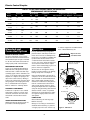
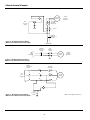
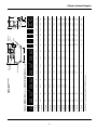
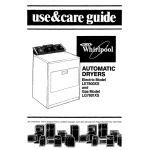
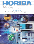
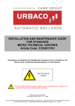
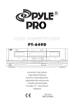
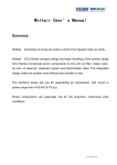
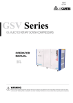
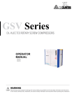
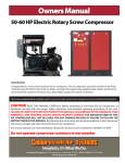
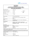
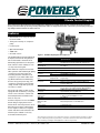
Climate Control Simplex
Please read and save these instructions. Read carefully before attempting to assemble, install, operate or maintain the product described.
Protect yourself and others by observing all safety information. Failure to comply with instructions could result in personal injury and/or property damage! Retain instructions for future reference.
Features
• Guaranteed low oil carryover rate of
less than 2 PPM
• Three year warranty on compressor
pump
• Isolation pads
• Optional R134 dryer
• ASME tank
• UL listed controls
The AS-XXX Series Powerex Simplex Air
Compressors have been designed, broken-in and tested to meet the most
demanding specifications in the pneumatic climate control industry for low
oil carryover and long life.
All Powerex air compressors have reliable operation and feature high quality
construction and components. An
unloading feature is included on all
compressors to provide loadless starting. Oil entrainment is minimized by
the use of lap joint piston rings, low
compressor speeds and a special lubricating oil with a high flash point and
low carbon content.
All 1/2 through 10 hp models are also
equipped with an auxiliary cooling fan
and air control shroud to achieve low
head temperatures and further minimize oil carryover.
Powerex compressor motors are NEMA
Class B design. Single-phase motors
have built-in overload protection and a
DPST disconnect switch. Three-phase
motors require a manual or magnetic
starter and three overload heater coils
which may be ordered as a factory
mounted and wired option.
Figure 1 - AS-XXX 1 Hp Simplex Air Compressor
Specifications
Product
Performance
Specifications
Models & Options
Lubrication
Operating
Voltages
Compression
Cycle
Motor Overload
Protection
Pressure Settings
Overpressure
Protection
Outlet Air
Connections
Tank Sizes
California
Ordinance 462
(L) (2)
Tank Isolation
Manuals
AS-XXX Series Powerex Simplex Air Compressors
1/2 Through 10
1Ø
3Ø
1/2 Through
10 Hp Models
1Ø
3Ø
See Table 1
See Table 2
Splash Lubrication System
115 - 208/230 Volts, 60 Hz
208-230/460 Volts, 60 Hz
Single-Stage
Built-In Thermal Overload (Standard)
Magnetic Starter and Three Thermal Overload
Switches (Optional)
Cut-In: Factory Set at Approximately 70 psig (490kPa)
Cut-out: Factory Set at Approximately 90 psig (630 kPa)
ASME Safety Valve Factory Set and Sealed at
Approximately 115 psig (805 kPa)
1/2" NPT on 30, 60 and 80 Gallon Tanks;
1" NPT on 120 and 200 Gallon Tanks
See Table 2
Meets Requirements of this Ordinance
Standard All Units
200 Page Service Manual Available
The performance specifications are nominal and conform to acceptable industry standards. For application at conditions beyond these specifications, consult the local Powerex office. Powerex shall not be
liable for damages resulting from misapplication or misuse of its products.
Powerex • 150 Production Drive • Harrison, OH 45030 • USA
IN259601AV 10/04
Climate Control Simplex
TABLE 1: AS-XXX SERIES POWEREX SIMPLEX AIR COMPRESSORS
PERFORMANCE SPECIFICATIONS
Base
Model
Actual Hp
1Ø
3Ø
Motor Rating
Hp
RPM
AS-105
.54
—
AS-005
—
.54
—
AS-107
.73
—
AS-007
—
.73
AS-110
1.07
—
—
AS-010
—
1.07
1.07
AS-015
—
1.54
AS-020
—
2.0
AS-030
—
AS-050
—
AS-075
—
AS-100
—
Compressor
RPM
1725
Compressor Capacity ACFM*
100% Runtime 50% Runtime 33% Runtime
800
1.8
0.9
0.6
1725
1040
2.5
1.25
0.83
1725
625
3.8
1.9
1.25
1.54
1750
955
6.4
3.2
2.11
2.0
1750
800
8.6
4.3
2.84
3.1
3.1
1745
775
12.0
6.0
4.0
5.6
5.6
1745
690
22.0
11.0
7.33
8.2
8.2
1745
795
28.5
14.3
10.3
10.3
1750
685
43.0
21.5
.54
—
.73
Mounted and
Connected Options
MAGNETIC MOTOR STARTER
An optional magnetic motor starter
which has been selected and wired for
the intended input voltage is available
for all units. All starters are furnished
with properly sized overload heaters.
REFRIGERATED AIR DRYER
A factory mounted Model Hankinson
HPR 5-10 Series refrigerated air dryer
with automatic condensate drain trap
assembly, bypass valve is available as an
option on all 1/2 through 3 Hp Powerex
Simplex air compressors. Piping for air
dryer is done at the factory. Wiring to
power source must be done in the field
using integral cord and plug which fits
into a standard 120 volt receptacle.
Refer to Table 2 for ordering details.
AUTOMATIC TANK DRAIN
Powerex air compressors are ordered
with either a manual or electric type
automatic tank drain. This unit is furnished with a manual drain attachment.
VIBRATION DAMPENING PADS
Waffle type design vibration pads are
provided as standard equipment.
1720
9.44
14.2
to release trapped air. Use Mobil Rarus
427® or Mobil DTE heavy oils.
Operation
Factory calibrated snap-acting DPST
pressure electric switches provide automatic cut-in and cut-out. Overpressure
protection is provided by an ASME safety relief valve. Receiver tanks have a
condensate drain valve with an extension for easy access. All mounting bases
are slotted for V-belt tension adjustment to aid in maintaining proper compressor and motor alignment.
! WARNING
Dispose of oil in
accordance with
state or local codes.
Remove cap and use
funnel to add oil.
All units are run through the factory
break-in and are tested for air delivery,
leakage and power consumption.
Units are shipped with a proper fill of
compressor oil in the crankcase and are
furnished with an intake filter/silencer
with a replaceable cartridge. This filter/silencer combination is designed to
remove contaminates in the inlet air
and provide quieter operation. The 5
through 10 Hp models are complimented by this design utilizing dual element
filtration which consists of a pleated
element and a foam element for filtration against larger particles from the
atmosphere.
Oil drain
cap
Oil gauge
Round (red)
Full
LUBRICATION
Check lubricating oil level at gauge.
Refill if necessary.
Change oil according to maintenance
schedule. Before draining oil, remove
oil supply cap and loosen oil drain cap
2
Low
OIL GAUGE
Figure 2 - Lubrication
Climate Control Simplex
AUTO E-DRAIN ASSEMBLY (See
Figure 3)
NOTE: The automatic E-drain is assembled to tank.
1. Plug E-drain into 115V power outlet
supply.
2. Adjust times accordingly.
Manifold
Assembly
TEST
ON
OFF
6
4
20
2
8
30
10
40
5
0.5
10
0.5
sec.
45
min.
Figure 3 - Auto E-Drain
r&
we ase
o
p
h
rse e P
Ho ltag
Vo
ize
kS
n
Ta
}
TABLE 2: MODEL NUMBER
AS
r
ye
nk n/Dr
a
T rai
D
r
te
ar
St
OR
105 =
107 =
110 =
NA =
NA =
NA =
NA =
NA =
NA =
1/2
3/4
1
11⁄2
2
3
5
71⁄2
10
= 005
= 007
= 010
= 015
= 020
= 030
= 050
= 075
= 100
NA = Not Available
Example 2: To order a Simplex air compressor with a
10 Hp three-phase motor, 200 gallon tank and an
auto drain, use product code AS-100-502.
Available on:
1/2 Through 1 ⁄2 Hp
3/4 Through 2 Hp
2 Through 71⁄2 Hp
5 Through 10 Hp
71⁄2 and 10 Hp
30 = 1
60 = 2
80 = 3
120 = 4
200 = 5
1
Starter Options
None = 0
3Ø, 208V Starter* = 2
3Ø, 208/230V Starter** = 3
3Ø, 460V Starter = 4
1Ø, 115V Starter = 5
1 Ø, 208/230 V Starter = 6
}
Example 1: To order a Simplex air compressor with a
3/4 Hp single-phase motor, 60 gallon tank, singlephase 115 volt starter, automatic tank drain and an
air dryer, use product code AS-107-254.
Tank Drain/Dryer Options
Tank Size
(Gallons)
1Ø vs 3 Ø selection must agree with
base model selection.
**This starter selection is dual
rated. Choosing digit “3”
means 230 V.
3
}
Motor Horsepower, Voltage Phase
1Ø
Horsepower
3Ø
Manual Drain,
No Dryer
E-Drain,
No Dryer
Manual Drain,
with Dryer
E-Drain,
with Dryer
Available on
1/2 through 3 Hp
models only.
=1
=2
=3
=4
Climate Control Simplex
* With
Integral
Overload
*Comp.
Motor
m
Secondary
Thermal
Overloads
N.C.
Pressure
Switch
m
m
Starter
Manual
Disconnect
Switch
Figure 4 - AS-XXX Single-Phase Wiring
With Pressure Switch Used for Pilot Duty
1Ø 230 VAC
Manual
Disconnect
Switch
N.C.
Pressure
Switch
1Ø
Line
Voltage
*Comp.
Motor
* With
Integral
Overload
Figure 5 - AS-XXX Single-Phase Wiring
With Pressure Switch Used as Contactor
Manual
Disconnect
Switch
Thermal
Overloads
M
3Ø
Line
Voltage
O.L.
M
*Comp.
Motor
M
M
Figure 6 - AS-XXX Three-Phase Wiring
With Pressure Switch Used for Pilot Duty
N.C.
Pressure
Switch
NOTE: “M” = Magnetic Contactor
4
Discharge
Optional
Dryer
5
50 3⁄4
64
65
65 1⁄2
AS-020-3XX
AS-030-3XX
79 ⁄4
70 3⁄4
81 3⁄4
79
81 ⁄4
AS-075-4XX
AS-075-5XX
AS-100-4XX
AS-100-5XX
1
81 1⁄2
70 3⁄4
64
3
—
—
—
—
—
—
—
66 23⁄32
—
—
—
—
—
—
—
66
66
66 ⁄32
23
52 3⁄4
52 ⁄4
42
52 3⁄4
42
52 3⁄4
42
42
w/o Starter
w/Dryer
52 19⁄32
51 ⁄32
27
43 1⁄32
51 27⁄32
43 19⁄32
51 27⁄32
43 19⁄32
43 19⁄32
w/Starter
and Dryer
B
30
27 1⁄4
30
26 1⁄4
23 1⁄4
26 1⁄4
30
24
30
24
20
24
20
23 ⁄4
1
20
20
20
20
17 3⁄4
20
17 3⁄4
20
17 3⁄4
17 3⁄4
23 1⁄4
23 ⁄4
1
23 1⁄4
22 ⁄4
1
21 1⁄4
22 1⁄4
21 1⁄4
22 1⁄4
21 1⁄4
21 1⁄4
w/Starter w/o Starter
w/o Dryer or Dryer
*Inches x 2.54 = Centimeters, Pounds x 0.454 = Kilograms
**Add 60.0 lbs. for units equipped with a factory mounted air dryer
3
76 1⁄2
64
AS-075-3XX
70 3⁄4
64
64
70 3⁄4
AS-050-3XX
AS-050-4XX
64
50 ⁄4
50 ⁄4
51 1⁄2
AS-015-2XX
AS-020-2XX
3
50 3⁄4
40
50 3⁄4
40
40
40
3
A
w/o Starter
or Dryer
42 1⁄2
50 3⁄4
42 1⁄2
50 3⁄4
42 1⁄2
42 1⁄2
w/Starter
w/oDryer
AS-015-1XX
AS-010-2XX
AS-110-2XX
AS-010-1XX
AS-110-1XX
AS-007-2XX
AS-107-2XX
AS-007-1XX
AS-107-1XX
AS-005-1XX
AS-105-1XX
Base
Model
TABLE 3: DIMENSIONS (Inches*) AND SHIPPING WEIGHTS (Pounds*)
Figure 7 - Dimensions
(See Table 3)
—
—
—
—
—
—
—
23 5⁄16
23 ⁄16
5
23 5⁄16
22 ⁄16
5
21 13⁄16
22 5⁄16
21 13⁄16
22 5⁄16
21 13⁄16
21 13⁄16
w/Starter
and Dryer
—
—
—
—
—
—
—
21
21
21
21
18 3⁄4
21
18 3⁄4
21
18 3⁄4
18 3⁄4
w/o Starter
w/Dryer
D
A
58
51
55 1⁄2
49 1⁄4
46
49 1⁄4
46
41
41
42
40
36
40
36
40
36
35 1⁄2
C
3
42
42
42
42
43 3⁄4
42
43 ⁄4
40
40
29
29
18
29
18
29
18
18
D
Plug
Optional
Starter
1
18 ⁄2
22
22
22
22
18 1⁄2
22
1
18 1⁄2
18 ⁄2
18
18
15 3⁄4
18
15 3⁄4
18
15 3⁄4
15 3⁄4
E
18 ⁄4
3
15 3⁄4
18 3⁄4
15 3⁄4
13
15 3⁄4
13
13
13
14
14
12 1⁄4
14
12 1⁄4
14
12 1⁄4
12 1⁄4
F
1141
915
951
725
621
714
609
509
384
349
349
219
349
219
339
209
209
1130
904
940
714
610
705
600
500
375
340
340
210
340
210
330
200
200
with
without
Starter Starter
F
C
Shipping Weight**
E
B
Climate Control Simplex
Climate Control Simplex
A
L
M
E
(Inside Belt Guard)
F
(Inside Belt Guard)
D
J
B
C
G
K
N
H
REPLACEMENT PARTS LIST
Item
A
B
C
D
E
Quantity
Required
Description
PUMP AND FLYWHEEL:
Motor Hp
1/2, 3/4
1
1, 11⁄2
1
2
1
3
1
5
1
1
7 ⁄2
1
10
1
VALVE KIT: Includes valve plate, spacer and head gasket
Motor Hp
1/2
1
3/4
1
1
1, 1 ⁄2
1
2
2
3
2
5
2
1
7 ⁄2
2
10
3
RING/CYLINDER KIT: Includes all compression rings, oil control rings, cylinder, gasket and sealant
Motor Hp
1/2
1
3/4
1
1
1, 1 ⁄2
1
2
2
3
2
5
2
1
7 ⁄2
2
10
3
INTAKE FILTER ELEMENT:
1/2
1
Motor Hp
3/4
1
1, 11⁄2
1
2
1
3
1
5
2
1
7 ⁄2
2
10
3
BELT:
Motor Hp
Size
1/2
AX-42
1
3/4
AX-42
1
1
A-43
1
11⁄2
A-46
1
2
A-65
1
3
A-62
1
5
A-65
2
71⁄2 (120 gal tank) A-67
2
71⁄2 (200 gal tank) A-75
2
10
A-84
2
6
Shipping
Weight
(lbs.)
Code
Number
19.5
35
59
66
115
121
180
A-005-6001
A-010-6001NP
A-020-6001NP
A-030-6001NP
A-050-6001NP
A-075-6001NP
A-100-6001NP
0.4
0.4
0.5
0.5
0.7
1.2
1.2
1.2
A-005-6002
A-005-6002
A-010-6002NP
A-010-6002NP
A-030-6002NP
A-050-6002NP
A-075-6002NP
A-075-6002NP
3.6
3.6
4.8
4.8
5.5
10
10
10
A-005-6004
A-005-6004
A-010-6004NP
A-010-6004NP
A-030-6004NP
A-050-6004NP
A-075-6004NP
A-075-6004NP
0.1
0.1
0.2
0.2
0.2
0.2
0.2
0.2
A-005-6023
A-005-6023
A-010-6023NP
A-030-6023NP
A-030-6023NP
A-030-6023NP
A-030-6023NP
A-030-6023NP
0.3
0.3
0.3
0.3
0.4
0.4
1.6
2.0
2.0
2.4
A-005-6006
A-005-6006
A-010-6006
A-015-6006NP
A-020-6006NP
A-030-6006NP
A-050-6006NP
A-075-6046NP
A-075-6056NP
A-100-6006NP
Climate Control Simplex
REPLACEMENT PARTS LIST (Continued)
Item
F
G
H
J
Quantity
Required
Description
MOTOR PULLEY:
Motor Hp
Type
1/2
1A-4.4” P.D., 5/8” Bore
3/4
1A-5.8” P.D., 5/8” Bore
1 (1 Ø)
1A-4.0” P.D., 5/8” Bore
1 (3 Ø)
1A-4.0” P.D., 7/8” Bore
11⁄2
1A-6.0” P.D., 7/8” Bore
2
1A-6.0” P.D., 7/8” Bore
3
1A-6.0” P.D., 11⁄8” Bore
5
2A-5.6” P.D., 11⁄8” Bore
71⁄2
2A-7.6” P.D., 13⁄8” Bore
10
2A-7.6” P.D., 15⁄8” Bore
IN-TANK CHECK VALVE:
Motor Hp
Size
1/2 Through 3
1/2” MPT x 1/2” FPT
5 Through 10
3/4” MPT x 3/4” FPT
SAFETY RELIEF VALVE: Set at approximately 115 psig (805 kPa)
1/2 Through 5 Hp Models
71⁄2 Through 10 Hp Models
PRESSURE ELECTRIC SWITCHES: (For all models)
Lead Switch: Set at approximately
70 psig (490 kPa) cut-in and
90 psig (630 kPa) cut-out
Shipping
Weight
(lbs.)
Code
Number
1
1
1
1
1
1
1
1
1
1
3.8
3.9
3.2
3.2
5.6
5.2
6.3
7.6
12.5
13.5
A-005-6007
A-007-6037
A-110-6007
A-010-6007
A-020-6007
A-020-6007
A-030-6007NP
A-050-6007NP
A-075-6007NP
A-100-6007NP
1
1
0.3
0.4
A-010-6008
A-075-6008
1
1
0.1
0.2
A-050-6009
A-200-6009
1
0.9
A-100-6010
Lag Switch: Set at approximately
60 psig (420 kPa) cut-in and
80 psig (560kPa) cut-out
1
0.9
A-100-6011
K
TANK:
Motor Hp
Tank Size
1/2 Through 11⁄2
30 gallon
1
134.0
A-010-6030NP**
1/2 Through 11⁄2
60 gallon
1
175.0
A-010-6060NP
2&3
60 gallon
1
184.0
A-020-6060NP
1
1/2 Through 1 ⁄2
80 gallon
1
235.0
A-010-6080NP**
2&3
80 gallon
1
243.0
A-020-6080NP**
2&3
120 gallon
1
398.0
A-020-6120NP**
1
5 & 7 ⁄2
120 gallon
1
415.0
A-050-6120NP**
5 Through 10
200 gallon
1
677.0
A-100-6200NP**
L
COOLING SHROUD:
Motor Hp
1/2
1
1.0
A-005-6013
3/4
1
1.0
A-005-6013
2
1
1.7
A-020-6013NP
3
1
1.7
A-030-6013NP
5
1
1.9
A-050-6013NP
71⁄2
1
1.9
A-075-6013NP
10
1
4.5
A-100-6013NP
M
BELT GUARD:
Motor Hp
1/2 Through 11⁄2
1
2.4
A-010-6012
2&3
1
12.5
A-020-6012
5 & 71⁄2
1
12.5
A-050-6012
10
1
18.5
A-100-6012
N
LIQUID GASKET:
Motor Hp
1/2 Through 10
1
0.1
A-999-6000
**This replacement tank is also the replacement tank used on duplex air compressors and will include mounting hardware for a second pump.
7
Climate Control Simplex
Maintenance Schedule
Item
Action needed
500
2500
Tank
Inlet air filter
Blower fan
Fan duct
Compressor fins
Oil change
Compression rings
Check oil
Piston set
V-belt
Pressure switch
Magnetic starter
Drain moisture
Replace
Clean
Clean
Clean
Replace
Replace
Inspect
Replace
Inspect, replace
Confirm operation
Inspect
Daily
2500
Operating Hours
5000
10,000
15,000
(Every 2,500 hrs or less)
(Every 2,500 hrs or less)
(Every 1,500 hrs)
20,000
Remarks
Daily
*Note 3
Replace if contact
points deteriorated
Safety valve
Confirm operation
(Every 2,500 hrs or less)
Pressure gauge
Inspect
(Every 2,500 hrs or less)
() Inspect
() Replace
NOTES:
1. Inspect and perform maintenance periodically according to maintenance schedule.
2. The maintenance schedule relates to the normal operating conditions. If the circumstances and load condition are adverse, shorten the
cycle time and do maintenance accordingly.
3. * The tension of the V-belt should be adjusted during initial start up and inspected every 1,500 hours afterwards. Proper belt tension for
1/2 to 3 HP units is 2-3 lbs./.5” deflection; for 5 to 10 Hp units, 4-6 lbs./.5” deflection.
Powerex Limited Warranty
Powerex 3 Year / 10,000 Hour Extended Parts Limited Warranty - Powerex warrants each Compressor Pump or Scroll Air-End
against defects in material or workmanship from the date of purchase for a period of Three years or 10,000 hours, whichever may
occur first. This warranty applies to the exchange of part(s) of the compressor pump or air-end found to be defective by an Authorized
Powerex Service Center.
Powerex 1 Year / 5,000 Hour Inlet to Outlet Limited Warranty - Powerex warrants each Compressor Unit, System, Pump, or AirEnd against defects in material or workmanship from the date of purchase for a period of One Year or 5,000 Hours, whichever may
occur first. This warranty applies to the exchange of defective component part(s) and labor performed by an Authorized Powerex
Service Center.
The above mentioned warranty applies to POWEREX manufactured units or systems only.
Items listed in the operator’s manual under routine maintenance are not covered by
this or any other warranty.
THERE IS NO OTHER EXPRESS WARRANTY. IMPLIED WARRANTIES, INCLUDING THOSE OF MERCHANTABILITY AND FITNESS FOR A PARTICULAR PURPOSE, ARE LIMITED TO ONE YEAR FROM THE DATE OF PURCHASE: AND TO THE EXTENT PERMITTED BY LAW, ANY AND
ALL IMPLIED WARRANTIES ARE EXCLUDED. THIS IS THE EXCLUSIVE REMEDY AND LIABILITY FOR CONSEQUENTIAL DAMAGES UNDER
ANY AND ALL WARRANTIES IS EXCLUDED TO THE EXTENT EXCLUSION IS PERMITTED BY LAW.
All claims pertaining to the merchandise in this schedule, with the exception of warranty claims, must be filed with POWEREX within 6
months of the invoice date, or they will not be honored. Prices, discounts and terms are subject to change without notice or as stipulated in specific product quotations. All agreements are contingent upon strikes, accidents, or other causes beyond our control. All shipments are carefully inspected and counted before leaving the factory. Please inspect carefully any receipt of merchandise noting any
discrepancy or damage on the carrier’s freight bill at the time of delivery. Discrepancies or damage which obviously occurred in transit
are the carrier’s responsibility and related claims should be made promptly directly to the carrier. Returned merchandise will not be
accepted without prior written authorization by POWEREX and deductions from invoices for shortage or damage claims will not be
allowed. UNLESS OTHERWISE AGREED TO IN WRITING, THESE TERMS AND CONDITIONS WILL CONTROL IN ANY TRANSACTION
WITH POWEREX any different or conflicting terms as may appear on any order form now or later submitted by the buyer. All orders
are subject to acceptance by POWEREX.
150 Production Drive
Harrison, OH 45030
Phone: 1-888-769-7979
Fax: 513-367-3125
8