1
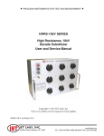
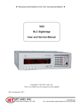
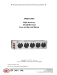
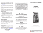
♦ PRECISION INSTRUMENTS FOR TEST AND MEASUREMENT ♦
HACS-Z-A-7E-1pF
Decade Capacitance System
User and Service Manual
Copyright © 2010 IET Labs, Inc.
Visit www.ietlabs.com for manual revision updates
HACS-Z-A-7E-1pF im/April 2010
IET LABS, INC.
Long Island, NY • Email: info@ietlabs.com
www.ietlabs.com
TEL: (516) 334-5959 • (800) 899-8438 • FAX: (516) 334-5988
♦ PRECISION INSTRUMENTS FOR TEST AND MEASUREMENT ♦
IET LABS, INC.
Long Island, NY • Email: info@ietlabs.com
www.ietlabs.com
TEL: (516) 334-5959 • (800) 899-8438 • FAX: (516) 334-5988
HACS-Z-A-7E-1pF
Contents
Chapter 1 Introduction...............................................................................1
1.1 General Description............................................................................................... 1
1.2 Switches................................................................................................................. 2
1.3 Double Shielded Construction............................................................................... 2
Chapter 2 Specifications............................................................................3
Specifications ................................................................................................................. 3
Double Shielded Construction ....................................................................................... 3
Chapter 3 Operation...................................................................................5
3.1 Initial Inspection and Setup................................................................................... 5
3.2 Switch Setting........................................................................................................ 5
3.3 Connection to Terminals........................................................................................ 5
Chapter 4
Maintenance..........................................................................................7
4.1 Preventive Maintenance......................................................................................... 7
4.2 Calibration Interval................................................................................................ 7
4.3 Considerations for Calibration............................................................................... 7
4.4 Calibration Procedure............................................................................................ 8
4.5 Capacitance Adjustment......................................................................................... 8
4.5.1 Adjusting 1 pF - 1,000 pF decades.............................................................. 8
4.5.2 Adjusting 0.01 µF - 1 µF decades................................................................ 9
4.6 Replaceable Parts................................................................................................... 10
Table of Contents
iii
HACS-Z-A-7E-1pF
Figures and Tables
Figure 1-1: HACS-Z-7E-1pF...........................................................1
Figure 1-2: Capacitance Shunted by Leakage to case................................2
Figure 1-3: HACS-Z Construction................................................................2
Table 2-1: Specifications..............................................................................3
Figure 2-1: Double Shielded Construction...................................................3
Figure 2-2: Typical Operating Guide Affixed to HACS-Z-7E-1pF........................4
Figure 3-1: Capacitance Shunted by Leakage to case................................5
Figure 3-2: HACS-Z Construction ...............................................................6
Table 4-1: Capacitor type.............................................................................8
Figure 4-1: Calibration access holes............................................................8
Figure 4-2: Screws holding the internal housings........................................9
Figure 4-3: 0.01 µF & 0.1 µF capacitance sets............................................9
Figure 4-4: 1µF Capacitance Set.................................................................9
Table 4-2: Replaceable Parts List.................................................................10
Figure 4-5: Replaceable Parts......................................................................10
iv
Table of Contents
HACS-Z-A-7E-1pF
Chapter 1
INTRODUCTION
1.1 General Description
The HACS-Z-7E-1pF Decade Capacitance System is
capable of meeting exacting requirements for fixed or
adjustable calibration capacitance or any applications
requiring precise stable capacitance values.
Unit Features:
• Range: 1 pF - 11.111 11 µF
• Low zero-capacitance
• High accuracy
• Excellent stability
• Low temperature coefficient
• High voltage rating
1 pF, 10 pF decades
For these, the lowest decade steps, trimmable air
capacitors are used. The capacitors are selected
for maximum resolution, high mechanical stability,
and low dissipation factor.
100 pF - 0.1 µF decades
These mid-range decades are implemented with
the highest grade, mechanically stabilized, sealed
India ruby mica capacitors selected for optimum
electrical characteristics and low dissipation. They
are hermetically sealed to prevent intrusion of
moisture and to obtain minimum drift.
1 µF decade
This decade is implemented with metallized polyphenylene sulfide (MPPS). These capacitors are
hermetically sealed for high reliability and stability. Hermetic sealing prevents the intrusion of
moisture into the capacitor packages, and results
in minimum drift.
Figure 1-1: HACS-Z-7E-1pF
Introduction
Stability
The stability of the capacitors is such that the instrument should not require readjustment for the
duration of the recommended calibration interval.
Should recalibration become necessary, easily accessible trimmer capacitors are provided for the l
pF, 10 pF, 100 pF, and 1000 pF decades. The other
decades may also be calibrated with discrete padder capacitors.
1
HACS-Z-A-7E-1pF
1.2 Switches
Custom-designed switches are used to connect four
capacitors in a parallel circuit for each decade. These
are weighted in a 1-2-2-5 code to provide all the
necessary combinations for ten equal steps for each
decade.
The switch circuit is designed such that each unused
capacitor is completely disconnected from the rest of
the circuit and has its positive terminal connected to
the inner shield. See Figure 1-3.
shield shunts this capacitance when it is electrically
connected to the outer shield, forming a 3-terminal
capacitor (5-teminal capacitor for units with 10 µF
steps or higher). All unused capacitors are shorted
to this inner shield at their high ends, and are open
at their low ends.
This inner shield is not actually an internal enclosure
but rather a cellular structure that optimally separates
all conductors and capacitor elements. It also serves
to minimize terminal-to-ground capacitance which is
necessary when measuring small capacitances with
various bridges.
The stability of the switches is assured by the use of
large gaps and secure mechanical construction.
1.3 Double Shielded Construction
In order to meet the low residual capacitance requirement, the unit utilizes:
• Specially shielded and routed wiring
• The switching scheme described above and
shown in Figure 1-2
• A double-shielded construction to keep the
zero capacitance at an extremely low level
Figure 1-2 demonstrates the need for the double
shielded construction. It shows that a capacitor CHL
would be shunted by the series combination of the
series combination of the capacitances from the HIGH
and LOW terminals to the case. The net capacitance
becomes:
Figure 1-2: Capacitance Shunted by Leakage
to case
CHL + (CHG in series with CLG)
Clearly it would be very difficult to get a very low
residual or zero capacitance, unless the G terminal is
the ground terminal of 3-terminal measurement of
the capacitance.
Figure 1-3: HACS-Z Construction
In order to accomplish this, an inner shield is added
as conceptually shown in Figure 1-3. It is mechanically constructed to shunt away any capacitance
between the HIGH and LOW terminals. This inner
2
Introduction
HACS-Z-A-7E-1pF
Chapter 2
SPECIFICATIONS
For convenience to the user, the pertinent specifications are given in an Operating Guide, similar to the one shown
in Figure 2-2, which is affixed to the case of the instrument.
SPECIFICATIONS
Capacitance
per step
Total decade
capacitance
1 pF
10 pF
1 pF
100 pF
100 pF
1 nF
Max voltage
Dissipation
factor*
Accuracy*
Stability
Capacitor type
<0.002
Air capacitors
Position 1: <0.002
All others: <0.001
Position 1: <0.001
Position 2: <0.0005
500 V peak max up to 10 kHz
± (0.05% + 0.5 pF)
All others: <0.0003
1,000 pF
10 nF
0.01 µF
100 nF
<0.0003
0.1 µF
1 µF
<0.0004
1 µF
10 µF
50 V peak max
±(200 ppm + 0.1 pF)
per year
<0.0010
Silvered mica
Mechanically stabilized
<0.0003
Hermetically sealed
±500 ppm per year
Sealed metallized polyphenylene
sulfide (MPPS)
*Bottom terminals for all decades
1 kHz, 3-terminal measurement; series model; 1 Vrms, 23°C; traceable to SI
No zero-subtraction required
Table 2-1: Specifications
Range:
0 to 11.111 110 µF, in 1 pF steps
Dimensions:
54 cm W x 32 cm H x 33 cm D (21” x 12.5” x 13”)
Zero Capacitance:
≤0.1 pF maximum capacitance obtained with all dials set to zero;
Weight:
23 kg (51 lbs)
Temperature Coefficient:
1 pF - 0.1 µF decades: ≈20 ppm/°C
1 µF decade: -50 ppm/°C
Connection to Capacitor:
Four bnc connectors labeled HI and LO located on the front. The
shielding is divided into the following parts:
The inner shield: minimizes the terminal-to-guard capacitance
Outer shield (the case): minimizes the detector input capacitance
and noise
The outer shells of the HI connectors are connected to the switch shaft.
The outer shells of the LO connectors are connected to the outer case.
To use the HACS-Z as a 3-terminal capacitance substituter with
very low zero-capacitance connect the two shields together at the
measuring instrument.
Insulation Resistance:
>50,000 MΩ
Operating Temperature Range:
10°C to 40°C
Shielding:
Double-shielded construction; see below.
DOUBLE SHIELDED CONSTRUCTION
The shielding is divided into two different parts: an inner
shield that minimizes the low terminal-to-guard capacitance,
and an outer shield (the case) that minimizes the detector
input capacitance and noise. (See Figure 2-1.)
When these two shields are connected together, the HACS-Z
becomes an excellent 3-terminal capacitance substituter with
low zero capacitance.
Specifications
HI
Inner Shield
LO
CHL
Outer Case
Figure 2-1: Double Shielded Construction
3
HACS-Z-A-7E-1pF
1 pF
1 nF
100 pF
10 p F
500 V pe ak m ax u p
t o 10 k H z
M ax vo ltag e
± (0.0 5%+ 0.5
pF )
A ccu r acy*
<0 .0010
<0 .000 4
<0 .000 3
<0 .000 5
Po sit io n 1: <0 .0 0 2
A ll o t her s: <0 .0 0 1
Po sit io n 1: <0 .0 0 1
Po sit io n 2 : <0 .0 0 0 5
A ll o t her s: <0 .0 0 0 3
<0 .002
Dis s ip atio n
facto r *
±(200 pp m + 0.1 pF )
pe r ye ar
Stab ility
CONSULT INSTRUCTION MANUAL FOR PROPER INSTRUMENT OPERATION
10 p F
10 n F
50 V pe ak m ax
SN: H1-1015332
S ea led m e t a lized
po lyp hen ylen e s ulf ide
(M P P S )
S ilv e re d m ic a
M ec han ic a lly s t ab ilized
H e rm et ic a lly s e ale d
A ir c a pa c it o rs
C ap acito r typ e
HACS-Z-A-7E-1pF HIGH ACCURACY DECADE CAPACITANCE SUBSTITUTER
100 p F
100 nF
T o tal d e cad e
cap acitan ce
1,000 p F
1 µF
C ap acitan ce
p e r s te p
0.01 µF
Range:
0 to 1.111,10 µF, in 1 pF steps
Temperature coeficient:
≈20 ppm/°C
0.1 µF
Zero capacitance:
<0.1 pF maximum capacitance obtained when all
dials are set to zero
Insulation resistance:
>50,000 MΩ
1 µF
10 µ F
Operating temperature range:
10°C to 40°C
MODEL: HACS-Z-A-7E-1pF
The outer shell of the HI connector is connected to the switch shaft.
The outer shell of the LO connector is connected to the outer case.
To make the HACS-Z a 3-terminal capacitance substitutor with very
low zero-capacitance, connect these two shields together at the
measuring instrument
No z ero s ubtrac tion required
* 1kHz , 3-terminal meas urement; s eries model; 1 V rms ; trac eable to SI
Connection to capacitor:
Two bnc connectors labeled HI and LO are located on the front panel.
The shielding is divided into the following parts:
The inner shield: minimizes the terminal-to-guard capacitance
The outer shield (the case): minimizes the detector input
capacitance and noise
WARNING
www.ietlabs.com
HACS-Z lbls/p1/HACS-Z-B-6E-1pF-TMDE/06-16-09/80%
• 534 Main Street, Westbury, NY 11590 • (516) 334-5959 • Fax: (516) 334-5988
Observe all safety rules when working with high voltages or line voltages. Connect the (G) terminal to earth ground in order to maintain the case at a
safe voltage. Whenever hazardous voltages (>45 V) are used, take all measures to avoid accidental contact with any live components: a) Use maximum
insulation and minimize the use of bare conductors. b) Remove power when adjusting switches. c) Post warning signs and keep personnel safely away.
IET LABS, INC.
CAGE CODE: 62015
Figure 2-2: Typical Operating Guide Affixed to HACS-Z-7E-1pF
Specifications
4
HACS-Z-A-7E-1pF
Chapter 3
OPERATION
3.1 Initial Inspection and Setup
3.3 Connection to Terminals
This instrument was carefully inspected before shipment. It should be in proper electrical and mechanical
order upon receipt.
In order to properly use the HACS-Z capacitor, it is
necessary to understand the use and function of each
of the capacitor terminals. Refer to Figure 3-1 and
note that a basic capacitor is a 2-terminal capacitor
shown as CHL. As described above, CHG and CLG, the
capacitances to the case add to the capacitor CHL unless the 3rd terminal G is connected to the guard of the
measuring instrument.
An OPERATING GUIDE, shown in Figure 2-2, is
attached to the case of the instrument to provide ready
reference to specifications.
3.2 Switch Setting
The HACS-Z Precision Capacitor has six capacitance
decades. The actual capacitance for each decade is the
product of the switch setting and the CAPACITANCE
PER STEP indicated below each switch on the front
panel.
Note, however, that if any dial is set on 10, a 1 is added
to the next decade. For example, if the dials are set: to
10-9-9-10-1-1, the resultant capacitance is:
1
1
10
9
9
10
Total 1100011 pF
Figure 3-1: Capacitance Shunted by Leakage
to case
The zero capacitance of the HACS-Z unit is very low,
but all settings are adjusted to accurately provide their
nominal values, and it is not necessary to subtract the
zero capacitance from any particular setting
Operation
5
HACS-Z-A-7E-1pF
The shielding is divided into two different parts: an
inner shield that minimizes the low terminal-toguard capacitance, and an outer shield (the case) that
minimizes the detector input capacitance and noise.
See figure 3-2.
When these two shields are connected together, the
HACS-Z becomes an excellent 3-terminal capacitance
substituter with low zero capacitance.
Using the unit as a 2-terminal capacitor will cause an
error of about 100 to 150 pF to be added. This error
is not necessarily the same for every setting. This
also makes the unit susceptible to noise. However,
for high capacitance, the unit may be used as a 2-terminal device.
Figure 3-2: HACS-Z Construction
6
Operation
HACS-Z-A-7E-1pF
Chapter 4
MAINTENANCE
4.1 Preventive Maintenance
4.3 Considerations for Calibration
Keep the unit in a clean environment. This will help
prevent possible contamination.
It is important, whenever calibrating the HACS-Z unit,
to be very aware of the capabilities and limitations of
the test instruments used.
The HACS-Z is packaged in a closed case, which limits
the entry of contaminants and dust into the instrument. If it is maintained in a clean or air-conditioned
environment, cleaning will seldom be required. In a
contaminated atmosphere, cleaning may be required.
To clean the front panel, wipe the front panel using
alcohol and a lint-free cloth.
4.2 Calibration Interval
The recommended calibration interval for the HACS-Z
Capacitance Substituter is twelve (12) months. The
calibration procedure may be carried out by the user
if a calibration capability is available, by IET Labs, or
by a certified calibration laboratory.
If the user should choose to perform this procedure, then
the considerations below should be observed.
Maintenance
Recommended Instruments:
• IET Model 1689 Digibridge (direct reading)
or
• IET Model 1620 or 1621 Precision
Capacitance Measurement System (bridge)
The test instruments must be significantly more accurate than ±(0.05% + 0.5 pF) for all ranges, allowing for
a band of uncertainty of the instrument itself.
It is important to allow both the testing instrument and
the HACS-Z to stabilize for a number of hours at the
nominal operating temperature of 23OC, and at nominal
laboratory conditions of humidity. There should be no
temperature gradients across the unit under test.
BNC test terminals should be used to obtain accurate
shielded readings.
7
HACS-Z-A-7E-1pF
4.6 Replaceable Parts
Model Ref
IET Pt No
Description
1
0505-4030
Mica Capacitor, 100 pF
1
0505-4031
Mica Capacitor, 200 pF
1
0505-4032
Mica Capacitor, 500 pF
1
0505-4033
Mica Capacitor, 1 nF
1
0505-4034
Mica Capacitor, 2 nF
1
0505-4035
Mica Capacitor, 5 nF
1
0505-4036
Mica Capacitor, 10 nF
1
0505-4037
Mica Capacitor, 20 nF
1
0505-4038
Mica Capacitor, 50 nF
1
0505-4039
Mica Capacitor, 100 nF
1
0505-4040
Mica Capacitor, 200 nF
1
0505-4041
Mica Capacitor, 500 nF
2
4380-3700
Air Capacitor, 2.7-19.6 pF
3
4380-3600
Air Capacitor, 1.7-8.7 pF
4
4380-3500
Air Capacitor, 1.5-5.0 pF
5
HACS-Z-520033
Switch Assembly
6
HACS-Z-4300-KNB
Knob Assembly
Not Visible
HACS-Z-1µF
1 µF assembly
Not Visible
HACS-Z-PE4091
HIGH bnc connector
Not Visible
HACS-Z-31-221-RFX
LOW bnc connector
Not Visible
1413-BC-14215
Bail assembly
Table 4-2: Replaceable Parts List
2
1
3
4
5
6
Figure 4-5: Replaceable Parts
10
Maintenance
HACS-Z-10E-1pF
11