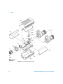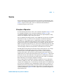
1
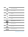
Agilent R8486A and
Q8486A Power Sensor
Operating and Service
Manual
Agilent Technologies
Notices
© Agilent Technologies, Inc. 2006-2008,
2010
No part of this manual may be reproduced in
any form or by any means (including electronic storage and retrieval or translation
into a foreign language) without prior agreement and written consent from Agilent
Technologies, Inc. as governed by United
States and international copyright laws.
Manual Part Number
08486-90026
Edition
Fourth Edition, June 30, 2010
Printed in Malaysia
Agilent Technologies, Inc.
3501 Stevens Creek Blvd.
Santa Clara, CA 95052 USA
Warranty
Safety Notices
The material contained in this document is provided “as is,” and is subject to being changed, without notice,
in future editions. Further, to the maximum extent permitted by applicable
law, Agilent disclaims all warranties,
either express or implied, with regard
to this manual and any information
contained herein, including but not
limited to the implied warranties of
merchantability and fitness for a particular purpose. Agilent shall not be
liable for errors or for incidental or
consequential damages in connection with the furnishing, use, or performance of this document or of any
information contained herein. Should
Agilent and the user have a separate
written agreement with warranty
terms covering the material in this
document that conflict with these
terms, the warranty terms in the separate agreement shall control.
Technology Licenses
The hardware and/or software described in
this document are furnished under a license
and may be used or copied only in accordance with the terms of such license.
Restricted Rights Legend
U.S. Government Restricted Rights. Software and technical data rights granted to
the federal government include only those
rights customarily provided to end user customers. Agilent provides this customary
commercial license in Software and technical data pursuant to FAR 12.211 (Technical
Data) and 12.212 (Computer Software) and,
for the Department of Defense, DFARS
252.227-7015 (Technical Data - Commercial
Items) and DFARS 227.7202-3 (Rights in
Commercial Computer Software or Computer Software Documentation).
ii
CAUTION
A CAUTION notice denotes a hazard. It calls attention to an operating procedure, practice, or the like
that, if not correctly performed or
adhered to, could result in damage
to the product or loss of important
data. Do not proceed beyond a
CAUTION notice until the indicated
conditions are fully understood and
met.
WA R N I N G
A WARNING notice denotes a
hazard. It calls attention to an
operating procedure, practice, or
the like that, if not correctly performed or adhered to, could result
in personal injury or death. Do not
proceed beyond a WARNING
notice until the indicated conditions are fully understood and
met.
R8486A/Q8486A Operating and Service Manual
Certification
Agilent Technologies certifies that this product met its published
specifications at the time of shipment. Agilent further certifies that its
calibration measurements are traceable to the United States National
Institute of Standard and Technology (formerly National Bureau of
Standards), to the extent allowed by that organization’s calibration facility,
and to the calibration facilities of other International Standards
Organization members.
General Warranty
The material contained in this document is provided “as is,” and is subject
to being changed, without notice, in future editions. Further, to the
maximum extent permitted by applicable law, Agilent disclaims all
warranties, either express or implied with regard to this manual and any
information contained herein, including but not limited to the implied
warranties of merchantability and fitness for a particular purpose. Agilent
shall not be liable for errors or for incidental or consequential damages in
connection with the furnishing, use, or performance of this document or
any information contained herein. Should Agilent and the user have a
separate written agreement with warranty terms covering the material in
this document that conflict with these terms, the warranty terms in the
separate agreement shall control. Duration and conditions of warranty for
this product may be superseded when the product is integrated into
(becomes a part of) other Agilent products. During the warranty period,
Agilent will, at its option, either repair or replace products which prove to
be defective. The warranty period begins on the date of delivery or on the
date of installation if installed by Agilent.
Warranty Service
For warranty service or repair, this product must be returned to a service
facility designated by Agilent. For products returned to Agilent for
warranty service, the Buyer shall prepay shipping charges to Agilent and
Agilent shall pay shipping charges to return the product to the Buyer.
However, the Buyer shall pay all shipping charges, duties, and taxes for
products returned to Agilent from another country.
R8486A/Q8486A Operating and Service Manual
iii
Limitation of Warranty
The foregoing warranty shall not apply to defects resulting from improper
or inadequate maintenance by the Buyer, Buyer-supplied products or
interfacing, unauthorized modification or misuse, operation outside of the
environmental specifications for the product, or improper site preparation
or maintenance.
The design and implementation of any circuit on this product is the sole
responsibility of the Buyer. Agilent does not warrant the Buyer’s circuitry
or malfunctions of Agilent products that result from the Buyer’s circuitry.
In addition, Agilent does not warrant any damage that occurs as a result of
the Buyer’s circuit or any defects that result from Buyer-supplied
products.
To the extent allowed by local law, Agilent makes no other warranty,
expressed or implied, whether written or oral with respect to this product
and specifically disclaims any implied warranty or condition of
merchantability, fitness for a particular purpose or satisfactory quality.
Exclusive Remedies
To the extent allowed by local law, the remedies provided herein are the
Buyer’s sole and exclusive remedies. Agilent shall not be liable for any
direct, indirect, special, incidental, or consequential damages (including
lost profit or data), whether based on warranty, contract, tort, or any other
legal theory.
iv
R8486A/Q8486A Operating and Service Manual
Restricted Rights Legend
The Software and Documentation have been developed entirely at private
expense. They are delivered and licensed as “commercial computer
software” as defined in DFARS 252.227-7013 (Oct 1988), DFARS
252.211-7015 (May 1991), or DFARS 252.227-7014 (Jun 1995), as a
“commercial item” as defined in FAR 2.101(a), or as “restricted computer
software” as defined in FAR 52.227-19 (Jun 1987) (or any equivalent
agency regulation or contract clause), whichever is applicable. You have
only those rights provided for such Software and Documentation by the
applicable FAR or DFARS clause or the Agilent standard software
agreement for the product involved.
Technology Licenses
The hardware and/or software described in this document are furnished
under a license and may be used or copied only in accordance with the
terms of such license.
R8486A/Q8486A Operating and Service Manual
v
Safety Summary
The following general safety precautions must be observed during all
phases of operation of this instrument. Failure to comply with these
precautions or with specific warnings elsewhere in this manual violates
safety standards of design, manufacture, and intended use of the
instrument. Agilent Technologies, Inc. assumes no liability for the
customer’s failure to comply with these requirements.
Safety Notices
WA R N I N G
CAUTION
vi
A WARNING notice denotes a hazard. It calls attention to an operating
procedure, practice, or the like that, if not correctly performed or
adhered to, could result in personal injury or loss of life. Do not proceed
beyond a WARNING notice until the indicated conditions are fully
understood and met.
A CAUTION notice denotes a hazard. It calls attention to an operating
procedure, practice, or the like that, if not correctly performed or adhered
to, could result in damage to the product or loss of important data. Do not
proceed beyond a CAUTION notice until the indicated conditions are fully
understood and met.
R8486A/Q8486A Operating and Service Manual
Safety Symbols
The following symbol on the instrument and in the documentation
indicates precautions that must be taken to maintain safe operation of the
instrument.
Caution, risk of danger.
The Instruction Documentation Symbol. The product is marked with this symbol
when it is necessary for the user to refer to the instructions in the supplied
documentation.
Alternating current (AC).
This symbol indicates the operating switch for ‘Stand-by’ mode. Note, the
instrument is NOT isolated from the mains when the switch is pressed.
To isolate the instrument, the mains coupler (mains input cord) should be
removed from the power supply.
Direct current (DC).
Both direct and alternating current.
Three-phase alternating current.
Earth (ground) TERMINAL.
R8486A/Q8486A Operating and Service Manual
vii
PROTECTIVE CONDUCTOR TERMINAL.
Frame or chassis TERMINAL.
Equipotentiality.
On (Supply).
Off (Supply).
Equipment protected throughout by DOUBLE INSULATION or
REINFORCED INSULATION.
Caution, risk of electric shock.
Caution, hot surface.
In position of bi-stable push control.
viii
R8486A/Q8486A Operating and Service Manual
Out position of bi-stable push control.
R8486A/Q8486A Operating and Service Manual
ix
General Safety Information
The following general safety precautions must be observed during all
phases of operation, service, and repair of this instrument. Failure to
comply with these precautions or with specific warnings elsewhere in this
manual violates safety standards of design, manufacture, and intended
use of the instrument. Agilent Technologies assumes no liability for the
customer’s failure to comply with these requirements.
WA R N I N G
CAUTION
x
BEFORE CONNECTING THE POWER SENSOR TO OTHER INSTRUMENTS,
ensure that all instruments are connected to the protective (earth)
ground. Any interruption of the protective earth grounding will cause a
potential shock hazard that could result in personal injury.
• Use the device with the cables provided.
• Repair or service that is not covered in this manual should only be
performed by qualified personnels.
R8486A/Q8486A Operating and Service Manual
In This Guide ...
1
Product Outlook Chapter 1 contains information about initial inspection,
performance tests, adjustments, operation, troubleshooting and repair of
the AG R8486A and AG Q8486A power sensors.
2
Operation Chapter 2 provides the information on the operating
procedures of your AG R8486A and AG Q8486A power sensors.
3
Specifications Chapter 3 describes the specifications for the AG R8486A
and AG Q8486A power sensors.
4
Service Chapter 4 explains the service, performance tests, replaceable
parts and troubleshooting for your AG R8486A and AG Q8486A power
sensors.
R8486A/Q8486A Operating and Service Manual
xi
xii
R8486A/Q8486A Operating and Service Manual
Contents
Contents
1
Product Outlook 1
General Information 2
Description
2
Figure 1-1AG R8486A and AG Q8486A power sensors
Installation 4
Initial Inspection 4
Interconnections
4
Storage and Shipment
3
5
2
Operation 7
Operation
8
Figure 2-2Q–Band Power Sensor to Waveguide
Connection
10
Table 2-1. Cal Factor % to dB Conversion 11
3
Specifications 13
Specifications
14
Table 3-2. Specifications
14
Calibration Factor (CF) and Reflection Coefficient (Rho)
15
Table 3-3. Power Sensor Uncertainty of Calibration Factor
Data
16
4
Service 17
Recommended Test Equipment 18
Table 4-4. Recommended Test Equipment
Performance Tests and Adjustments 19
SWR (Reflection Coefficient) Test 19
Replaceable Parts 23
Table 4-5. Code List of Manufacturers
Table 4-6. Replaceable Parts 24
Figure 4-3Illustrated Parts Breakdown
18
23
28
Service 29
Principles of Operation
29
Figure 4-4Component and Assembly Locations
Agilent U1251A/U1252A User’s and Service Guide
31
xiii
Contents
Figure 4-5Power Sensor Schematic Component and
Assembly Locations
32
Troubleshooting
33
Figure 4-6Operational Amplifier
34
Repair
36
Figure 4-7Removing Power Sensor Shell
38
Figure 4-8Power Sensor Hardware Locations
41
Manual Changes 42
Introduction 42
How to Use Manual Changes
42
Table 4-7. Manual Changes by Serial Prefix or Number
Figure 4-9AG R8486A (2503A) and AG Q8486A (2702A,
2503A) Component Locations
43
42
NOTICE 44
WARRANTY 44
Herstellerbescheinigung
44
Manufacturer’s Declaration
45
xiv
Agilent U1251A/U1252A User’s and Service Guide
Agilent R8486A and Q8486A Power Sensor
Operating and Service Manual
1
Product Outlook
General Information
Installation 4
2
Agilent Technologies
1
1
Introduction
General Information
This Operating and Service Manual contains information about initial
inspection, performance tests, adjustments, operation, troubleshooting and
repair of the AG R8486A and AG Q8486A power sensors.
Description
The AG R8486A and AG Q8486A are thermocouple power sensors. They
measure power levels in a range from –30 dBm to +20 dBm (1 μW to 100 mW).
The AG R8486A measures at frequencies from 26.5 GHz to 40 GHz. The AG
Q8486A measures at frequencies from 33 GHz to 50 GHz.
2
R8486A/Q8486A Operating and Service Manual
Introduction
1
Figure 1-1 AG R8486A and AG Q8486A power sensors
R8486A/Q8486A Operating and Service Manual
3
1
Introduction
Installation
Initial Inspection
Inspect the shipping container for damage. If the shipping container or
packaging material is damaged, it should be kept until the contents of the
shipment have been checked mechanically and electrically. If there is
mechanical damage or if the instrument does not pass the performance test,
notify the nearest Agilent Technologies office. Keep the damaged shipping
materials (if any) for inspection by the carrier and an Agilent Technologies
representative.
Interconnections
The AG R8486A and AG Q8486A power sensors have two inputs: a Type–N
connector for a 50 MHz 1 mW calibration signal generated by the power meter,
and a waveguide flange to connect to the device under test.
Refer to the power meter operating and service manual for interconnecting
instructions.
CAUTION
4
Connect the power sensors by turning only the nut on the Type–N connector. Damage
can occur if torque is applied to the power sensors body.
R8486A/Q8486A Operating and Service Manual
Introduction
1
Storage and Shipment
Environment
The instruments should be stored in a clean, dry environment. The following
limitations apply to both storage and shipment:
Temperature
–55 to + 75 °C
Relative Humidity
less than 95% at 40 °C
Altitude
less than 15,300 meters (50,000 feet)
Original Packaging
Containers and materials identical to those used in factory packaging are
available through Agilent Technologies offices. If the instrument is being
returned to Agilent Technologies for servicing, attach a tag indicating the type
of service required, return address, model number, and serial number. Also,
mark the container FRAGILE to assure careful handling. In any
correspondence, refer to the instrument by model number and serial number.
R8486A/Q8486A Operating and Service Manual
5
1
6
Introduction
R8486A/Q8486A Operating and Service Manual
Agilent R8486A and Q8486A Power Sensor
Operating and Service Manual
2
Operation
Operation
8
Agilent Technologies
7
2
General Power Meter Functions
Operation
WA R N I N G
BEFORE CONNECTING THE POWER SENSOR TO OTHER INSTRUMENTS ensure that
all instruments are connected to the protective (earth) ground. Any interruption of
the protective earth grounding will cause a potential shock hazard that could result
in personal injury.
Operating Environment
The operation environment for the power sensors should be within the
following limits:
8
Temperature:
0 to +55 °C
Relative Humidity:
less than 95% at 40 °C
Altitude:
less than 4550 meters (15,000 feet)
R8486A/Q8486A Operating and Service Manual
General Power Meter Functions
2
Operating Precautions
CAUTION
If the following energy and power levels are exceeded, the power meter system may
be damaged.
• Maximum Average Power: 300 mW
• Maximum Peak Power: 15 W
• Maximum Energy Per Pulse: 30 W.µs
Use the plastic flange cover to protect the waveguide connector from dirt and
mechanical damage whenever it is not in use. Any burrs, dents or dirt on the flange or
waveguide surface will increase the SWR.
The Type–N connector plastic bead deteriorates when contacted by any chlorinated or
aromatic hydrocarbons such as acetone, trichlor, carbon tetrachloride, benzene, etc.
Clean the connector face with a cotton swab saturated in isopropyl alcohol.
For Q8486A only, damage may occur to the precision waveguide flange if the following
procedure is not followed:
1 Torque the waveguide flange screws to no more than 60 inch-ounces (0.42 N.m)
maximum.
2 Insert the two screws, indicated in Table 2-1, from the power sensor side of the
flange. The other two screws can be inserted from either side of the flange. Tighten
the four screws until just finger tight.
3 Using a calibrated torque wrench, tighten the flange by going back and forth
between screws that are opposite each other, tightening each screw by small
increments until reaching the desired torque. If using the hex ball driver, hold
between thumb and forefinger to avoid excess torque. Do not fully torque one
screw before tightening the other. Using extreme care not to over–torque when
using the hex ball driver.
R8486A/Q8486A Operating and Service Manual
9
2
General Power Meter Functions
Insert this screw,
and the one
opposite (hidden
under instrument),
as shown.
Figure 2-2 Q–Band Power Sensor to Waveguide Connection
Power Meter Calibrations
AG R8486A and Q8486A power sensors have a reference calibration factor of
100%. Calibrate your power meter and power sensor according to directions
given in the power meter manual.
Power Measurements
To correct for varying thermocouple responses at different frequencies a cal
factor chart is included on the power sensors. To use the cal factor at the
frequency of interest, adjust the power meter's CAL FACTOR control according
to the instructions in the power meter's operating and service manual. Note
that in some cases, there may be a cal factor value of less than 85% listed in the
sensor. When using the sensor with the AG 438A power meter, merely enter
the cal factor value. If an AG 435B or 436A power meter is being used, set the
cal factor control to 100%, and divide the reading in watts units (milliwatts or
microwatts) by the decimal equivalent of the cal factor. For example, if the cal
factor is 75%, divide the reading by 0.75. (This will result in a larger value of
power than that displayed by the meter.)
10
R8486A/Q8486A Operating and Service Manual
General Power Meter Functions
2
If reading in dBm, use the chart in Table 2- 1 to convert the cal factor to dB
and add this value to the reading. Interpolate for values between those shown.
As above, the cal factor control should be set to 100%. For example, if the cal
factor is 75%, add 1.25 dB to the displayed value.
The above procedure has eliminated some mathematical steps, the following
formula may be of some use:
Correction dB = Reading dB – 10 log10 Cal Factor (decimal).
Table 2-1 Cal Factor % to dB Conversion
Cal Factor
dB
Cal Factor
dB
Cal Factor
dB
50%
3.01
62%
2.08
74%
1.31
51%
2.92
63%
2.01
75%
1.25
52%
2.84
64%
1.94
76%
1.19
53%
2.76
65%
1.87
77%
1.14
54%
2.68
66%
1.80
78%
1.08
55%
2.60
67%
1.74
79%
1.02
56%
2.52
68%
1.67
80%
0.97
57%
2.44
69%
1.61
81%
0.92
58%
2.37
70%
1.55
82%
0.86
59%
2.29
71%
1.49
83%
0.81
60%
2.22
72%
1.43
84%
0.76
61%
2.15
73%
1.37
85%
0.71
Operating Instructions
To operate the Power Sensor, refer to the operating instructions in Section III
of the power meter operating and service manual. Note, under power meter
calibrations above, that each power meter requires a different calibration
procedure.
R8486A/Q8486A Operating and Service Manual
11
2
General Power Meter Functions
Modulation Effects
When measuring microwave sources that are modulated at the chopper
frequency (nominally 220 Hz), or at the first or second harmonic or
submultiples of the chopper frequency, beat notes will occur. Unless these beat
notes are exactly the chopper frequency, they can usually be eliminated by
averaging since the amplitudes are plus and minus the actual power. These
frequencies may also be avoided by changing the modulation frequency
slightly, if possible.
If an AG 438A is being used, select a manual filter setting of greater than 3 to
minimize beat note interference.
12
R8486A/Q8486A Operating and Service Manual
Agilent R8486A and Q8486A Power Sensor
Operating and Service Manual
3
Specifications
Specifications
14
Agilent Technologies
13
3
Using P-Series Power Sensor
Specifications
(Specifications for the power sensors are in Table 3-2) The power sensors
contain two thermocouples (with two thin- film resistors) on a silicon chip.
The thermal/mechanical layout of the thermocouple is selected to give a hot
junction at the resistor (center of the chip) and a cold junction at the outer
edge of the chip.
Table 3-2 Specifications
Frequency Range:
AG R8486A: 26.5 GHz to 40 GHz
AG Q8486A: 33 GHz to 50 GHz
Power Range:
–30 dBm to +20 dBm
(1 µW to 100 mW)
Nominal Impedance:
50 Ω
Maximum SWR
AG R8486A: 1.4 (0.167)
(Reflection Coefficient):
AG Q8486A: 1.5 (0.200)
50 MHz Calibration Port SWR1:
< 1.15 (0.070)
Waveguide Flange:
AG R8486A: UG-599/U2
AG Q8486A: UG-383/U
Maximum Power:
300 mW Average3
Maximum Peak Power:
15 W
Maximum Energy/Pulse
30 W.µs
Operating Temperature:
0 to +55 ºC
Worst case Power Linearity4:
+2% to –4% 10 mW to 100 mW
1 Coaxial connector for 50 Mhz calibration is Type–N male.
2 Rectangular cover flange for circular cover flange, use AG 11516A Adapter.
3 For pulses greater than 30 W the maximum average power (P) is limited by the energy per pulse
(E) in W.ms according to P = 30 – 0.02E
4 Negligible deviation except for those power ranges noted.
14
R8486A/Q8486A Operating and Service Manual
Using P-Series Power Sensor
3
When the resistor at the hot junction converts the applied microwave energy
to heat, the temperature difference between the hot and cold junctions
generates a dc voltage (thermoelectric emf). The dc voltage is proportional to
the temperature difference between the junctions and, therefore, proportional
to the power from the microwave source. The dc voltage thus generated is a
very low–level voltage (approximately 160 nV for 1 μW applied power) and
requires amplification before it can be transferred on standard cables.
The amplification is provided by an input amplifier assembly which consists a
chopper (sampling gate) and an input amplifier. The dc voltage is routed on
gold wires to the chopper circuit which converts the low–level dc voltage to an
ac voltage. To do this, the chopper uses two field effect transistors (FETs)
controlled by a 220 Hz square wave generated by the power meter. The result
is an ac output signal proportional to the dc input. The ac signal is then
amplified by the input amplifier. The relatively high–level ac signal output can
now be routed by standard cables.
In application, the power sensors are connected between a microwave source
and a compatible power meter. (Suitable meters are the AG 435B, AG 436A, AG
437B and AG 438A.) The power sensors provide a matched load for the
microwave source. This load is determined by the thermocouples which are
each 100 ohms and are in parallel to the internal microwave coaxial lines. The
very low SWR to 40 or 50 GHz is possible because of the low parasitics of the
thermocouple chip and the multi–stepped coax–to–waveguide transition
(which adapts the 50 ohm thermocouple impedance to the desired waveguide
impedance). The power meter indicates the power dissipated in these
thermocouples in μW (or mW) or in dBm.
Calibration Factor (CF) and Reflection Coefficient (Rho)
CAL FACTOR and reflection coefficient data are provided on a label attached
to the cover. Maximum uncertainties of the CAL FACTOR data are listed in
Table 3- 2. The CAL FACTOR compensates for the frequency response of the
sensors.
R8486A/Q8486A Operating and Service Manual
15
3
Using P-Series Power Sensor
Table 3-3 Power Sensor Uncertainty of Calibration Factor Data
Uncertainty of AG R8486A Calibration Factor at 1 mW
Uncertainty of AG Q8486A Calibration Factor at 1 mW
Frequency (Ghz)
Worse Case
Uncertainty (%)
Probable
Uncertainty (%)
Frequency (Ghz)
Worse Case
Uncertainty (%)
Probable
Uncertainty (%)
26.5
6.10
3.08
33
7.85
4.03
27
6.72
3.15
34.5
7.84
4.03
28
6.76
3.19
35
8.39
4.06
29
6.20
3.17
36
7.69
3.99
30
6.75
3.18
37
7.70
3.99
31
6.10
3.08
38
8.34
4.05
32
6.67
3.13
39
8.37
4.06
33
6.05
3.06
40
7.80
4.02
34
6.64
3.12
41
9.33
4.42
34.5
6.04
3.06
42
10.25
4.78
35
6.59
3.10
43
10.98
5.11
36
5.89
3.02
44
11.10
5.41
37
5.90
3.02
45
12.27
5.71
38
6.53
3.09
46
12.84
5.97
39
6.56
3.1
47
12.50
6.17
40
6.00
3.06
48
12.8
6.03
49
12.30
5.84
50
11.00
5.59
Reflection Coefficient (Rho — or ρ) relates to SWR according to the following
formula:
SWR = (1 + ρ/1 – ρ)
16
R8486A/Q8486A Operating and Service Manual
Agilent R8486A and Q8486A Power Sensor
Operating and Service Manual
4
Service
Recommended Test Equipment 18
Performance Tests and Adjustments
19
Agilent Technologies
17
4
CCDF
Recommended Test Equipment
Table 4-4 lists the test equipment recommended to check, adjust, and
troubleshoot the power sensors. If substitute equipment is used, it must meet
or exceed the critical specifications.
Table 4-4 Recommended Test Equipment1
Instrument
Digital Voltmeter
Critical Specifications
Recommended Model
Use*2
Range 100 mW Vdc
AG 3478A
T
AG 54200A
A, T
AG 10004D
A
AG 3478A
A, T
Input impedance: 10 megohms
Resolution: 4–digit
Accuracy: ±0.05% ± 1 digit
Oscilloscope
Bandwidth: dc to 50 MHz
Sensitivity: Vertical, 0.2 V/div
Sensitivity: Horizontal, 1 ms/div
10 : 1 Divider Probe
10 megohms
10 pF
Multimeter
Range: 1 ohm to 100, 000 ohms
20 mV, full scale
Accuracy: ±5%
DC Power Supply
Range: 0 to 20 Vdc
AG 6200B
T
Power Meter
Availability of test point after 3rd amplifier
and prior to phase detector.
AG 435B
A
1 Equipment for an SWR test is not listed here because there are several different techniques for measuring SWR. However,
some suggestions for test equipment are made in the instructions for the SWR test.
2 A = Adjustments T= Troubleshooting
18
R8486A/Q8486A Operating and Service Manual
CCDF
4
Performance Tests and Adjustments
SWR (Reflection Coefficient) Test
This section does not establish preset SWR test procedures since there are
several test methods and different equipment available for testing the SWR or
reflection coefficient. Therefore, the actual accuracy of the test equipment
must be taken into account when measuring against instruments
specifications to determine a pass or fail condition.
To measure the SWR across the waveguide band, use a directional coupler and
detector selected for the band of interest. The directional coupler should have
a directivity greater than 37dB. The detector should have greater than 0.3
mV/mW sensitivity and should be calibrated with a rotary vane attenuator
with an accuracy of 2%. A convenient source is a frequency tripler driven by
an AG 8350B and an AG 83594A. An AG 8349A can also be used as a source if
the tripler can handle 100 mW of input power.
CAUTION
Some frequency triplers are very delicate and are close to burn out at 100 mW. We
suggest 3 dB of attenuation to start, and a high pass filter, (such as a pair of AG P281C
adaptors back to back) because the AG 83594A can be capable of greater than 150
mW at low frequencies and will damage the tripler.
To check the calibration factor, the power sensors should be compared with
another recently calibrated power sensor. The source should be leveled with a
reference coupler that has low SWR and high directivity to monitor or level the
incident power.
For reflection measurements we suggest Agilent Application Note 183 ''High
Frequency Swept Measurements''. For calibration factor and error analysis we
suggest Agilent Application Note 64–1 ''Fundamentals of RF and Microwave
Power Measurements''.
R8486A/Q8486A Operating and Service Manual
19
4
CCDF
NOTE
While the flange of the AG R8486A is similar to the one described in MIL
F–3922/54C–003, the AG Q8486A has been modified to mate with greater precision to
MIL–3922/67B–006 flanges. The true position of the holes relative to each other are held
to a diameter tolerance of 0.0254 mm (0.001''). The holes are held to 1.664 mm (0.0655'')
minimum diameter while the pins are held to 1.61 mm (0.0634'') maximum diameter.
FET Balance Adjustment
WA R N I N G
The following procedure exposes high voltage areas within the power meter. Use
extreme care while working around these areas or personal injury could occur.
Equipment
Oscilloscope:
AG 54200A
Power Meter:
AG 435B
Multimeter:
AG 3478A
The sampling gate balance is affected by the relative positions of the wires in
the power sensors, which connect to pins G and H of connector J1. One wire is
black and white; the other is brown and white. Moving the black and white
wire will adjust the switching transient amplitude (spike). Moving the brown
and white wire will change the offset. Once positioned, be careful not to
displace these wires. To correctly position these wires, after replacement of
A2U1, or if the wires have been moved so as to affect the sampling gate
balance, perform the following procedure.
NOTE
20
If the power sensor printed circuit board A2 has been removed for repair, make sure all
surfaces are thoroughly clean and free of flux residues before attempting the following
adjustments.
R8486A/Q8486A Operating and Service Manual
CCDF
4
1 Set the multimeter controls as follows:
FUNCTION:
Voltage
Range:
20 mV, full scale
2 Set oscilloscope controls as follows:
SENSITIVITY:
0.2V/DIV
SWEEP:
1 ms/DIV
TRIGGER:
INT+
Display:
A
3 Set the power meter CAL FACTOR to 100%. Set the power meter RANGE to
1 mW (0 dBm).
4 Open the power sensor (see Disassembly Procedure, Steps 1 through 3).
Zero and calibrate the power meter. Leave the opened power sensor
connected to the power meter POWER REF output. Heat can affect the
adjustments so handle the sensor as little as possible.
5 Turn OFF the POWER REF switch on the rear panel of the power meter.
6 Remove the AG 435B bottom panel. This will expose the circuit side of the
A5 printed circuit board. On A5 you will see a long double row of soldered
terminals numbered 1 to 44.
7 Connect a probe from pin 40 (the number 902 is printed on the board next
to pin 40) to the multimeter input.
8 Lay the AG 435B on its left side and remove the right panel. This will expose
the A4 assembly.
9 Connect a 1:1 probe from TP4 to channel A on the oscilloscope.
10 Offset. Read the multimeter and adjust the position of the brown and white
wire until the reading is between –7.0 mV and –2.0 mV. Helpful hint: the
relative position of the brown and white wire to C4 will adjust the offset.
11 Switching transients. Read the oscilloscope and adjust the position of the
black and white wire until the switching transients are less than 0.8V peak
R8486A/Q8486A Operating and Service Manual
21
4
CCDF
to peak. Helpful hint: the relative position of the black and white wire to the
collector of Q1 will adjust the switching transients.
12 You will find that positioning the wire for switching transients affects the
offset. Go back and forth between the two wires, positioning and
repositioning, until both adjustments are within specifications.
22
R8486A/Q8486A Operating and Service Manual
CCDF
4
Replaceable Parts
Table 4-6 is a list of replaceable parts. Figure 4-3 is the illustrated parts
breakdown (IPB) that identifies the major assemblies and chassis parts. The
mounting locations of the components on the A2 Input Amplifier Assembly are
shown in Figure 4-4. To order a part, quote the Agilent part no and Check Digit
(CD), specify the quantity required, and address the order to the nearest
Agilent Technologies office (see NOTE below). To order a part not listed in
Table 4-5, give the instrument model number, instrument serial number, the
description and function of the part, and the quantity of parts required.
NOTE
Within the USA, it is better to order directly from the Agilent Parts Center in Mt. View,
California. Ask your nearest Agilent Technologies office for information and forms for the
''Direct Mail Order System''
Table 4-5 Code List of Manufacturers
Mfr Code
Manufacturer Name
Address
Zip Code
00000
ANY SATISFACTORY SUPPLIER
00843
HOFFMAN ENG CO DIV OF FED CARTRIDGE
ANOKA MN
55303
01640
MULTIMATIC PRODUCTS INC
HAUPPAUGE NY US
11788
01686
RCL ELECTRONICS INC
NORTHBROOK IL US
60062
01766
INTL CRYSTAL MFG CO INC
OKLAHOMA CITY OK
73102
05876
U S POLYMERIC INC
STAMFORD CT
06904
06383
PANDUIT CORP
TINLEY PARK IL US
60477
09969
DALE ELECTRONICS INC
YANKTON SD US
57078
11045
AM CASTLE & CO INC
FRANKLIN PARK IL US
60131
11502
IRC INC
BOONE NC US
28607
12344
TALLY CORP
KENT WA
98031
12498
CRYSTALONICS DIV TELEDYNE
CAMBRIDGE MA
02140
24931
SPECIALTY CONNECTOR CO
FRANKLIN IN US
46131
R8486A/Q8486A Operating and Service Manual
23
4
CCDF
Table 4-5 Code List of Manufacturers (continued)
Mfr Code
Manufacturer Name
Address
Zip Code
28480
AGILENT TECHNOLOGIES CO CORPORATE HQ
PALO ALTO
94304
84830
LEE SPRING CO
BROOKLYN NY US
11219
Table 4-6 Replaceable Parts
Reference
Designation
Agilent Part
Number
CD
Qty
Description
Mfr Code
Manufacturer Part
Number
A1
08486–60001
5
1
BULKHEAD AY R
28480
08486–60001
A1
08486–60002
6
1
BULKHEAD AY Q
28480
08486–60002
A2
08481–60025
8
1
POWER SENSOR BOARD
ASSEMBLY
28480
08481–60025
A2C1
0180–2515
8
2
CAPACITORêFXD 47F ± 20% 6 VDC
TA
12344
T355F476M006AS
A2C2
0160–4306
7
4
CAPACITOR–FXD 100PF ± 10% 100
VDC CER
00843
0805C101K3P
A2C3
0160–4306
7
–
CAPACITOR–FXD 100PF ± 10% 6
VDC TA
00843
0805C101K3P
A2C4
0180–0594
9
1
CAPACITOR–FXD 3.3UF ± 20% 15
VDC TA
12344
T350A335M016AS
A2C5
0160–3094
8
1
CAPACITOR–FXD .1UF ± 10% 100
VDC CER
06383
FD22X5R2A104K
A2C6
0160–3879
7
1
CAPACITOR–FXD .01UF ± 20% 100
VDC CER
09969
RPE121–105X7R10
3M100V
A2C7
0160–4306
7
–
CAPACITOR–FXD 100PF ± 10% 100
VDC CER
00843
0805C101K3P
A2C8
0160–4306
7
–
CAPACITOR–FXD 100PF ± 10% 100
VDC CER
00843
0805C101K3P
AC29
0180–2515
8
CAPACITOR–FXD 47UF ± 20% 6
VDC TA
12344
T355F476M0Q6AS
24
R8486A/Q8486A Operating and Service Manual
CCDF
4
Table 4-6 Replaceable Parts (continued)
Reference
Designation
Agilent Part
Number
CD
Qty
Description
Mfr Code
Manufacturer Part
Number
A2C10
0180–2545
4
1
CAPACITOR–FXD 100UF ± 20% 4
VDC TA
01766
202l6301–107–M6–5 52
A2Q1
1854–0610
0
1
TRANSISTOR NPN SI TO–46 FT =
800 MHZ
28480
1854–0610
A2R1
0698–3260
9
1
RESISTOR 464K ± 1% .125W TF TC
= 0 ± 100
12498
CT4
A2R2
0698–7428
1
1
RESISTOR 3.16K ± 1% .05W TF TC
= 0 ± 100
12498
C3–1/8–TO–3161–F
A2R3
0698–7224
3
1
RESISTOR 1K ± 1% .05W TF TC = 0
± 100
12498
C3–1/8–TO–316R–F
A2R4
0698–7236
7
1
RESISTOR 316 ± 1% .05W TF TC =
0 ± 100
12498
C3–1/8–TO–1001–F
A2R5
0811–3210
1
1
RESISTOR 31.6 ± 5% .05W PN TC
= 5040 ± 250
01686
R342
A2U1
1813–0060
8
1
IC MISC TO–8 PKG
28480
1813–0060
ACCESSORIES
1390–0671
9
1
Q FLANGE SCREW 4–40 THD;
.312IN
28480
1390–0671
1401–0211
8
1
Q FLANGE COVER
11502
030–302 (WR 22)
2260–0002
6
6
R FLANGE NUT 4–40–THD
.062–IN–THK
00000
ORDER BY
DESCRIPTION
3030–0209
9
6
R FLANGE SCREW 4–40 .5–IN–LG
ALY STL
00000
ORDER BY
DESCRIPTION
5040–0359
3
1
R FLANGE COVER
28480
5040–0359
8710–1539
7
1
BALLDRIVER–HEX
11045
#A25
CHASSIS PARTS]
J1
08481–60024
7
1
CONNECTOR ASSEMBLY–12 PIN
28480
08481–60024
MP1
08481–40002
9
2
SHELL–PLASTIC
28480
08481–40002
R8486A/Q8486A Operating and Service Manual
25
4
CCDF
Table 4-6 Replaceable Parts (continued)
Reference
Designation
Agilent Part
Number
CD
Qty
Description
Mfr Code
Manufacturer Part
Number
MP2
08481–40002
9
–
SHELL PLASTIC
28480
08481–40002
MP3
08481–20011
8
2
CHASSIS
28480
08481–20011
MP4
08481–20011
8
–
CHASSIS
28480
08481–20011
MP5
08481–20008
3
1
END BELL
28480
08481–20008
MP6
1460–4306
9
1
SPRING–CPRSN .88–IN–OA–LG
84830
C1–0088–2–SS
MP7
1251–3363
8
1
NUT–AUDIO CONN
05876
91–T–1335–6–9
MP8
08481–00002
5
2
SHIELD
28480
08481–00002
MP9
08481–00002
5
–
SHIELD
28480
08481–00002
MP10–MP18
3030–0954
1
9
SCREW–SKT HD CAP 0–80
.188–IN–LG SST–304
00000
ORDER BY
DESCRIPTION
MP19–MP22
3030–0422
8
4
SCREW–SKT HD CAP 0–80
.188–IN–LG SST–302
00000
ORDER BY
DESCRIPTION
MP23
3030–0436
4
1
SCREW–SKT HD CAP 0–80
.5–IN–LG SST–300
00000
ORDER BY
DESCRIPTION
MP24
5040–6939
7
1
CLAMP
28480
5040–6939
MP25
5040–6940
0
1
BLOCK
01640
5040–6940
MP26
08486–80003
9
1
LABEL–MODEL Q
28480
08486–80003
MP26
08486–80004
0
1
LABEL–MODEL R
28480
08486–80004
MP27
08486–80005
1
1
LABEL INFO (SIDE)
28480
08486–80005
MP28
1250–0016
0
1
COMPONENT–RF CONNECTORE
SERIES N; .75 IN
24931
R100–1
MP29
1250–0916
9
1
BODY–RF CONNECTOR Series
APC–N; STRAIGHT
01640
1250–0916
MP30
1250–0918
1
1
COMPONENT–RF CONNECTOR
SERIES APC–N; SST
01640
1250–9016
MP31
08486–80006
2
1
CAL–LABEL (BLANK)
26
R8486A/Q8486A Operating and Service Manual
CCDF
4
Table 4-6 Replaceable Parts (continued)
Reference
Designation
Agilent Part
Number
CD
Qty
Description
MP32
08481–80005
6
1
MYLAR TAPE (COVERS CAL
LABEL)
MP33
7120–2422
7
1
LABEL WARNING (SIDE)
R8486A/Q8486A Operating and Service Manual
Mfr Code
Manufacturer Part
Number
27
4
CCDF
Figure 4-3 Illustrated Parts Breakdown
28
R8486A/Q8486A Operating and Service Manual
CCDF
4
Service
Service instructions consist of principles of operation, troubleshooting, and
repairs. Test equipment which meets or exceeds the critical specifications in
Table 4-4 may be used in place of the recommended instruments for
troubleshooting the power sensor.
Principles of Operation
For the following discussion, refer to the schematic diagram in Figure 4-5 and
the simplified diagram of the operational amplifier in Figure 4-6. The
operational amplifier is made up of the power sensor input amplifier, A2Q1,
and the first amplifier stage in the power meter.
The A1 Bulkhead Assembly provides a low SWR load into both the waveguide
input and the Type–N connector. The waveguide is terminated through a
waveguide–to–coax adapter into a coaxial thermocouple. The adapter is
shorted at the calibration input through a choke assembly to block microwave
frequencies fed into the waveguide. However, the adaptor will still allow 50
MHz to be applied through the type- N connector for calibration purposes. This
allows the power sensors to be conveniently adjusted for sensitivity changes
caused by aging, variations in temperature, and inadvertent overloads.
The RF signal is absorbed by the thermocouples which generate a dc voltage
proportional to the RF input power. The dc voltage is routed from the
thermocouples to the input amplifier on gold wires to reduce undesired
thermocouple effects. The gold wires pass through ferrite beads A2E1 and
A2E2 which are located in the black plastic book. (See Figure 4-5.) The ferrite
beads increase the self–inductance of the gold wires causing this portion of
the wires to provide the properties of an RF choke. The result is to minimize
RF feedthrough to the A2 Input Amplifier Assembly.
The dc output from the bulkhead assembly is applied to the two field effect
transistors (FETs) in A2U1. These transistors function as a sampling gate or
chopper. The sampling rate is controlled by a 220 Hz square wave supplied by
the power. The amplitude of the sampling gate output (at pin 3 of A2U1) is a
220 Hz square wave proportional to the power input. The sampled 220 Hz ac
output is applied to the input amplifier A2Q1 which is the input stage for an
operational amplifier (Figure 4-5). The ac gain of the operational amplifier is
approximately 700.
R8486A/Q8486A Operating and Service Manual
29
4
CCDF
A dc feedback voltage from the power meter Auto Zero circuit is coupled to the
input od FET A2U1Q1 to set the zero level. The voltage is developed across the
voltage divider consisting of A2R1 and the series resistance of the
thermocouple A1TC1.When the power sensor is used with the AG 436A or AG
438A Power Meter, the short to ground at J1–K (Mount Resistor) causes the
power meter to automatically select the proper measurement range of –30 to
+20 dBm.
30
R8486A/Q8486A Operating and Service Manual
CCDF
4
Figure 4-4 Component and Assembly Locations
R8486A/Q8486A Operating and Service Manual
31
4
CCDF
Figure 4-5 Power Sensor Schematic Component and Assembly Locations
32
R8486A/Q8486A Operating and Service Manual
CCDF
4
Troubleshooting
The troubleshooting information is intended to isolate a problem to a stage.
The defective component can then be identified by voltage and resistance
checks. The FETs in A2U1 are light sensitive and dc levels are shifted slightly
when the FETs are exposed.
CAUTION
Excessive power will damage the thermocouples and cause their resistance to
increase.
When the microwave input power is 100mW, the bulkhead assembly generates
+12 ± 3 mV. This voltage is measured at A2U1 pin 1. The voltage changes if the
input amplifier is inoperative, or if the bulkhead assembly is disconnected
from the input amplifier.
Resistance measured across the two gold wires from the A1 assembly should
be 200 ± 10 ohms.
CAUTION
Be extremely careful when measuring across the gold wires. They are delicate and
can be damaged easily.
R8486A/Q8486A Operating and Service Manual
33
4
CCDF
Figure 4-6 Operational Amplifier
NOTE
34
If the A1 Bulkhead Assembly is defective, the entire assembly must be replaced.
R8486A/Q8486A Operating and Service Manual
CCDF
4
FET Testing
Check FETs in A2U1 using the following procedure:
a Disconnect cables from power sensor.
b Remove upper chassis from power sensor. (Refer to “Disassembly
Procedure”).
c Measure resistance between pins 1 and 2 of A2U1. Resistance should be
15 ± 0.75 ohms. Measure the same resistance between pins 8 and 9 of
A2U1.
d Short pins 4, 6, and 9 of A2U1 together. Measure resistance between pins
2 and 3, and between pins 3 and 8 of A2U1. Resistance should be less
than 40 ohms.
e Remove short.
f Set a power supply to 10 Vdc.
g Connect positive side of power supply to power sensor signal ground.
Connect negative power supply lead to pins 4 and 6 of A2U1.
h Measure resistance between pins 2 and 3 of A2U1 and between pins 3
and 8. In both cases, resistance should be several hundred times
resistance measured in step d. Testing 220 Hz Drive. To ensure the 220
Hz drive is correct, check the following levels of the square wave with an
oscilloscope:
• –0.05 ± 0.05 Vdc (top of square wave).
• > –9 Vdc (bottom of square wave).
In most cases, the operational amplifier (made up of A2U1 and the first
amplifier in the power meter, (Figure 4-6) is operating correctly if the dc
voltage on the metal cover of A2Q1 (collector) is –70 ± 30 mV dc.
R8486A/Q8486A Operating and Service Manual
35
4
CCDF
Repair
CAUTION
Do not handle the A2 input amplifier circuit board more than necessary. It is
particularly important to keep the area around A2U1 clean. Dirt or moisture from the
hands may make circuits inoperative.
After using solder–flux remover on the A2 input amplifier circuit board, clean the
circuit board with a freon–ethylene alcohol solvent such as MS 175 manufactured by
Miller Stephenson Chemical Co. This removes the flux residue that could make
circuits inoperative in humid conditions.
Soldering Procedures
The power sensor is a high sensitivity device, and is affected by very small
differences in temperature between its components. Therefore, after doing any
soldering in the unit, wait several hours for the unit to reach thermal
equilibrium before using or testing it.
Capacitors A2C2, A2C3, A2C7, and A2C8 (Figure 4-3) require
low–temperature soldering techniques. The connection to these capacitors is a
gold film deposited on a ceramic base. Molten solder causes the gold to form
an amalgam with the solder so the gold dislodges from its ceramic base.
Soldering must be done quickly using a low–temperature soldering iron and
solder. The capacitors must be discarded if unsoldered. If integrated circuit
A2U1 or transistor A2Q1 is replaced, two of these capacitors must be removed,
and therefore must be replaced with new ones. The required low–temperature
soldering iron and solder are as follows:
a Hexagon Thermo–O–Trac soldering iron with J206X tip, temperature
5001/8F (3111/8C)
b Low–temperature solder SN 62, Agilent part number 5090–0410.
Connector Cleaning
Use the following procedure for cleaning the RF connector face.
CAUTION
36
The RF connector bead in the Type–N connector deteriorates when contacted by an
chlorinated or aromatic hydrocarbon such as acetone, trichlor, carbon tetrachloride,
benzene, etc.
R8486A/Q8486A Operating and Service Manual
CCDF
4
To clean the connector face, use a cotton swab saturated in isopropyl alcohol.
Disassembly Procedure
Disassemble the power sensor by performing the following steps:
CAUTION
Disassembly must be performed in sequence described below, otherwise damage may
be caused to the two gold wires between the bulkhead assembly and the input
amplifier assembly. If these wires are damaged, the A1 Bulkhead Assembly must be
returned to the factory for repair
a At rear of power sensor, insert blade of small screwdriver between the
plastic shells (Figure 4- 4).
b Pry alternately at both sides of connector J1 until plastic shells are
apart. Remove shells and magnetic shields.
c Positioned power sensor as shown in Figure 4- 5, top view. (Small hole
[5] should be on left side of RF input connector). Remove allen cap
screws (1), (2), (10), and (13). Loosen screws (11), and (12). Remove
upper chassis from power sensor.
NOTE
In order to loosen the allen cap screws that secure the chassis, a 3/32 allen ball driver is
recommended.
d Remove clamp screw (7) together with the screw spring and clamp (16).
This will free two gold wires that come from bulkhead assembly.
e Remove cap screws (6), (3), and (4).
f Slide bulkhead assembly straight out from chassis.
g If A2 Input Amplifier Assembly must be removed, then remove cap
screws (8), (9), (11), (12), (14), and (15).
h Lift input amplifier and J1 connector out of chassis.
NOTE
Every power sensor has an individually prepared table on the housing. If more than one
power sensor is disassembled at a time, be sure to mate the correct power sensor and
housing when reassembling.
R8486A/Q8486A Operating and Service Manual
37
4
CCDF
Figure 4-7 Removing Power Sensor Shell
Reassembly Procedure
Use the following procedure to assemble the power sensor.
CAUTION
38
The two gold wires connecting the A1 Bulkhead Assembly and the A2 Input Amplifier
Assembly are extremely delicate and may be easily broken. Be careful when working
around them.
R8486A/Q8486A Operating and Service Manual
CCDF
4
a Set printed circuit board and connector into place as shown in
Figure 4-8, opened view.
b Insert cap screws (8), (9), (11), (12), (14), and (15) but do not tighten.
c Center A2 circuit board so there is equal air gap between each side and
chassis. Tighten cap screws (8), (9), (14), and (15).
d Remove black plastic block (17) from printed circuit board. Position
bulkhead assembly with small hole (5) on your left; position block (17)
with flat side towards bulkhead assembly (grooved side out), and guide
pins down. Insert gold wires through holes in block (17) (MP25,
Figure 4-5).
e Set bulkhead assembly straight down on chassis. Mate two guide pins on
block (17) with two holes in printed circuit board (Figure 4-5).
NOTE
Gold wires will lay on or near electrical gold pads at input at FET A2U1.
f Insert screws (3) and (4) and tighten.
g Using tweezers, position (adjust) gold wires over electrical pads. Wires
pass directly over pads. Wires pass directly over pads.
h Place and hold plastic clamp (16) over gold wires. (Ensure that wires
have not moved from position set in step g.) Tighten clamp screw (7) only
enough to hold wires firmly in place.
CAUTION
NOTE
DO NOT tighten clamp screw (7) completely or FET circuit may be broken.
The following procedure will ensure that the gold wires are clamped to the pads correctly.
1 Connect power sensor to power meter and a known power source.
2 Tighten screw (7) to point where power meter indicates normal reading, yet
short of completely collapsing the spring.
R8486A/Q8486A Operating and Service Manual
39
4
CCDF
3 If a normal reading is unobtainable, repeat steps g and h above and this
procedure.
4 Loosen screws (3) and (4). Insert screw (6) and tighten.
5 Place upper chassis in position and insert cap screws (1), (2), (10), and (13).
6 Tighten screws (1), (2), (3), and (13).
7 Tighten screws (10), (11), (12), and (13).
8 Replace magnetic shields and plastic shells as shown in Figure 2- 1. Snap
plastic shells together.
40
R8486A/Q8486A Operating and Service Manual
CCDF
4
Figure 4-8 Power Sensor Hardware Locations
R8486A/Q8486A Operating and Service Manual
41
4
CCDF
Manual Changes
Introduction
This part of the manual contains information about AG R8496A power sensors
with serial numbers prefixed with 2723A and below and AG Q8486A power
sensors with serial numbers prefixed with 2703A and below.
How to Use Manual Changes
To adapt the manual to your instrument, refer to Table 4-7. Make all the
manual changes listed opposite your power sensor’s serial number or prefix.
The manual changes should be performed in the sequence shown in the table.
Table 4-7 Manual Changes by Serial Prefix or Number
Instrument
Serial
Prefix
Manual Change
AG R8486A
2703A
Appearance. No manual change necessary. Power sensors issued with this prefix and
below have slightly shorter waveguides in A1 Bulkhead Assembly.
2503A
A2 power sensor Board Assembly.
Replace Figure 4-3 in this manual with Figure 4-9 following this table.
2703A
Appearance. No manual change necessary. Power sensors issued with this prefix and
below have slightly shorter waveguides in A1 Bulkhead Assembly.
2702A
A2 power sensor Board Assembly. Replace Figure 4-3 in this manual with Figure 4-9
following this table.
2503A
No manual change necessary. Previous manual did not include a caution about the
Q-band connector, now covered in “Operating Precautions”.
AG Q8486A
42
R8486A/Q8486A Operating and Service Manual
CCDF
4
Figure 4-9 AG R8486A (2503A) and AG Q8486A (2702A, 2503A) Component Locations
R8486A/Q8486A Operating and Service Manual
43
4
CCDF
NOTICE
The information contained in this document is subject to change without
notice.
AGILENT TECHNOLOGIES MAKES NO WARRANTY OF ANY KIND WITH
REGARD TO THIS MANUAL, INCLUDING, BUT NOT LIMITED TO, THE
IMPLIED WARRANTIES OF MERCHANTABILITY AND FITNESS FOR A
PARTICULAR PURPOSE. Agilent Technologies shall not be liable for errors
contained herein or direct, indirect, special, incidental or consequential
damages in connection with the furnishing, performance, or use of this
material.
WARRANTY
A copy of the specific warranty terms applicable to your Agilent Technologies
product and replacement parts can be obtained from your local Sales and
Service Office.
Herstellerbescheinigung
Hiermit wird bescheinigt, daβ dieses Gerät/System in Übereinstimmung mit
den Bestimmungen von Postverfügung 1046/84 funkentstört ist.
Der Deutschen Bundespost wurde das Inverkehrbrigen dieses Gerätes/System
angezeigt und die Berechtigung zur Überprüfung der Serie auf Einhaltung der
Bestimmugen eingeräumt.
Zusatzinformation für Meβ– und Testgeräte:
Werden Meβ– und Testgeräte mit ungeschirmten Kabeln und/oder in offenen
Meβaufbauten verwendet so ist vom Betreiber sicherzustellen, daβdie
Funkentstörbedingungen unter Betriebsbedingungen en seiner
Grundstücksgrenze eingehalten werden.
44
R8486A/Q8486A Operating and Service Manual
CCDF
4
Manufacturer’s Declaration
This is to certify that this equipment is in accordance with the Radio
Interference Requirements of Directive FTZ 1046/84. The German Bundespost
was notified that this equipment was put into circulation, and has been
granted the right to check the equipment type for compliance with these
requirements.
NOTE
If test and measurement equipment is operated with unshielded cables and/or used for
measurements in open setups, the user must ensure that under these operating
conditions, the radio frequency interference limits are me at the border of his premises.
R8486A/Q8486A Operating and Service Manual
45
4
46
CCDF
R8486A/Q8486A Operating and Service Manual
www.agilent.com
Contact us
To obtain service, warranty or technical support
assistance, contact us at the following phone
numbers:
United States:
(tel) 800 829 4444
(fax) 800 829 4433
Canada:
(tel) 877 894 4414
(fax) 800 746 4866
China:
(tel) 800 810 0189
(fax) 800 820 2816
Europe:
(tel) 31 20 547 2111
Japan:
(tel) (81) 426 56 7832 (fax) (81) 426 56 7840
Korea:
(tel) (080) 769 0800
(fax) (080) 769 0900
Latin America:
(tel) (305) 269 7500
Taiwan:
(tel) 0800 047 866
(fax) 0800 286 331
Other Asia Pacific Countries:
(tel) (65) 6375 8100
(fax) (65) 6755 0042
Or visit Agilent worlwide Web at:
www.agilent.com/find/assist
Product specifications and descriptions in this
document are subject to change without notice.
Always refer to Agilent web site for the latest
revision
© Agilent Technologies, Inc. 2006-2008,
2010
Printed in Malaysia
Fourth Edition, June 30, 2010
08486-90026
Agilent Technologies