1
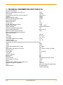
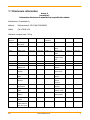
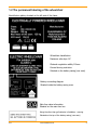
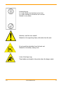
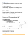
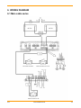
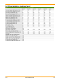
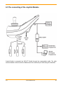
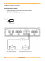
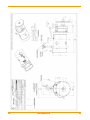
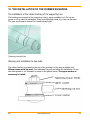
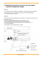
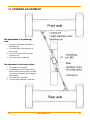
SERVICE MANUAL
Read the manual carefully.
For more detailed information please contact us.
Chasswheel Ltd
Myllyharjuntie 6
71800 SIILINJÄRVI
Tel. +358 - 0207 559 220
Fax. +358 - 0207 559 221
CONTENTS
CONTENTS................................................................................................................................ 2
1. TECHNICAL INFORMATION CW4 FOUR X DL ........................................................................ 3
1.1
Disclosure information ...................................................................................................... 4
1.2 The permanent labeling of the wheelchair .............................................................................. 5
2.
DECLARATION OF CONFIRMATION ...................................................................................... 7
3.
WARRANTY........................................................................................................................ 8
4.
ROUTINE MAINTENANCE .................................................................................................... 9
4.1 Lubrication ........................................................................................................................ 10
4.2 Torque wrench settings and thread locking .......................................................................... 10
5.
5.2
5.3
5.4
5.5
5.6
PRESENTATION OF ELECTRICAL SYSTEM ........................................................................... 11
Balance adjustment ............................................................................................................ 12
Free-wheeling .................................................................................................................... 12
Battery charging ................................................................................................................ 12
Lightning system................................................................................................................ 12
Driving light lamp replacement
........................................................................ 12
6.
6.1
6.2
6.3
6.5
6.6
WIRING DIAGRAM............................................................................................................ 13
Main cable series ............................................................................................................... 13
Axle cable series ................................................................................................................ 14
Programming, engineer level............................................................................................... 15
The connecting of the Joystick Module ................................................................................. 16
Micro switch connection...................................................................................................... 17
7.
REMOVING AND INSTALLATION OF THE DRIVE MOTORS.................................................... 20
8.
CHANGING THE BALANCE ADJUSTING ACTUATOR .............................................................. 21
9.
SUPPORTING RODS FIXING TO JOINT ARM ....................................................................... 22
10. THE INSTALLATION OF THE RUBBER BUSHINGS ................................................................ 23
11.
REMOVING AND INSTALLATION OF THE GAS SPRING (SUPPORT FRAME-SEAT FRAME).... 24
12.
STEERING ADJUSTMENT ................................................................................................ 25
13.
CHANGING A TYRE ........................................................................................................ 26
DX-2
www.chasswheel.com
2
1. TECHNICAL INFORMATION CW4 FOUR X DL
Wheelchair classification
C
Maximum recommended mass of the user
125kg
Driving speed
10 km/h
Driving distance, depending on drive conditions
approx 35km
Clearance
100mm
Obstacle negotiation ability
100mm
Maximum obstacle negotiation ability
115mm
Slope climbing capacity
20°
Maximum safe slope
10°
Turning radius
1.15m
Turning space (with one reverse)
1.7m
Operating temperature
- 25°C - + 40°C
Charger (standard)
90256 NB Popular 8 A
Maximum permitted charging current
12 A
Weight (including batteries)
approx 130 kg
Mass of the heaviest part of the chair
70kg
(Seat, leg support and batteries detached)
Seat Recaro (standard)
-width
53,2 cm
-seat depth
46 - 51 cm
-back height
76 – 82 cm
-seat surface height at the front edge
57 cm
-seat plane angle
18° - 33°
Transport measurements
(leg support and head rest detached, back rest turned into the front position)
-width
69cm
-length
100cm
-height (varies depending on the seat)
82...89 cm
Tyres
3.00 - 8
Tyre pressure, depending on the model
1,3 - 3,5 bar (130 kPa - 350 kPa)
Light equipment
24V
-driving lights
2 x 2,8 W/LED
-rear lights
24 V
-direction indicators
24 V
Electric system
24V
Main fuse
80A
Driving controller
DX2 REM550 /Dynamic Controls
Driving motors (4 x 250 W)
1000W
Brakes
4 pcs
Standard battery DENKA Gel Battery DEG 12-80
2 pcs
Spindle motor (balance adjustment)
Linak 28 S
Frame
steel, stove enamelled powder paint
Shock absorption
2 shock absorbers,
I steering attenuator
DX-2
www.chasswheel.com
3
1.1 Disclosure information
Annex A
(normative)
Information disclosure in manufacturer’s specification sheets
Manufacturer: Chasswheel Oy
Address:
Myllyharjuntie 6, FIN-71800 SIILINJÄRVI
Model:
CW 4 FOUR X DL
Maximum occupant mass: 125 kg
Standard
Min
Max
reference
7176-5
Standard
Min
Max
10°
21°
390 mm
510 mm
520 mm
600 mm
570 mm
740 mm
reference
Overall lenght
1270 mm
1370 mm
7176-7 1
Seat plane angle
Effective seat
with legrest
7176-5
Overall width
692 mm
692 mm
7176-7 2
7176-5
folded length
1000 mm
1000 mm
7176-7 4
7176-5
folded width
692 mm
692 mm
7176-7 5
depth
Effective seat
width
Seat surface
height at front
end
7176-5
folded height
820 mm
7176-7 6
backrest angle
Total mass
820 mm
130 kg
7176-7 7
backrest height
500 mm
600 mm
mass of the
80 kg
7176-7 11
footrest to seat
400 mm
500 mm
90°
160°
150 mm
310 mm
180 mm
500 mm
heaviest part
7176-1
static stability
distance
25°
7176-7 15
25°
7176-7 16
15°
7176-7 22
downhill
7176-1
static stability
static stability
leg to seat
surface angle
uphill
7176-1
50
armrest to seat
distance
sideways
Front location of
armrest
structure
7176-4
energy
35 km
handrim
consumption
7176-2
dynamic stability
diameter
10°
Horizontal
uphill
7176-10
Obstacle
location of axle
115 mm
7176-5
climbing
7176-6
maximum speed
Minimum
1150 mm
turning radius
10 km/h
forward
7176-6
minimum
1000 mm
braking distance
from max speed
DX-2
www.chasswheel.com
4
1.2 The permanent labeling of the wheelchair
Identification plates, situated on the left side of the frame
Wheelchair classification
Maximum safe slope 10°
Obstacle negotiation ability 100mm
General driving restriction
Situated on the battery casing (rear case)
Battery connecting diagram
Situated inside the battery casing cover
Main fuse value information
Situated on the main fuse box
Using the other than gel batteries is forbidden - warning
Situated on the top of the battery casing (rear case)
DX-2
www.chasswheel.com
5
Freewheeling sign
D = breaks locked, the wheelchair can be driven
N = breaks released, the wheelchair can be towed
Situated in every fender
Attention, read the user manual
Situated on the supporting frame, both sides from the seat
Do not push the wheelchair from the back rest.
Situated on the battery casing cover
A risk of the finger trap,
These labels are situated in the points where the danger exists.
DX-2
www.chasswheel.com
6
2. DECLARATION OF CONFIRMATION
CE
The Manufacturer:
Chasswheel Ltd
Myllyharjuntie 6
71800 SIILINJÄRVI
FINLAND
declares that the CHASSWHEEL CW4 FOUR X DL electrically powered wheelchair
conforms to the following standard requirements
9 COUNCIL DIRECTIVE 93/42/EEC
of 14 June 1993
concerning medical devices
Applicable Standards:
EN 12184
3/42/EEC
EN 12184
Siilinjärvi 31.8.2011
Risto Heikkinen
Managing Director
DX-2
www.chasswheel.com
7
3. WARRANTY
Chasswheel Oy grants a two (2) year warranty for the CHASSWHEEL CW4 FOUR X DL electric
wheelchair’s frame and chassis, the driving control system, driving motors, and the seat. Batteries
and charging appliances are not included in the warranty. On every wheelchair there is a model plate
which shows a unique serial number.
This warranty covers faults that occur in normal operation of the wheelchair. The warranty does not
cover faults caused by normal wear and improper or lack of maintenance as indicated in the owner's
manual and the service instructions.
Furthermore, the warranty does not cover faults originating from overloading or incorrect
programming. Normal wear occurs in parts such as tyres, rubber mountings, leaf springs, joints and
slide surfaces. Increased noise of the driving motors is also caused by normal wear.
Indirect expenses incurred in dealing with faults are not included in the warranty.
DX-2
www.chasswheel.com
8
4. ROUTINE MAINTENANCE
The maintenance period is dependent on the usin circumtances. The period should not be more than
one year. However, it is necessary to observe the condition of the wheelchair all the time.
During the routine maintenance the following objects must be checked:
- the condition of tyres and their fixing
- the function of the parking brakes and the releasers
- the tightness of the screws ( see page 13 for more information )
- the weariness of the joints
- the condition of the electrical cabling is checked visually
- all functions of the driving controller
- the condition of the charging socket
the condition of the joystick rubber gaiter
- the condition of the batteries and greasing of the joints
-
testing the condition of the motors
tyre pressure, max. tyre pressure given on tyres label
A test drive should be done during the maintenance to observe the condition of the drive motors
(veering, reduced efficiency, noise etc. )
DX-2
www.chasswheel.com
9
4.1 Lubrication
Lubrication object
Interval
Lubricant
Upper joints bearing of the
axle
At least once a year
lubricating oil
frame
in connection with assembly
graphite Vaseline
and / or
lubricating oil
Steering rod end rubber
bushing
In connection with service of the
releaser
silicon based crease or oil
Slide rail of the supporting
4.2 Torque wrench settings and thread locking
Moment
Attachment
Nm
Thread locking
The spring attachment in the frame
35
Hard
Lower bearing attachment in the axle
35
Nylock
Lower bearing attachment in the holder
35
Nylock
Holder attachment in the spring
35
Nylock
Supporting rods attachment to joint arm
50
Medium Hard
Supporting rods attachment to axles
35
Medium Hard
Steering joint bearings attachment to axles
35
Medium Hard
Attachment of drive motors
8
Medium Hard
Joint arm attachment to frame
50
Medium Hard
Attachment of the steering damper
35
Medium Hard
Attachment of the slide bracket to the slide
8
Medium Hard
Attachment of the slide bracket to the
Medium Hard
frame
12
Attachment of the bearing bracket to the
seat frame
12
Attachment of the seat, M6
10
( some seat screws may have self locking
type thread ) M8
DX-2
Medium Hard
Medium Hard
Medium Hard
35
www.chasswheel.com
10
5. PRESENTATION OF ELECTRICAL SYSTEM
General description
The nominal voltage of the electric system is 24 V for drive motors and actuator(s), the
lightning system voltage is 24 V. The power source of the system is two series connected
gel batteries, which are charged by a separate charger. There are four drive motors
and an actuator for balance adjustment. There are four driving motors and one actuator for the
sense of gravity.
Driving controller system
The driving controller of the wheelchair is Dynamic Controls DX2 –system, which consists
of the following parts:
-
DX2-Power Module, including power electronics, programmed values, limits
and lights.
Joystick Module DX2-REM550, including the joystick, controls and a
socket for charger and programmer.
DX2-ACT Module, including connecting points for actuator(s) and limits.
Joystick Cable, this is a cable between the Power Module and the Joystick
Module.
The connection of the driving controller
The wheelchair has four drive motors which are coupled crosswise. The right channel of
the controller is coupled to the motor circuit, which consist of a parallel coupled front
right and rear left drive motor. Correspondingly, the left channel of the controller is
coupled to the motor circuit, which consist of parallel coupled front left and rear right
drive motor. By that coupling arrangement the driving controller is made to suit the
chassis structure based on the turning of the axles. The driving technique of the
wheelchair differs from the driving technique of a two-wheel drive wheelchair. There are
many programming possibilities in the driving controller, of which some has to be installed
at the factory and the rest can be altered, when the wheelchair has to be adjusted to suit the user.
DX-2
www.chasswheel.com
11
5.1 Drive motors
The wheelchair has four permanent magnetized 24 V motors similar to each other with
gear and parking brake.
5.2 Balance adjustment
The balance adjustment is made by an actuator which moves the supporting frame in
relation to the main frame. When the supporting frame is moved backwards, the seat
starts to lean back at a certain stake. The actuator is controlled by the joystick, when the
actuator adjusting mode is selected.
5.3 Free-wheeling
If the wheelchair must be pushed, the parking brakes are released by turning the lever in
the middle of both axles about 90° counter clockwise (from ON to OFF position). A micro
switch in connection with the releasing device breaks the parking brake circuit and
prevents the driving of the wheelchair in brake less state.
5.4 Battery charging
The batteries are charged by a separate charger which is connected to the XLR-connector
in the front of the Joystick Module. Maximum charging current is 12 A.
5.5 Lightning system
The wheelchair has a lighting system (24 V), which includes following:
-
2 white driving lights in front
2 red rear lights, LED
2 orange direction indicators, LED
Bulbs renewal
Driving lights:
24 V
2,8 W
Direction indicator:
maintenance free
Rear lights:
maintenance free
E 10
5.6 Driving light lamp replacement (Picture 1)
Picture 1.
1. The small screw behind the lamp is loosened.
2. The driving light is turned counter clockwise, when the lantern is got off from its base.
3. The lamp is removed and replaced with new lamp.
4. The reassembly is done in the opposite order.
Other lighting devices are maintenance free LED-lights.
DX-2
www.chasswheel.com
12
6. WIRING DIAGRAM
6.1 Main cable series
DX-2
www.chasswheel.com
13
6.2 Axle cable series
DX-2
www.chasswheel.com
14
6.3 Programming, engineer level
DX-2
www.chasswheel.com
15
6.5 The connecting of the Joystick Module
Joystick Module is connected into DX2-ACT Module through the communication cable. The cable
must be situated so that it cannot be flattened and not be aimed at pull while using the wheelchair.
DX-2
www.chasswheel.com
16
6.6 Micro switch connection
Speed limit switch for turning
-
located in the frame, on the right side of the control rod’s guide
limits speed in half (5km/h)
if the cable drops off, only limited speed is in use
Connection:
Micro switch
DX-2
www.chasswheel.com
17
6.7 Drive motors
DX-2
www.chasswheel.com
18
DX-2
www.chasswheel.com
19
7. REMOVING AND INSTALLATION OF THE DRIVE MOTORS
Removing:
1. The battery cable is disconnected
2. The axle of the motor that is under removing is supported underside.
3. Release the tyre from the motor (6 x hexagonal bolt, 6 mm wrench)
4. Release the fender (3 x hexagonal head bolt, 10 mm wrench)
5. Release the fender holder
6. Release the protective casing from the frame(4 x cross mouthed srew)
Release the seat if necessary.
7. Release the connector coming from the motor, remove the cable ties.
8. Release the remaining motor’s fastening srews.
9. Motor is pulled off from the axle
Motor installation:
1. Check that the breaks are released and locked while turning the break lever.
2. Set the motor on the axle.
3. Fasten motor’s screws, use middle hard thread locking, do not over stretch.
4. Install the fender holder and fasten the last motor connector srew
5. Connect the motor connector.
6. Install the protective caising.
7. Fasten the motor’s electric cable on the supporting shaft with cable ties.
8. Install the fender.
9. Install the tyre.
10. Remove the supporting.
11. Connect the battery and check the function.
12. After changing the motor there could appear uneven streering while driving the wheelchair.
This could be fixed by changing ”STEER CORRECT”- settings. For changing the setting is
needed different programming device.
DX-2
www.chasswheel.com
20
8. CHANGING THE BALANCE ADJUSTING ACTUATOR
Removing of the actuator:
1. Remove the seat by opening 4 screws that holds the seat on the seat frame.
2. If the actuator is working, it is driven to middle position, when the gas spring tension is
lowest.
3. One battery terminal is detached.
4. Disconnect the actuator cable from the cable series, connector 2.
5. Remove the retaining cable tie from the back tube of the seat frame.
6. Open actuators fastening screws.
7. Release the actuator from the holder
Installation of the actuator:
1. Install rear part of the actuator in to the holder and stretch the screw and the nut.
2. Screw the actuators axle so that the axle’s hole and supporting frames retaining hole are
concentric.
3. The axel’s slot is pushed in to the mounting point and holes are aimed at concentric by using
for exemple a mandrel with help.
4. Tight the front end screw and the nut.
5. Attach the actuator’s cable with cable tie into the hole in the seat frame.
6. Connect the actuator’s cable in the cable series, connector 2.
7. Connect the battery and check the function.
8. Connect the battery and check the function
9. Check that the cables and pipes moves properly during motion.
10. Install the seat back.
DX-2
www.chasswheel.com
21
9. SUPPORTING RODS FIXING TO JOINT ARM
10.
The side way adjustment of
the seat frame
If the seat position is not correct,
the adjusting nut is turned until
the right position is found. After
that the locking nuts are tightened
and the bump travel is checked.
The adjustment of the bumb
travel
When the wheelchair is at flat plane,
the clearance is adjusted with
suitable gauge ( 3 mm ).
DX-2
www.chasswheel.com
22
10. THE INSTALLATION OF THE RUBBER BUSHINGS
The installation of the rubber bushing of the supporting rod
The bushings are pressed to the supporting rods by using a suitable tool. Do not use
grease or oil to ease the installation. Some non-disturbing liquid, e.g. soap can be used.
The joint arm thread is cleaned for thread locking liquid.
Tightening torque 60 Nm
Steering rods installation to axle tube
The rubber bushing is pressed to the end of the steering rod by using a suitable tool.
Silicon crease must be used. This lubricates the joint and eases the installation. Do not
use other grease or oil. Assembly is shown in the picture below. The upper washer is
necessary to install.
DX-2
www.chasswheel.com
23
11. REMOVING AND INSTALLATION OF THE GAS SPRING
(SUPPORT FRAME-SEAT FRAME)
Removing:
1. The actuator is driven to middle or front position so the gas spring has lowest tension
2. The front fixing screw of the gas spring is loosened so the tension disappears
3. The rear fixing screw is loosened.
Installation:
1. The rear end of the gas spring is fitted to seat frame. This is a joint, so the screw is not
fully tightened ( fig. 3 )
2. The front mounting bracket is fitted to supporting frame ( fig. 1 )
3. The screw is fitted to the bracket with front end of the gas spring
4. The bracket Is turned to horizontal position with 10 mm spanner ( fig. 2 )
5. The screw is tightened
6. The actuator is driven and the function is tested.
DX-2
www.chasswheel.com
24
12. STEERING ADJUSTMENT
The adjustment of the steering
rods:
1. The slide is centralized and locked by
centralizing pin
2. The locking nuts of the steering rods
are loosened
3. The rods are turned until their angle
to frame is 90°
4. The locking nuts are tightened
The adjustment of the turning radius:
1. The locking nut is loosened
2. The adjusting screw of turning radius is
turned, until the turning radius is suitable
( the axle is not touching the leg support
with turnings )
3. The locking nut is tightened
4. The other side is adjusted in same way
DX-2
www.chasswheel.com
25
13. CHANGING A TYRE
The rim is attached to the motors hub with five coach screws, tool size 6mm. Support the
axle so that the tyre is off the ground. After that release the air pressure from the tyre.
When and only when you have done this open the screws and take of the tyre. Both halfs of
the rim are attachet to each other with screws, which you are not allowed to open until you
have released the air pressure.
Assembling the wheel with tyre.
install inner tube into the outer tyre and install this packet onto the rim half. Attach both rim
halfs together with screws. Pay attention that the inner tube does not squeeze between the
rim halfs. Now fill the tyre alittle bit (0.5bar) to get the inner tube straight. After this install
the tyre onto the motors hub with coach screws. When tyre is attached to the motor, fill up
the tyre (approx. 3bar is reasonable). After this remove lifting equipment and the chair is
ready to drive again.
DX-2
www.chasswheel.com
26


![[ user manual ] - Electro Optical Components, Inc.](http://vs1.manualzilla.com/store/data/005883576_1-0c36e07c3044c4bd3e113418af6fccd7-150x150.png)


![[ user manual ]](http://vs1.manualzilla.com/store/data/006917286_1-ab1d9edbe86470fcfa5481380fd001da-150x150.png)

![[ user manual ]](http://vs1.manualzilla.com/store/data/006920003_1-d680b577f9aafbf5352b2591a509e95d-150x150.png)