1
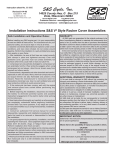
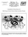
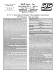
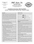
1
Instruction No. 00-4354
7-17-00
-Copyright © 2000
by S&S Cycle, Inc.
All rights reserved. Printed in the U.S.A.
®
S&S Cycle, Inc.
14025 County Hwy. G P.O. Box 215
Viola, Wisconsin 54664
Phone 608-627-1497
Fax 608-627-1488
Email: sstech@sscycle.com
sscust@sscycle.com
Website: www.sscycle.com
Die-Cast Rocker Cover Instructions For Twin Cams & Evolutions
Safe Installation and Operation Rules:
WARRANTY:
Before installing any S&S engine part, it is your responsibility
to read and follow all instructions. The rules below are for your
personal safety, and must be kept in mind at all times.
● Gasoline is extremely flammable and explosive under
certain conditions, and toxic when inhaled. Do not smoke
around gasoline. Perform the installation in a well-ventilated
area away from sparks or open flame.
● After installation, be sure all fuel lines are routed correctly
with clamps in place and tightened securely. Even with
protective cover, gas lines must not contact extremely hot
surfaces where they could melt or leak and catch fire.
● Compressed air and particles dislodged by compressed air
are potentially harmful. Wear protective goggles when using
compressed air and always direct the air stream away from
yourself and others nearby.
● Some solvents, degreasers and other chemicals are
harmful, especially to skin and eyes. Many chemical
compounds such as lacquer thinner are also flammable and
present a fire hazard. Read the manufacturer’s instruction label
for precautions and proper use. Use in a well ventilated area
and wear protective clothing to avoid personal injury.
● If the motorcycle has been running, wait until the engine
and exhaust pipes have cooled before performing any
mechanical work.
● Before beginning the installation, disconnect and remove
the battery to eliminate potential sparks and possible
inadvertent engagement of the electric starter while working
on the motorcycle.
● Read instructions thoroughly and carefully so all procedures
are completely understood before beginning installation.
Contact S&S if you have questions, if any steps are unclear,
or if any abnormalities occur during final assembly, installation,
or operation.
● Consult an authorized H-D service manual for correct
disassembly, reassembly, and installation procedures for any
parts that need to be removed or disassembled to facilitate
the installation.
● Use good judgment during assembly, installation, and when
operating the motorcycle. Good judgment begins with a clear
head. Don’t let alcohol, drugs, or fatigue impair judgment.
Perform installation when fresh and alert.
● For optimum performance and safety and to minimize
potential damage to the cylinder heads or other components,
use correct hardware and follow procedures outlined in S&S
instructions and authorized H-D service manual.
● Motorcycle exhaust fumes are toxic and must not be inhaled.
Run motorcycle only in a well ventilated area where fumes
can dissipate.
All S&S parts are guaranteed to the original purchaser to be
free of manufacturing defects in materials and workmanship for a
period of six (6) months from the date of purchase. Merchandise
that fails to conform to these conditions will be repaired or replaced
at S&S’s option if the parts are returned to S&S by the purchaser
within the 6 month warranty period or within 10 days thereafter.
In the event warranty service is required, the original purchaser
must notify S&S of the problem immediately. Some problems can
be rectified by a telephone call and need no further action. A part
that is suspected of being defective must not be replaced without
prior authorization from S&S. If it is deemed necessary for S&S to
make an evaluation to determine whether the part was defective, it
must be packaged properly to avoid further damage, and be
returned prepaid to S&S with a copy of the original invoice of
purchase and a detailed letter outlining the nature of the problem,
how the part was used, and the circumstances at the time of failure.
If after an evaluation was made by S&S and the part was found to
be defective, repair, replacement, or refund will be granted.
ADDITIONAL WARRANTY PROVISIONS:
(1) No part shall be returned to S&S without first contacting the
company and obtaining a Return Authorization (RA) number.
(2) S&S shall have no obligation in the event an S&S part is modified
by any other person or organization, or if another manufacturer’s
part is substituted for one provided by S&S.
(3) S&S shall have no obligation if an S&S part becomes defective
in whole or in part as a result of improper installation, improper
break-in or maintenance, improper use, abnormal operation, or
any other misuse or mistreatment.
(4) S&S shall not be liable for any consequential or incidental
damages resulting from the failure of an S&S part, the breech of
any warranties, the failure to deliver, delay in delivery, delivery in
non-conforming condition, or for any other breach of contract or
duty between S&S and a customer.
(5) S&S parts are designed exclusively for use on Harley-Davidson
motorcycles. S&S shall have no warranty or liability obligation if
an S&S part is used in any other application.
IMPORTANT NOTICE:
Statements in this instruction sheet preceded by the following words
are of special significance:
WARNING
Means there is the possibility of injury to yourself or others.
CAUTION
Means there is the possibility of damage to the motorcycle or
a component.
NOTE
Other information of particular importance has been placed in italic
type.
S&S urges you to take special notice of these advisories.
2
Introduction
With minor exceptions, S&S die-cast rocker cover
kits for Twin Cams and Evos are identical. Mounting
holes are larger in bases for Twin Cams and in slightly
different locations. Because of the different vent
systems and mounting-bolt patterns, different rocker
housing bases, rocker supports and rocker housing
base gaskets are required for the two engines.
Removal of existing rocker covers and installation
of S&S Die-Cast covers is similar for Twin Cams
and Evos. Steps 4, 7, and 9 involve procedures or
components that apply only to one model or the
other; where applicable, procedures and
illustrations are clearly designated “Twin Cam” or
“Evo.” Otherwise, Twin Cam and Evo installations
are identical. S&S recommends that the installer
become thoroughly familiar with the “Top End
Overhaul Procedure” section in an appropriate Twin
Cam or Evo/V2 H-D service manual and refer to
this section as required.
CAUTIONS
● Failure to establish correct clearances can
result in extensive engine damage not covered
under warranty.
● It is the installer’s responsibility to use
Loctite according to directions printed on the
container, and to tighten fasteners to correct
torque values. Failure to install fasteners
correctly may result in the fastener vibrating
loose and causing extensive engine damage
not covered under warranty.
WARNING – Gasoline, lacquer thinner, and
many solvents are extremely flammable. Fumes
may be explosive and toxic if inhaled. Read and
follow the manufacturers’ instructions if
applicable, and use these materials only in a
well ventilated area away from sparks and open
flame.
Installation
S&S wrench set # 53-0040 will prove helpful when
installing S&S rocker covers. As an alternative,
conventional Allen wrenches can be shortened by
grinding. Otherwise, the motorcycle frame may
interfere with the tightening of some fasteners. S&S
strongly recommends the use of a torque wrench
and Loctite 242 (included) on all fasteners.
S&S rocker covers accept valve springs up to
1.660” O.D. with no modification. In most instances,
they will accept valve lifts to .710” without
modification. It remains the installer’s responsibility
to confirm all clearances. For your own protection
and to prevent damage to your motorcycle during
the installation, thoroughly familiarize yourself with
these instructions before proceeding.
NOTES
● Threads should be cleaned with Loctite primer
or an equivalent before applying Loctite; S&S has
used lacquer thinner with excellent results.
● The installer must check clearances between the
valve spring/top collar and rocker cover housing as
well as between the rocker arm and top cover. These
procedures are described in Steps10 and 16.
● The cylinder head must be correctly prepared
for higher than stock lifts according to the cam
manufacturer’s instructions.
1. Wash motorcycle, taking special care to remove
dirt from engine and surrounding area. Remove
gas tanks and clean engine and surrounding
area with compressed air. Disconnect battery,
ground cable first, and remove from motorcycle.
CAUTION - Dirt and other contaminants can
cause extensive damage if allowed to fall into
engine.
WARNINGS
● Sparks from motorcycle electrical system can
ignite gasoline fumes, resulting in an explosion.
Removing battery eliminates the possibilities of
explosion and injury arising from inadvertent
activation of the electric starter.
● High-pressure air is potentially hazardous.
Wear eye protection during use and direct air
stream away from face and others nearby.
2. Remove OEM top rocker cover. Remove
pushrod cover retainers from front cylinder
pushrods and collapse pushrod covers.
3. Remove spark plugs, place motorcycle in fifth
gear, and turn wheel to rotate engine and place
intake and exhaust pushrods/lifters for front
3
cylinder at lowest point on cam; front piston will
be at TDC on Compression stroke with
pushrods/lifters at lowest point. Confirm that
both pushrods can be rotated with light finger
pressure. See Picture 1.
CAUTION – Failure to confirm correct pushrod
position can result in damage to rocker arm
support plates and other parts.
4. Remove existing components
A. Twin Cam:
1. Remove breather and baffle assembly.
See Picture 2.
2. Gradually loosen rocker arm support bolts
in sequence shown. See Figure 1.
Loosen rocker support bolts in 1⁄4 -turn
increments for first 3⁄4 turn, then remove.
3. Remove rocker arms/support assembly
from cylinder head. Loosen bolts in 1⁄4 -turn
increments for first 3⁄4 turn, then remove
bolts and remove rocker housing from
cylinder head.
B. Evo:
1. Gradually loosen and remove five rocker
housing screws. Loosen screws in 1⁄4 -turn
increments for first 3⁄4 turn, then remove.
2. Remove rocker housing with rocker
arms and shafts from cylinder head.
5. Taking care to keep parts in same order as
removed, remove rocker shafts and rocker arms
from support (Twin Cam) or lower rocker
housing (Evo). Mark components according to
Picture 2 (Twin Cam Only)
location: “front intake,” etc., so they can be
returned to their original locations.
6. Remove oil and any remaining gasket material
from cylinder head gasket surface. Clean
gasket surface with lacquer thinner.
WARNING – Lacquer thinner is extremely
flammable, potentially explosive, and the fumes
toxic when inhaled. Read manufacturer’s
cautions on container and use only in a wellventilated area away from sparks and open
flame.
7. Place lower rocker housing gasket(s) supplied
in kit on cylinder head.
A. Twin Cam: One gasket required. Gasket
must be positioned to cover breather
channel in cylinder head. If necessary, use
a small amount of gasket adhesive or
Driveside
1
4
3
Front
Picture 1 (Twin Cam & Evo)
2
Camside
Figure 1 (Twin Cam & Evo)
4
Picture 3A (Correct)
NOTE – It is possible to install gasket incorrectly.
Before proceeding, confirm that gasket is placed
correctly and covers breather channel. See
Pictures 3A (TC Only) & 3B (TC Only).
B. Evo: Two gaskets required. Factory-applied
silicone beads should face up. If necessary,
use a small amount of gasket adhesive or
sealant to hold gaskets in place. Otherwise,
gaskets should be installed dry.
8. Prepare lower rocker housing screws according
to instructions on Loctite container and apply thin
film of Loctite to threads.
A. Twin Cam: Lower rocker housing screws are
5
⁄16 -18 x 3⁄4 (6 ea.)
head. Tighten screws two turns to hold
rocker housing and gasket in place.
2. Install four remaining rocker housing
screws. Gradually tighten six screws to
15-18 ft-lbs. using sequence illustrated
in Figure 2.
3. Measure clearance between rocker
housing and valve spring. See Picture 4.
Minimum is .025”. If necessary, loosen
screws and reposition housing to increase
clearance, then retighten screws.
4. Place o-ring in center of rocker housing.
B. Evo:
1. Place two rocker housing screws in left
(drive side) holes of rocker housing and
place housing on cylinder head.
2. Start two 5⁄16 -18 x 2 1⁄2 hex head bolts in
right (cam side) rocker support holes to
temporarily hold cam-side rocker
housing gasket in position. Install two
NOTE – Screws for remaining holes in bottom
of Evo and TC rocker housing base will be
installed in Step 14-A.
B. Evo: Lower rocker housing screws are
1
⁄ 4 -20 x 3⁄ 4 (4 ea.)
Driveside
3
2
NOTE – Screw for center right bolt hole in Evo
engines will be installed in Step 14-B.
5
6
9. Install lower rocker housing on cylinder head.
A. Twin Cam:
1. Place rocker housing screws in front
and rear left (drive side) holes of rocker
housing and place housing on cylinder
1
4
Camside
Figure 2 (Twin Cam Only)
Front
sealant to hold gasket in place. Otherwise,
gasket should be installed dry.
Picture 3B (Incorrect)
5
Picture 4 (Twin Cam & Evo)
remaining rocker housing screws.
Gradually tighten four 1⁄4 -20 x 3⁄4 screws
to 10-13 ft-lbs. Remove hex head bolts.
3. Measure clearance between rocker
housing and valve spring. See Picture 4.
Minimum is .025”. If necessary, loosen
screws and reposition housing to increase
clearance, then retighten screws.
4. Place o-ring in center of rocker housing.
10. Inspect rocker shafts for burrs and excessive
wear; deburr or replace as necessary. Lubricate
rocker shafts with assembly lube, place rocker
arms in support, and slide shafts through
supports and rocker arms. Reliefs in shafts must
face away from center of engine and align with
right (cam side) bolt holes. See Picture 5.
11. Check rocker arm endplay by sliding rocker arm
as far to one side as possible and measuring
gap between rocker arm and support on
opposite end. Acceptable endplay is .001” to
.012”. If endplay is insufficient, carefully remove
material from end of rocker arm to achieve
correct endplay. Leave a smooth, nonabrasive
surface.
12. Prepare rocker support bolts according to
instructions on Loctite container and apply thin
film of Loctite to threads. Insert two 5⁄16 -18 x 2 1⁄4”
socket head bolts and washers in holes in left
(drive) side of support and two 5⁄16 -18 x 2 1⁄2” hex
head bolts in holes in right (cam) side of support.
Picture 5 (Twin Cam & Evo)
13. Place rocker arm support assembly with rockers
in rocker housing. Align pushrod ends with
sockets in rockers and gradually tighten four
support bolts to 15-18 ft-lbs. according to
sequence shown. See Figure 1.
14. Install remaining rocker support bolt(s).
A. Twin Cam: Prepare one 1⁄4 -20 x 1 socket
head bolt and one 1⁄4 -20 x 2 socket head
bolt for Loctite and apply thin film of Loctite
to threads. Install washers on both bolts.
Insert 1⁄4 -20 x 1 bolt with washer in center
left side of support and 1⁄4 -20 x 2 bolt with
washer in center right side of support.
Tighten both to 10-13 ft-lbs.
B. Evo: Prepare one 1⁄4 -20 x 2 socket head bolt
for Loctite and apply thin film of Loctite to
threads. Install washer on bolt and inert bolt
with washer in center right hole of support.
Tighten to 10-13 ft-lbs.
NOTE – Hydraulic lifters may take 5-10 minutes
to bleed down after rocker assembly is installed.
Do not rotate engine until pushrods can be turned
with light finger pressure.
CAUTION – Rotating engine before lifters have
bled down can cause extensive engine damage.
15. Confirm clearance between rocker arm and top
rocker cover by applying layer of clay at least
.060” thick to areas of cover that rocker arms
will come closest to at maximum lift. Temporarily
6
17. Install one flat and one rubber-covered metal
washer on each of six 1⁄4 -20 x 3⁄4 rocker cover
screws.
2
5
3
NOTE – Install flat washer on screw first. Rubbercovered washer goes between flat washer and
rocker cover.
4
6
1
18. Install rocker cover and gradually tighten screws
to 10-13 ft-lbs. in sequence shown. See Figure 3.
19. After confirming that pushrods turn with light
finger pressure, extend pushrod tubes and
replace retainer clips.
Figure 3 (Twin Cam & Evo)
install covers with four screws and rotate engine
through two complete revolutions. Carefully
remove covers and examine clay. Layer of clay
above rocker arm must remain at least .060”
thick. If dented, indentation must leave at least
.060” of clay between rocker arm and cover.
Remove clay and thoroughly clean rocker and
cover with clean, lint-free cloth.
16. Place rocker cover seal and o-ring in position
on rocker housing.
20. Remove retainers and collapse covers of rear
cylinder pushrods. Rotate engine to place
pushrods at lowest point on cam with rear piston
at TDC on compression stroke. Repeat rocker
cover removal and installation procedure for
rear cylinder.
21. Replace any parts removed for rocker cover
installation, start motorcycle and inspect for gas
and oil leaks.
Safe riding!
7
V2-Style
Die Cast Rocker Cover V2-Style and Related Parts
1. Screw, Socket Head 1/4-20 x 3/4 ..................... 50-0067
2. Washer, Flat 1/4 (14) ....................................... 50-7017
3. Washer, Fiber 1/4 (12) ..................................... 50-7015
4. Seal, O-ring (4) ................................................ 50-8044
5. Screw, Socket Head 1/4-20 x 2 (4) ................... 50-0013
6. Screw, Hex Flange Head 5/16-18 x 2-1/4 (4) ... 50-0132
7. Support, Rocker Arm ....................................... 90-4094
8. Gasket, Rocker Housing (Camside) (2) ............ 90-4058
9. Gasket, Rocker Housing (Driveside) (2) ........... 90-4059
10. Housing, Rocker (Chrome) (2) ......................... 90-4088
Housing, Rocker - Polished) (2) Not shown ..... 90-4086
Housing, Rocker - Plain) (2) Not shown .......... 90-4092
11. Screw, Socket Head 1/4-20 x 3/4 (8) ................ 50-0066
12. Seal, Rocker Cover (2) .................................... 90-4079
13. Washer, Flat 5/16 (4) ....................................... 50-7056
14. Screw, Socket Head 5/16-18 x 2-1/4 ................ 50-0115
15. Cover, Rocker - Chrome (2) ............................. 90-4089
Cover, Rocker - Polished (2) ............................ 90-4087
Cover, Rocker - Plain (2) .................................. 90-4093
* Kit, Rocker Cover - Chrome Not shown ........... 90-4095
* Kit, Rocker Cover - Polished Not shown .......... 90-4090
* Kit, Rocker Cover - Plain Not shown ................ 90-4083
* Gasket Set Not shown ..................................... 90-4091
Twin Cam-Style
Die Cast Rocker Cover Twin Cam-Style & Related Parts
1. Screw, Socket Head 1/4-20 x 3/4 ..................... 50-0067
2. Washer, Flat 1/4 (16) ....................................... 50-7017
3. Washer, Fiber 1/4 (12) ..................................... 50-7015
4. Seal, O-ring (4) ................................................ 50-8044
5. Screw, Socket Head 1/4-20 x 1 (2) ................... 50-0084
6. Screw, Socket Head 1/4-20 x 2 (2) ................... 50-0013
7. Screw, Hex Flange Head 5/16-18 x 2-1/4 (4) ... 50-0132
8. Support, Rocker Arm ....................................... 90-4109
9. Gasket, Rocker Housing .................................. 90-4071
10. Housing, Rocker (Chrome) (2) ......................... 90-4107
Housing, Rocker - Polished) (2) ....................... 90-4106
Housing, Rocker - Plain) (2) ............................. 90-4108
11. Screw, Socket Head 1/4-20 x 3/4 (8) ................ 50-0099
12. Seal, Rocker Cover (2) .................................... 90-4079
13. Washer, Flat 5/16 (4) ....................................... 50-7056
14. Screw, Socket Head 5/16-18 x 2-1/4 ................ 50-0115
15. Cover, Rocker - Chrome (2) ............................. 90-4089
Cover, Rocker - Polished (2) ............................ 90-4087
Cover, Rocker - Plain (2 ................................... 90-4093
* Kit, Rocker Cover - Chrome Not shown ........... 90-4110
* Kit, Rocker Cover - Polished Not shown .......... 90-4106
* Kit, Rocker Cover - Plain Not shown ................ 90-4108
* Gasket Set Not shown ..................................... 90-4111
8