Download ONE MORE TIME CD


Transcript
22
R
ONE MORE TIME CD
WARNING! Although the beam emitted by the laser diodes is nearly invisible, it may cause severe damage to
the human eye. Use an infrared indicator to check the laser beam.
CLASS 1
LASER PRODUCT
3122 110 03420
ATTENTION!
The CD mechanism and many ICs are extremely susceptible to electrostatic discharges. The photo diodes
and the laser diode are more sensitive to discharges than MOS ICs. Careless handling may immediately destroy components or can drastically reduce life expectancy of these components so that it will lead to failure after several weeks or even months of use.
Before you touch the player, discharge your hands and tools by touching a grounded metal part of the jukebox,
such as the amplifier or the mechanism chassis. Make sure that you are connected via a wrist wrap with resistance to the same potential as the chassis of the jukebox. Keep parts and tools at the same potential.
If you remove the player in case of repair or for transport, short the harness with a short circuit plug.
When repairing, observe all valid safety rules. Do not change the original condition of the jukebox. Use original
spare parts only.
ESD
This manual belongs to machines equipped with program versiones 4.09 (or higher).
Subject to alterations.
1
Unpacking . . . . . . . . . . . . . . . . . . . . . . . . . . . . . . . . . . . . . . . . . . . . . . . . . . . . . . . . 5
1.1
Unlocking . . . . . . . . . . . . . . . . . . . . . . . . . . . . . . . . . . . . . . . . . . . . . . . . . . . . . . . . . . . . . . . . . . . . . . . . 5
1.2
Removal of mechanism shipping guards . . . . . . . . . . . . . . . . . . . . . . . . . . . . . . . . . . . . . . . . . . . . . . 5
1.3
Removal of motor book shipping guards . . . . . . . . . . . . . . . . . . . . . . . . . . . . . . . . . . . . . . . . . . . . . . 6
1.4
Power on. . . . . . . . . . . . . . . . . . . . . . . . . . . . . . . . . . . . . . . . . . . . . . . . . . . . . . . . . . . . . . . . . . . . . . . . . 6
2
Loading compact discs . . . . . . . . . . . . . . . . . . . . . . . . . . . . . . . . . . . . . . . . . . . . . 7
2.1
CD handling precautions - CD and player cleaning . . . . . . . . . . . . . . . . . . . . . . . . . . . . . . . . . . . . . . 7
2.2
Inserting CDs . . . . . . . . . . . . . . . . . . . . . . . . . . . . . . . . . . . . . . . . . . . . . . . . . . . . . . . . . . . . . . . . . . . . . 8
2.3
Programming number of CDs in the carrier . . . . . . . . . . . . . . . . . . . . . . . . . . . . . . . . . . . . . . . . . . . . 9
3
Coin operation or free play? . . . . . . . . . . . . . . . . . . . . . . . . . . . . . . . . . . . . . . . . 10
3.1
Coin operation and coin return . . . . . . . . . . . . . . . . . . . . . . . . . . . . . . . . . . . . . . . . . . . . . . . . . . . . . 10
3.2
Price settings . . . . . . . . . . . . . . . . . . . . . . . . . . . . . . . . . . . . . . . . . . . . . . . . . . . . . . . . . . . . . . . . . . . . 10
3.3
Examples . . . . . . . . . . . . . . . . . . . . . . . . . . . . . . . . . . . . . . . . . . . . . . . . . . . . . . . . . . . . . . . . . . . . . . . 11
3.4
Color codes of coin input . . . . . . . . . . . . . . . . . . . . . . . . . . . . . . . . . . . . . . . . . . . . . . . . . . . . . . . . . . 11
3.5
Free play . . . . . . . . . . . . . . . . . . . . . . . . . . . . . . . . . . . . . . . . . . . . . . . . . . . . . . . . . . . . . . . . . . . . . . . . 12
3.6
Test credit. . . . . . . . . . . . . . . . . . . . . . . . . . . . . . . . . . . . . . . . . . . . . . . . . . . . . . . . . . . . . . . . . . . . . . . 12
4
Track selection . . . . . . . . . . . . . . . . . . . . . . . . . . . . . . . . . . . . . . . . . . . . . . . . . . . 14
4.1
How to select a track . . . . . . . . . . . . . . . . . . . . . . . . . . . . . . . . . . . . . . . . . . . . . . . . . . . . . . . . . . . . . . 14
4.2
The button R. . . . . . . . . . . . . . . . . . . . . . . . . . . . . . . . . . . . . . . . . . . . . . . . . . . . . . . . . . . . . . . . . . . . . 14
4.3
The display flashes . . . . . . . . . . . . . . . . . . . . . . . . . . . . . . . . . . . . . . . . . . . . . . . . . . . . . . . . . . . . . . . 14
4.4
I do not like this track - the button CANCEL . . . . . . . . . . . . . . . . . . . . . . . . . . . . . . . . . . . . . . . . . . . 15
5
Volume, sound and balance control . . . . . . . . . . . . . . . . . . . . . . . . . . . . . . . . . . 16
5.1
5.1.1
Volume, sound and balance control - amplifier K99 . . . . . . . . . . . . . . . . . . . . . . . . . . . . . . . . . . . . 16
The infrared remote control . . . . . . . . . . . . . . . . . . . . . . . . . . . . . . . . . . . . . . . . . . . . . . . . . . . . . . . . . . 17
5.2
5.2.1
Volume, sound and balance control - amplifier F91. . . . . . . . . . . . . . . . . . . . . . . . . . . . . . . . . . . . . 18
The infrared remote control . . . . . . . . . . . . . . . . . . . . . . . . . . . . . . . . . . . . . . . . . . . . . . . . . . . . . . . . . . 19
5.3
5.3.1
Pre-settings for volume. . . . . . . . . . . . . . . . . . . . . . . . . . . . . . . . . . . . . . . . . . . . . . . . . . . . . . . . . . . . 20
Pre-settings for bass and treble. . . . . . . . . . . . . . . . . . . . . . . . . . . . . . . . . . . . . . . . . . . . . . . . . . . . . . . 20
6
Programming short view . . . . . . . . . . . . . . . . . . . . . . . . . . . . . . . . . . . . . . . . . . . 21
7
Jukebox programming . . . . . . . . . . . . . . . . . . . . . . . . . . . . . . . . . . . . . . . . . . . . . 22
7.1
Call up service programs . . . . . . . . . . . . . . . . . . . . . . . . . . . . . . . . . . . . . . . . . . . . . . . . . . . . . . . . . . 22
7.2
How to leave service programs . . . . . . . . . . . . . . . . . . . . . . . . . . . . . . . . . . . . . . . . . . . . . . . . . . . . . 22
7.3
7.3.1
7.3.2
7.3.3
Programming of time functions . . . . . . . . . . . . . . . . . . . . . . . . . . . . . . . . . . . . . . . . . . . . . . . . . . . . .
Clock setting, level 2 button 0 . . . . . . . . . . . . . . . . . . . . . . . . . . . . . . . . . . . . . . . . . . . . . . . . . . . . . . . .
Set date, level 2 button 1 . . . . . . . . . . . . . . . . . . . . . . . . . . . . . . . . . . . . . . . . . . . . . . . . . . . . . . . . . . . .
Set year and weekday, level 2 button 2. . . . . . . . . . . . . . . . . . . . . . . . . . . . . . . . . . . . . . . . . . . . . . . . .
7.4
7.4.1
Automatic random select (Playstimulator) . . . . . . . . . . . . . . . . . . . . . . . . . . . . . . . . . . . . . . . . . . . . 24
Programming start and stop time. . . . . . . . . . . . . . . . . . . . . . . . . . . . . . . . . . . . . . . . . . . . . . . . . . . . . . 25
7.5
7.5.1
7.5.2
7.5.3
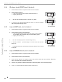
Back Ground Music (BGM) . . . . . . . . . . . . . . . . . . . . . . . . . . . . . . . . . . . . . . . . . . . . . . . . . . . . . . . . .
Number of BGM CDs and repeat time. . . . . . . . . . . . . . . . . . . . . . . . . . . . . . . . . . . . . . . . . . . . . . . . . .
Start position for BGM CDs and configuration. . . . . . . . . . . . . . . . . . . . . . . . . . . . . . . . . . . . . . . . . . . .
BGM time zones at different weekdays . . . . . . . . . . . . . . . . . . . . . . . . . . . . . . . . . . . . . . . . . . . . . . . . .
7.6
7.6.1
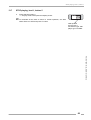
HappyHour pricing (additional bonus plays) . . . . . . . . . . . . . . . . . . . . . . . . . . . . . . . . . . . . . . . . . . 30
Programming of the HappyHour start and stop time, level 2 button 6 . . . . . . . . . . . . . . . . . . . . . . . . . . 30
OMT CD – Edition: 12.05.2005
23
23
23
23
26
27
28
28
1
7.6.2
Programming of the additional bonus plays, level 2 button 7 . . . . . . . . . . . . . . . . . . . . . . . . . . . . . . . . 30
7.7
Number of tracks played successively on the same disc, level 2 button 3 . . . . . . . . . . . . . . . . . . 31
7.8
Album selection and memory reset by power off, level 2 button 9 . . . . . . . . . . . . . . . . . . . . . . . . 32
7.9
Disabling single tracks . . . . . . . . . . . . . . . . . . . . . . . . . . . . . . . . . . . . . . . . . . . . . . . . . . . . . . . . . . . . 33
8
Data retrieval . . . . . . . . . . . . . . . . . . . . . . . . . . . . . . . . . . . . . . . . . . . . . . . . . . . . . 34
8.1
Retrieval of least popular discs (flops), level 1 button 0 . . . . . . . . . . . . . . . . . . . . . . . . . . . . . . . . . 34
8.2
Top Tunes, level 1 button 1 . . . . . . . . . . . . . . . . . . . . . . . . . . . . . . . . . . . . . . . . . . . . . . . . . . . . . . . . 34
8.3
Cash box contents, level 1 button 2 . . . . . . . . . . . . . . . . . . . . . . . . . . . . . . . . . . . . . . . . . . . . . . . . . 35
8.4
Total number of plays, level 1 button 3 . . . . . . . . . . . . . . . . . . . . . . . . . . . . . . . . . . . . . . . . . . . . . . . 35
8.5
CLEAR ALL counters (reset to 0 0 0 0), level 1 button 3 + reset. . . . . . . . . . . . . . . . . . . . . . . . . . . 35
8.6
Memory of not playable CDs, level 1 button 6 . . . . . . . . . . . . . . . . . . . . . . . . . . . . . . . . . . . . . . . . . 35
9
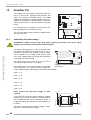
Amplifier K99 . . . . . . . . . . . . . . . . . . . . . . . . . . . . . . . . . . . . . . . . . . . . . . . . . . . . . 36
9.1
Device description of the amplifier K99 . . . . . . . . . . . . . . . . . . . . . . . . . . . . . . . . . . . . . . . . . . . . . . 36
9.2
Technical data . . . . . . . . . . . . . . . . . . . . . . . . . . . . . . . . . . . . . . . . . . . . . . . . . . . . . . . . . . . . . . . . . . . 36
9.3
Verification of power voltage . . . . . . . . . . . . . . . . . . . . . . . . . . . . . . . . . . . . . . . . . . . . . . . . . . . . . . . 37
9.4
Position of fuses and plug connectors . . . . . . . . . . . . . . . . . . . . . . . . . . . . . . . . . . . . . . . . . . . . . . . 38
9.5
The first power ON . . . . . . . . . . . . . . . . . . . . . . . . . . . . . . . . . . . . . . . . . . . . . . . . . . . . . . . . . . . . . . . 39
9.6
Volume control . . . . . . . . . . . . . . . . . . . . . . . . . . . . . . . . . . . . . . . . . . . . . . . . . . . . . . . . . . . . . . . . . . 39
9.7
The infrared remote control . . . . . . . . . . . . . . . . . . . . . . . . . . . . . . . . . . . . . . . . . . . . . . . . . . . . . . . . 40
9.8
Treble and bass control . . . . . . . . . . . . . . . . . . . . . . . . . . . . . . . . . . . . . . . . . . . . . . . . . . . . . . . . . . . 41
9.9
Automatic volume correction. . . . . . . . . . . . . . . . . . . . . . . . . . . . . . . . . . . . . . . . . . . . . . . . . . . . . . . 41
9.10
Background Music - volume attenuation . . . . . . . . . . . . . . . . . . . . . . . . . . . . . . . . . . . . . . . . . . . . . 41
9.11
External speaker connection . . . . . . . . . . . . . . . . . . . . . . . . . . . . . . . . . . . . . . . . . . . . . . . . . . . . . . . 42
9.12
External amplifier connection . . . . . . . . . . . . . . . . . . . . . . . . . . . . . . . . . . . . . . . . . . . . . . . . . . . . . . 43
9.13
Disabling the internal mute circuit . . . . . . . . . . . . . . . . . . . . . . . . . . . . . . . . . . . . . . . . . . . . . . . . . . 43
9.14
Input selector . . . . . . . . . . . . . . . . . . . . . . . . . . . . . . . . . . . . . . . . . . . . . . . . . . . . . . . . . . . . . . . . . . . . 43
10
Amplifier F91 . . . . . . . . . . . . . . . . . . . . . . . . . . . . . . . . . . . . . . . . . . . . . . . . . . . . . 44
10.1
Verification of power voltage . . . . . . . . . . . . . . . . . . . . . . . . . . . . . . . . . . . . . . . . . . . . . . . . . . . . . . . 44
10.2
Position of fuses and plug connectors on the power amp board . . . . . . . . . . . . . . . . . . . . . . . . . 45
10.3
The first power ON . . . . . . . . . . . . . . . . . . . . . . . . . . . . . . . . . . . . . . . . . . . . . . . . . . . . . . . . . . . . . . . 46
10.4
10.4.1
10.4.2
Pre-settings for volume, bass, treble . . . . . . . . . . . . . . . . . . . . . . . . . . . . . . . . . . . . . . . . . . . . . . . . 46
Pre-settings for volume . . . . . . . . . . . . . . . . . . . . . . . . . . . . . . . . . . . . . . . . . . . . . . . . . . . . . . . . . . . . . 47
Pre-settings for bass and treble . . . . . . . . . . . . . . . . . . . . . . . . . . . . . . . . . . . . . . . . . . . . . . . . . . . . . . 47
10.5
10.5.1
Speaker connections . . . . . . . . . . . . . . . . . . . . . . . . . . . . . . . . . . . . . . . . . . . . . . . . . . . . . . . . . . . . . 48
The operating mode STEREO . . . . . . . . . . . . . . . . . . . . . . . . . . . . . . . . . . . . . . . . . . . . . . . . . . . . . . . 49
10.6
Connecting external speakers in operating mode 2-CHANNEL . . . . . . . . . . . . . . . . . . . . . . . . . . . 50
10.7
BGM mode - volume attenuation . . . . . . . . . . . . . . . . . . . . . . . . . . . . . . . . . . . . . . . . . . . . . . . . . . . . 51
10.8
Automatic volume control (AVC) and clipping stage. . . . . . . . . . . . . . . . . . . . . . . . . . . . . . . . . . . . 51
10.9
Overdrive protection . . . . . . . . . . . . . . . . . . . . . . . . . . . . . . . . . . . . . . . . . . . . . . . . . . . . . . . . . . . . . . 51
10.10
Overload protection . . . . . . . . . . . . . . . . . . . . . . . . . . . . . . . . . . . . . . . . . . . . . . . . . . . . . . . . . . . . . . 52
10.11
Tape input . . . . . . . . . . . . . . . . . . . . . . . . . . . . . . . . . . . . . . . . . . . . . . . . . . . . . . . . . . . . . . . . . . . . . . 52
11
70v output transformer (0043157) . . . . . . . . . . . . . . . . . . . . . . . . . . . . . . . . . . . . 53
11.1
Hints of connectable speaker loads . . . . . . . . . . . . . . . . . . . . . . . . . . . . . . . . . . . . . . . . . . . . . . . . . 53
2
OMT CD – Edition: 12.05.2005
11.2
Determination of the connectable speaker power . . . . . . . . . . . . . . . . . . . . . . . . . . . . . . . . . . . . . . 54
11.3
Hints for speaker connection . . . . . . . . . . . . . . . . . . . . . . . . . . . . . . . . . . . . . . . . . . . . . . . . . . . . . . . 54
11.4
Connection of 70v systems . . . . . . . . . . . . . . . . . . . . . . . . . . . . . . . . . . . . . . . . . . . . . . . . . . . . . . . . 55
12
Amplifier I84 . . . . . . . . . . . . . . . . . . . . . . . . . . . . . . . . . . . . . . . . . . . . . . . . . . . . . 56
12.1
Fuses . . . . . . . . . . . . . . . . . . . . . . . . . . . . . . . . . . . . . . . . . . . . . . . . . . . . . . . . . . . . . . . . . . . . . . . . . . 56
12.2
Volume control. . . . . . . . . . . . . . . . . . . . . . . . . . . . . . . . . . . . . . . . . . . . . . . . . . . . . . . . . . . . . . . . . . . 57
12.3
Automatic loudness controller. . . . . . . . . . . . . . . . . . . . . . . . . . . . . . . . . . . . . . . . . . . . . . . . . . . . . . 57
12.4
Treble and bass control . . . . . . . . . . . . . . . . . . . . . . . . . . . . . . . . . . . . . . . . . . . . . . . . . . . . . . . . . . . 57
12.5
Slide switch ’Stereo/2-Kanal’ . . . . . . . . . . . . . . . . . . . . . . . . . . . . . . . . . . . . . . . . . . . . . . . . . . . . . . . 57
12.6
Maximum amplifier load and external speakers . . . . . . . . . . . . . . . . . . . . . . . . . . . . . . . . . . . . . . . . 58
12.7
Connection of external speakers . . . . . . . . . . . . . . . . . . . . . . . . . . . . . . . . . . . . . . . . . . . . . . . . . . . . 58
12.8
Infrared remote control . . . . . . . . . . . . . . . . . . . . . . . . . . . . . . . . . . . . . . . . . . . . . . . . . . . . . . . . . . . . 59
12.9
Infrared remote control with selection buttons . . . . . . . . . . . . . . . . . . . . . . . . . . . . . . . . . . . . . . . . 60
13
Function tests . . . . . . . . . . . . . . . . . . . . . . . . . . . . . . . . . . . . . . . . . . . . . . . . . . . . 61
13.1
Digital display test / EPROM-version, level 1 button 4. . . . . . . . . . . . . . . . . . . . . . . . . . . . . . . . . . . 61
13.2
CD carrier control check, level 1, button 8 . . . . . . . . . . . . . . . . . . . . . . . . . . . . . . . . . . . . . . . . . . . . 61
13.3
Gripper arm motor test, level 1, button 7 . . . . . . . . . . . . . . . . . . . . . . . . . . . . . . . . . . . . . . . . . . . . . 61
13.4
CD player check (START), level 1, button 6 . . . . . . . . . . . . . . . . . . . . . . . . . . . . . . . . . . . . . . . . . . . 62
13.5
Jump to NEXT track, level 1, button 0 . . . . . . . . . . . . . . . . . . . . . . . . . . . . . . . . . . . . . . . . . . . . . . . . 62
13.6
Jump to PREVIOUS track, level 1, button 9 . . . . . . . . . . . . . . . . . . . . . . . . . . . . . . . . . . . . . . . . . . . 62
13.7
STOP playing, level 1, button 5 . . . . . . . . . . . . . . . . . . . . . . . . . . . . . . . . . . . . . . . . . . . . . . . . . . . . . 63
14
Description of S&CC price setting . . . . . . . . . . . . . . . . . . . . . . . . . . . . . . . . . . . 64
15
Integrated test program of the CD-PRO player . . . . . . . . . . . . . . . . . . . . . . . . . 65
15.1
Access to the player functions without S&CC unit . . . . . . . . . . . . . . . . . . . . . . . . . . . . . . . . . . . . . 65
15.2
Test functions CD-PRO . . . . . . . . . . . . . . . . . . . . . . . . . . . . . . . . . . . . . . . . . . . . . . . . . . . . . . . . . . . . 66
15.3
Special test functions of the CD-PRO player . . . . . . . . . . . . . . . . . . . . . . . . . . . . . . . . . . . . . . . . . . 67
16
Functional description of the mechanism . . . . . . . . . . . . . . . . . . . . . . . . . . . . . 68
16.1
Abbreviations. . . . . . . . . . . . . . . . . . . . . . . . . . . . . . . . . . . . . . . . . . . . . . . . . . . . . . . . . . . . . . . . . . . . 68
16.2
16.2.1
16.2.2
16.2.3
16.2.4
16.2.5
16.2.6
16.2.7
16.2.8
16.2.9
16.2.10
16.2.11
16.2.12
16.2.13
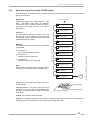
Functional description . . . . . . . . . . . . . . . . . . . . . . . . . . . . . . . . . . . . . . . . . . . . . . . . . . . . . . . . . . . .
Power supply . . . . . . . . . . . . . . . . . . . . . . . . . . . . . . . . . . . . . . . . . . . . . . . . . . . . . . . . . . . . . . . . . . . . .
S&CC supply . . . . . . . . . . . . . . . . . . . . . . . . . . . . . . . . . . . . . . . . . . . . . . . . . . . . . . . . . . . . . . . . . . . . .
CD-PRO supply . . . . . . . . . . . . . . . . . . . . . . . . . . . . . . . . . . . . . . . . . . . . . . . . . . . . . . . . . . . . . . . . . . .
Digital display. . . . . . . . . . . . . . . . . . . . . . . . . . . . . . . . . . . . . . . . . . . . . . . . . . . . . . . . . . . . . . . . . . . . .
Number of plays and cash counter . . . . . . . . . . . . . . . . . . . . . . . . . . . . . . . . . . . . . . . . . . . . . . . . . . . .
Selection and CD carrier . . . . . . . . . . . . . . . . . . . . . . . . . . . . . . . . . . . . . . . . . . . . . . . . . . . . . . . . . . . .
Start / counting process . . . . . . . . . . . . . . . . . . . . . . . . . . . . . . . . . . . . . . . . . . . . . . . . . . . . . . . . . . . . .
CD transfer . . . . . . . . . . . . . . . . . . . . . . . . . . . . . . . . . . . . . . . . . . . . . . . . . . . . . . . . . . . . . . . . . . . . . .
Mute off . . . . . . . . . . . . . . . . . . . . . . . . . . . . . . . . . . . . . . . . . . . . . . . . . . . . . . . . . . . . . . . . . . . . . . . . .
Play . . . . . . . . . . . . . . . . . . . . . . . . . . . . . . . . . . . . . . . . . . . . . . . . . . . . . . . . . . . . . . . . . . . . . . . . . . . .
Cancel . . . . . . . . . . . . . . . . . . . . . . . . . . . . . . . . . . . . . . . . . . . . . . . . . . . . . . . . . . . . . . . . . . . . . . . . . .
CD return . . . . . . . . . . . . . . . . . . . . . . . . . . . . . . . . . . . . . . . . . . . . . . . . . . . . . . . . . . . . . . . . . . . . . . . .
New selection . . . . . . . . . . . . . . . . . . . . . . . . . . . . . . . . . . . . . . . . . . . . . . . . . . . . . . . . . . . . . . . . . . . .
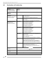
17
Error messages and remedy . . . . . . . . . . . . . . . . . . . . . . . . . . . . . . . . . . . . . . . . 70
17.1
Failures with illumination, display and power system generally . . . . . . . . . . . . . . . . . . . . . . . . . . 71
OMT CD – Edition: 12.05.2005
68
68
68
68
68
69
69
69
69
69
69
69
70
70
3
17.2
Faults with the coin system . . . . . . . . . . . . . . . . . . . . . . . . . . . . . . . . . . . . . . . . . . . . . . . . . . . . . . . . 72
17.3
Faults by selection entry . . . . . . . . . . . . . . . . . . . . . . . . . . . . . . . . . . . . . . . . . . . . . . . . . . . . . . . . . . 73
17.4
Repetitive apply of selected or non-selected CDs to turntable . . . . . . . . . . . . . . . . . . . . . . . . . . . 75
17.5
Failures in the system carrier - gripper arm . . . . . . . . . . . . . . . . . . . . . . . . . . . . . . . . . . . . . . . . . . . 75
17.6
Failures with sound reproduction . . . . . . . . . . . . . . . . . . . . . . . . . . . . . . . . . . . . . . . . . . . . . . . . . . . 77
17.7
CD not properly returned to carrier . . . . . . . . . . . . . . . . . . . . . . . . . . . . . . . . . . . . . . . . . . . . . . . . . . 77
18
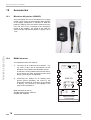
Accessories . . . . . . . . . . . . . . . . . . . . . . . . . . . . . . . . . . . . . . . . . . . . . . . . . . . . . . 78
18.1
Microfone kit (part no. 0006953) . . . . . . . . . . . . . . . . . . . . . . . . . . . . . . . . . . . . . . . . . . . . . . . . . . . . 78
18.2
BGM-Connector . . . . . . . . . . . . . . . . . . . . . . . . . . . . . . . . . . . . . . . . . . . . . . . . . . . . . . . . . . . . . . . . . . 78
19
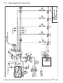
Wiring and connection diagrams . . . . . . . . . . . . . . . . . . . . . . . . . . . . . . . . . . . . . 79
19.1
Wiring diagram door - illumination . . . . . . . . . . . . . . . . . . . . . . . . . . . . . . . . . . . . . . . . . . . . . . . . . . 79
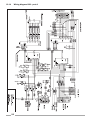
19.2
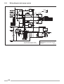
Connection diagram OMT CD . . . . . . . . . . . . . . . . . . . . . . . . . . . . . . . . . . . . . . . . . . . . . . . . . . . . . . 80
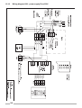
19.3
Board layout Selection & Credit Computer. . . . . . . . . . . . . . . . . . . . . . . . . . . . . . . . . . . . . . . . . . . . 81
19.4
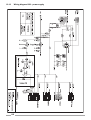
Wiring diagram Selection & Credit Computer . . . . . . . . . . . . . . . . . . . . . . . . . . . . . . . . . . . . . . . . . 82
19.5
Board layout CDM12 SC . . . . . . . . . . . . . . . . . . . . . . . . . . . . . . . . . . . . . . . . . . . . . . . . . . . . . . . . . . . 83
19.6
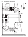
Wiring diagram CDM12 SC . . . . . . . . . . . . . . . . . . . . . . . . . . . . . . . . . . . . . . . . . . . . . . . . . . . . . . . . . 84
19.7
Wiring diagram 24V distributor interface . . . . . . . . . . . . . . . . . . . . . . . . . . . . . . . . . . . . . . . . . . . . . 85
19.8
Wiring diagram motor page system . . . . . . . . . . . . . . . . . . . . . . . . . . . . . . . . . . . . . . . . . . . . . . . . . 86
19.9
Wiring diagram bubble tubes . . . . . . . . . . . . . . . . . . . . . . . . . . . . . . . . . . . . . . . . . . . . . . . . . . . . . . . 87
19.10
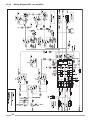
Wiring diagram K99 - power supply . . . . . . . . . . . . . . . . . . . . . . . . . . . . . . . . . . . . . . . . . . . . . . . . . 88
19.11
Wiring diagram K99 - output transformer . . . . . . . . . . . . . . . . . . . . . . . . . . . . . . . . . . . . . . . . . . . . . 89
19.12
Wiring diagram K99 - pre-amplifier . . . . . . . . . . . . . . . . . . . . . . . . . . . . . . . . . . . . . . . . . . . . . . . . . . 90
19.13
Wiring diagram K99 - sound control . . . . . . . . . . . . . . . . . . . . . . . . . . . . . . . . . . . . . . . . . . . . . . . . . 91
19.14
Wiring diagram K99 - port A . . . . . . . . . . . . . . . . . . . . . . . . . . . . . . . . . . . . . . . . . . . . . . . . . . . . . . . . 92
19.15
Wiring diagram K99 - Mute . . . . . . . . . . . . . . . . . . . . . . . . . . . . . . . . . . . . . . . . . . . . . . . . . . . . . . . . 93
19.16
Wiring diagram K99 - power supply Euro 230V . . . . . . . . . . . . . . . . . . . . . . . . . . . . . . . . . . . . . . . . 94
19.17
Wiring diagram K99 - power supply UL/USA 117V. . . . . . . . . . . . . . . . . . . . . . . . . . . . . . . . . . . . . . 95
20
Declaration of Conformity . . . . . . . . . . . . . . . . . . . . . . . . . . . . . . . . . . . . . . . . . . 96
4
OMT CD – Edition: 12.05.2005
1
Unpacking
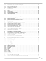
1.1
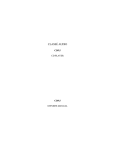
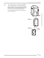
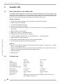
Unlocking
The key is stored in the coin return cup in the
RH cabinet wall. The key WUA 1 unlocks the
cabinet by turning the key clockwise. The lock is
spring loaded, press slightly against the door,
this allows the key to turn easily. The two other
keys with 5 digit number codes unlock the cash
box at the bottom of the RH cabinet wall. In this
box the hand transmitter is located if an infrared
remote control has been installed.
WUA 1
for door
WU
A1A1
456734
WU
1
R
SE
LECT
ION
CSNo
K
.: 00
5974
5
2
4
3
OP
5
TIO
N
6
7
RE
8
SE
T
9
0
-
MUS
IC
PO
+
CA
NC
EL
+
MU
TE
WER
IN
CH TERN
AN
NE
L1
EX
CH TERN
AN
NE
L2
for cash box
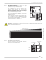
1.2
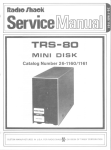
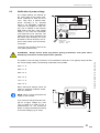
Removal of mechanism shipping guards
1.
The mechanism platform is fixed to cabinet
with one bolt in front LH side (1) and one
bolt back RH side (1). Remove both completely using a 13mm spanner or a large
screw driver. Possibly you can use the tool
fixed to the lid of the gear box (2).
1
2
5
3
7
1
2.
Remove plastic string at the pivot point of
the pressure arm (3).
3.
Remove plastic holder securing CD player
chassis (4).
4.
Remove foam (5), laser cover (6) securing
laser head in CD player and instruction
plate (7).
5.
Remove foam between magnetic pressure
disc and black plastic cover (8).
OMT CD – Edition: 12.05.2005
8
6
4
5
OPERATING INSTRUCTIONS
Unlocking
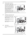
Removal of motor book shipping guards
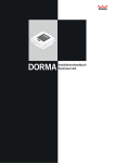
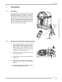
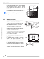
1.3
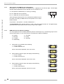
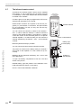
Removal of motor book shipping guards
Cut both plastic strings on both sides of the
book (1).
Press push buttons (2) inside and turn down the
book (3).
Remove elastic band from the motor book systems (4).
OPERATING INSTRUCTIONS
NOTE: Save the removed shipping guards. You
may need them if you decide to move your machine to another location.
1.4
4
1
1
2
2
3
4
3
Power on
NOTE: Make sure that wall socket is grounded
properly.
The CD-jukebox operates on normal household
power outlet. Set mains switch at rear wall of cabinet to on position. If the selection and credit
memory is empty the basket turns once and the
left two digits show alternatly a "0". After a short
time the display counts up to the carrier size in
the two RH digits (50 or 00 for 100 discs). After
this the basket stops in position "01". The digital
display shows "0 0 0 0", then "0 0 0 1" when a
basket with 100 CDs is used "0 1 0 1" for a 50
CD carrier.
6
power switch
o.k. ?
OMT CD – Edition: 12.05.2005
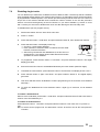
CD handling precautions - CD and player cleaning
2
Loading compact discs
2.1
CD handling precautions - CD and player cleaning
Dust, fingerprints or other dirt on the disc surface can
cause skipping, jumping or sticking problems.
OPERATING INSTRUCTIONS
Because of this never touch the surface of a disc! However it is rather easy to remove nicotine, dust or fingerprints.
Nicotine, dust, fingerprints:
Dust can be removed with a lintfree soft cloth. If necessary, remove heavy dirt or fingerprints with a moistened
soft cloth soaked in a solution of water and a detergent.
Never use record cleaning sprays or anti static sprays!
Furthermore, do not use other types of cleaners containing benzene, thinner or other solvents. These liquids will
cause damage to the surface of discs. Move the cloth
from the inside towards the outside and not in circular
motion.
Removing scratches:
Use a soft cloth and a soft polish.
Laser lens cleaning:
Smoke and dust soils the lens. It can be cleaned with a
cue-tip soaked in a detergent (i.e. Kodak Lens Cleaner,
part no. 0051735). Place the tip on the lens and press
down carefully.
ATTENTION! The whole laser unit is very sensitive!
!
Move the cue-tip only in the direction shown in the picture (perp. to the sledge direction).
!
Do not scratch the special treated surface of the
lense.
!
Take care that the cleaning solution will not run into
the focus unit.
!
Keep away metal parts from the lens unit. A strong magnet is located underneath the lens. It attracts also smallest metal parts and so can block the complete unit.
OMT CD – Edition: 12.05.2005
7
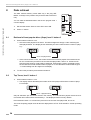
Inserting CDs
2.2
Inserting CDs
OPERATING INSTRUCTIONS
Insert up to 50 or 100 CDs, depending on the
compartments in the carrier. Start with 01. The
"Label" must show always to the left, towards
the next lower number. To achieve the optimum
position for loading, press in steps the lever "rotate carrier". If less than 50 (100) discs are
used, the number of discs used has to be programmed in the service program level 1, button
5 (see chapter "Programming number of CDs in
the carrier", see page 9).
01
ATTENTION! For carriers with 100 CDs the position ’00’ is the 100th CD.
lever
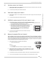
It is recommended to insert the Compact Disc
and then the title page into the appropriate numerical slot position of the motor page system.
The pages can be turned manually by hand without any damage to the motor drive. In some
models the transparent dust cover of the record
carrier has to be lifted up at the front, it will rest
in this position.
NOTE: After unpacking or if you turned the pages manually sometimes it seems that the motorbook does not turn properly. In this case turn
the whole motorbook once forward and backward using the buttons.
It is necessary to reprogramme the number of
CDs in the carrier if a number less than 50 or
100 discs are inserted to avoid the changer mechanism operating with empty compartments.
1 2
3 4
5 6
7 8
9 0
R
If the number of CDs is programmed correctly
the display will flash when you select an empty
compartment. A flashing display always indicates a wrong selection or not enough credit.
The number of CDs in the carrier has to be programmed in service level 1, selection button 5,
described as follows.
8
buttons
to turn the
motor book
OMT CD – Edition: 12.05.2005
Programming number of CDs in the carrier
2.3
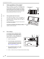
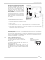
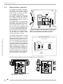
Programming number of CDs in the carrier
At the rear wall inside the jukebox cabinet the Selection &
Credit Computer is situated. Some units are equipped
with a metal cover. In this case the slide switch "SERVICE" and the button "LT" are accessible through holes.
EXTRA EINGANG 300mV
EXTRA INPUT 300mV
R
L
DECKEL ABNEHMEN
REMOVE COVER
0056041
Verstärker K 99
Amplifier K 99 C-UL
MECHANIK
MECHANISM
0058484
MONO
STEREO
BGM
Treble
EINGANG CD
INPUT CD
R
L
Extern
Intern
Channel 1 Channel 2 Bass
SICHERUNG
F1 - F4
FUSE
100-240 V 117 V
50Hz/60Hz 60Hz
3,0 AMP
T4A
250 V AC
SLOW BLOW
ANZEIGE / DISPLAY
MUTE
AVC
RS232
MICRO
12V=
30V~ 26V~ 26V~
DC
AC
AC
AC
RS 232
INFRAROT-REGLER
INFRARED-REMOTE
AUSGANG
MIKROFON
OUTPUT
MICROPHONE
R
L
OPTION
L
R
EXTERNER LAUTSPRECHER
EXTERNAL SPEAKER
8W / 80 W
OPTION
CAUTION
TO REDUCE THE RISK
ONLY
OF FIRE REPLACEAND
WITH SAME TYPE
RATING FUSE
TAPE
BGM
ok.
SCHALTER / SWITCHES
2-KANAL / 2-CHANNEL
1
2
STEREO
1
Set the slide switch ‘service’ at the SCC-unit to ON.
2.
Press ‘LT’ button.
3.
Press selection button 5 -hold down- and press selection button R than release both buttons.
4.
Enter the number of inserted CDs (without BGM
CDs) with two digits followed by 00, example: 50 for
50 discs
(exception: 100. CDs = 00).
F3
F4
BGM
F2
RWEITERUNG
EE
XTENSION
FERNREGLER
REMOTE-CONTROL
BUBBLE-TUBES
DECKEL ABNEHMEN
REMOVE COVER
NETZTRAFO
TRANSFORMER
240 Netzspannung
230
50/60 Hz
220
210 Mains Voltage
50/60 cps
117
100
Achtung!
den Netzstecker
Vor Abnahme der Kappe
ziehen!
Warning!
Shock hazard!
Do not open!
Netzsicherung
Mains Fuse
Schein- T 4A
annehmer 210-240V - F 6A
100-117V
Billacceptor
Sicherungen mit
Zur Beachtung: Nur
gleichem Wert
gleicher Größe und
zu vermeiden.
verwenden, um Schäden
Selection &
Credit Computer
the risk of fire
Caution: To reduce
typ and rating fuses.
replace only with same
CDM 12
CD Tower
Externer Hauptschalter
External Mains switch
Leuchtstofflampen
Fluorescent Lamps
230V / 117V
OPERATING INSTRUCTIONS
1.
F1
CD-TRAFO
CD-TRANSFORMER
Verstärker
Amplifier
To programme the number of inserted CDs (service program, level 1):
2
EIN/ON
AUS/OFF 3 AVC
ANAL/2CHANNEL
STEREO 4 MODE 2-K
CD 5 INPUT TAPE
EIN/ON
AUS/OFF 6 BGM
INTERNER LAUTSPRECHER
INTERNAL SPEAKER
To check the new settings, press selection button 5
again.
Exit the service program:
Set the slide switch ‘service’ at the SCC unit to OFF.
TT
K
2.
Press ‘LT’ button.
ON
BR
Service
OFF
" The changer starts an initialisation run. After this the
GP+6
F
6
5
4
3
2
0
GP
7
6
5
4
3
2
0
BS
6
5
4
3
2
1
0
B4
6
5
4
3
2
1
0
6
5
4
3
2
1
0
B3
B2
M
LT
1
2
4
5
T1
10
20
T
1.
button LT
slide switch
SERVICE
+B
B1
P6
jukebox is ready to operate.
P5
Selection &
Credit Computer
P8
CDM 4I / CDM 12
0040264
OMT CD – Edition: 12.05.2005
ON
Memory
OFF
9
Coin operation and coin return
3
Coin operation or free play?
Both coin operation or free play are adjustible at the
“Selection & Credit Computer” unit. It is located at the
rear wall inside the cabinet underneath the CD-player.
Special jumpers (short wires, located in the accessory
pack of the manual ) are used to be set on the SCCunit. As long as no jumper is set in row GP from 0 to F
(free play) the jukebox works with coins only.
jumper from 0 to F
in row GP
TT
F
6
5
4
3
2
0
GP
BR
GP+6
6
5
4
3
2
1
0
B4
B3
6
5
4
3
2
1
0
B2
6
5
4
3
2
1
0
M
LT
B1
Coin operation and coin return
1
From factory the jukebox is set to coin operation. If
you insert a certain number of coins according to the
denomination label, the jukebox gives the credits or
plays it is adjusted for.
2
3
5
4
6
7 8
9
0
R
You will get your change by turning the rotary switch at
the RH side of the jukebox.
2 Spie
le 1,DM
5 Spie
le 2,DM
14 Spie
le 5,DM
If you want to change the play prices you have to denomination
change the jumper settings on the SCC-unit. See exlabel
amples in the accessory pack.
3.2
Price settings
In the ’EURO’ version no play prices are preset. Usually the prices are preset by the factory according to the denomination label in
the accessories. If other combinations are
required, refer to the following examples. For
price setting proceed as follows:
3
TT
K
1.
2.
10
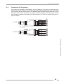
Switch on the jukebox.
Coin output plugs (1) should be set according an separate attached instruction
by connecting to the pin row (2) on the
SCC unit. Pay attention to wiring colors
(refer to chapt. 3.4 on page 11).
ON
Service
OFF
BR
GP+6
F
6
5
4
3
2
0
GP
7
6
5
4
3
2
0
BS
B4
6
5
4
3
2
1
0
2
4
B3
6
5
4
3
2
1
0
B2
6
5
4
3
2
1
0
M
B1
LT
1
1
2
4
5
T1
10
20
T
OPERATING INSTRUCTIONS
3.1
7
6
5
4
3
2
0
BS
button LT
+B
P6
P5
Selection &
Credit Computer
P8
CDM 4I / CDM 12
3.
Set the attached jumpers in B1 to B4
according to the number of the desired
additional bonus plays. (3).
4.
Press „LT“ button once (4) to accept the new price/bonus setting.
0040264
ON
Memory
OFF
OMT CD – Edition: 12.05.2005
Examples
Examples
2$
USA
1 play 50 cts
25cts
$ 1.00
3 plays $ 1.00
21 plays $ 5.00
$ 1.00
GB
1 play 30 p
10p
20p
2 plays 50 p
5 plays £ 1
50p
6
5
4
3
2
1
0
B1
F
6
5
4
3
2
0
GP + 6 GP
7
6
5
4
3
2
0
BS
6
5
4
3
2
1
0
B4
6
5
4
3
2
1
0
B3
6
5
4
3
2
1
0
B2
6
5
4
3
2
1
0
B1
F
6
5
4
3
2
0
GP + 6 GP
7
6
5
4
3
2
0
BS
6
5
4
3
2
1
0
B4
6
5
4
3
2
1
0
B3
6
5
4
3
2
1
0
B2
6
5
4
3
2
1
0
B1
T.T.
+2
+3
BR
T.T.
+2
+3
BR
M
LT
AUS
1
2
4
5
T1
10
20
10ct
20ct
50ct
3 plays 2 $
+B
1$
M
LT
2$
USA
1
2
4
5
T1
10
20
25cts
$ 1.00
3 plays $ 1.00
18 plays $ 5.00
$ 1.00
M
LT
1
2
4
5
T1
10
20
Free Play
+B
7
6
5
4
3
2
0
BS
6
5
4
3
2
1
0
B4
6
5
4
3
2
1
0
B3
6
5
4
3
2
1
0
B2
6
5
4
3
2
1
0
B1
F
6
5
4
3
2
0
GP + 6 GP
7
6
5
4
3
2
0
BS
6
5
4
3
2
1
0
B4
6
5
4
3
2
1
0
B3
6
5
4
3
2
1
0
B2
6
5
4
3
2
1
0
B1
F
6
5
4
3
2
0
GP + 6 GP
7
6
5
4
3
2
0
BS
6
5
4
3
2
1
0
B4 B3
6
5
4
3
2
1
0
B2
6
5
4
3
2
1
0
B1
T.T.
+2
+3
BR
1 play 50 cts
+B
F
6
5
4
3
2
0
GP + 6 GP
T.T.
+2
+3
BR
1 play 1 $
T.T.
+2
+3
BR
M
LT
mechanical coin validator
USA
1
2
0.25 blue
M
LT
4
5
1$ grey
T1
10
20
LT
T
SCC
+B
4
5
1$ orange
yellow
LT
white
brown
1
2
SCC
T1
10
20
M
LT
10ct blue
20ct red
50ct orange
violet
1$ yellow
2$ green
brown
DIP switches
on interface
off - on
mechanical
coin validator
111
1
10 ct
20 ct
50 ct
1$
2$
2
3
4
5
6
GB
1
2
4
5
SCC
T
LT
T1
10
20
+B
10p yellow
20p orange
2.00 weiß
electronical coin validator
EURO
4
5
grey
50p red
1£ brown
green
violet
LT
SCC
Interface
T1
10
20
grey
green
violet
+B
NRI
Credit
OMT CD – Edition: 12.05.2005
0.50 red
1.00 brown
2.00 white
Interface
NRI
G13
1
2
T
electronical coin validator
1
2
4
5
T1
10
20
+B
+B
Cashflow
1
2
4
5
T1
10
20
+B
electronical coin validator
AUS
1
2
4
5
T1
10
20
+B
Color codes of coin input
T
3.4
1£
6
5
4
3
2
1
0
B2
Credit
G13
11
OPERATING INSTRUCTIONS
5 plays 2 $
6
5
4
3
2
1
0
B3
T
1$
50ct
6
5
4
3
2
1
0
B4
T
20ct
7
6
5
4
3
2
0
BS
T
10ct
F
6
5
4
3
2
0
GP + 6 GP
T.T.
+2
+3
BR
T
2 plays 1 $
T
AUS
T
3.3
Free play
3.5
Free play
To set the jukebox to free play:
1.
OPERATING INSTRUCTIONS
3.6
In case there are already jumpers in the rows GP
and BS, notice their position (for later resetting to
coin operation) and remove them.
row BS
TT
F
BR
GP+6
6
5
4
3
2
0
GP
button LT
7
6
5
4
3
2
0
BS
B4
6
5
4
3
2
1
0
B3
6
5
4
3
2
1
0
B2
6
5
4
3
2
1
0
M
LT
B1
2.
Set a jumper from 0 to F (free play) in the row GP on the SCC unit.
3.
Press ‘LT’ button.
4.
Now one track is selectable without coin insertion.
5.
In between two to six plays are selectable by setting an additional jumper in the row ‘BS’ (Bonus
Step) from 0 to 2 or from 0 to 6.
6.
Up to 47 tracks are pre-selectable by setting a jumper in the row ‘BS' from 0 to 7.
Test credit
For repair and test purposes it is possible to give test credits.
By touching the test credit button you get one credit also
shown in the digital display. You can terminate un-used credits by pressing the LT button.
In jukeboxes with an electronical coin validator you can find
the test credit button on the coin validator interface board.
In jukeboxes with mechanical coin validator the test credit
button is mounted over the return lever inside.
12
OMT CD – Edition: 12.05.2005
OMT CD – Edition: 12.05.2005
total plays
plays
B1...B4
from bonus
step
plays from
GP:
inserted
money
pulse
1.
2.
3.
4.
5.
6.
7.
8.
9.
10.
11.
12.
1
2
4
5
T1
10
20
13.
+B
T
Price settings:
15.
16.
17.
18.
19.
20.
21.
OPERATING INSTRUCTIONS
14.
+35 V !
...............
GND
...............
...............
...............
test credit
...............
...............
...............
...............
...............
22.
23.
24.
25.
Test credit
13
How to select a track
4
Track selection
4.1
How to select a track
If credit exists or free play is set you can select tracks by means of the buttons 0 - 9 on the keyboard.
First enter the number of the CD with two digits, then the track with two digits too. Example: CD 2,
track 9: Enter 0 - 2 - 0 - 9 (Exception: CD 100 = 00.)
OPERATING INSTRUCTIONS
4.2
The button R
You can delete wrongly entered numbers up to the
third digit by means of the button R (Reset). But after
having entered the fourth digit the jukebox stores and
executes a selection. By pressing the button R the
available credit will be displayed for a few seconds.
button R
4.3
The display flashes
After entering the fourth digit of a selection the jukebox starts to search
and play the selected CD immediately. If the display flashes the entered
selection was not valid. Check:
!
if credit is available or
!
if the selection is higher then the programmed number of CDs in the carrier
If you select a higher track number than available on a CD the jukebox overcounts the tracks and
starts at the beginning.
Example: CD 03 contains 17 tracks. But selected track is 0 - 3 - 1 - 9. The jukebox plays track 02 of
CD 03.
A maximum of 25 tracks per CD can be selected!
14
OMT CD – Edition: 12.05.2005
I do not like this track - the button CANCEL
4.4
I do not like this track - the button CANCEL
If you do not like a track you can cancel it by pressing
the button 'CANCEL' at the rear side of the jukebox or at
the remote control. The jukebox stops playing or plays
the next track if a selection has already been made.
control
terminal F91
0058407
MIN
VOLUME
BASSINTERN
CHANNEL 1
TREBLE
BALANCE
MAX
+
-
MUTE
MODE
CANCEL
MIN
control
terminal K99
OMT CD – Edition: 12.05.2005
OPERATING INSTRUCTIONS
You can terminate all selections only by pressing the button LT on the SCC unit .
PRESET
CANCEL
EMUTE
XTERN
CHANNEL 2
MAX
button
CANCEL
MIN
MAX
MUTE
CANCEL
MIN
MAX
15
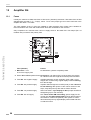
Volume, sound and balance control - amplifier K99
5.1
Volume, sound and balance control - amplifier K99
Volume control
You can control the volume of the jukebox from different
points at the same time:
DECKEL ABNEHMEN
REMOVE COVER
EXTRA EINGANG 300mV
EXTRA INPUT 300mV
L
R
Volume, sound and balance control
Verstärker K 99
Amplifier K 99 C-UL
MECHANIK
MECHANISM
T4A
Extern
Channel 1 Channel 2 Bass
Treble
BGM
EINGANG CD
INPUT CD
L
R
100-240V 117 V
50Hz/60Hz 60Hz
Intern
ANZEIGE / DISPLAY
3,0 AMP
250 V AC
SLOW BLOW
30V~ 26V~ 26V~ 12V=
DC
AC
AC
AC
2-KANAL / 2-CHANNEL
MUTE
AVC
RS232
MICRO
BGM
ok.
SCHALTER / SWITCHES
AUTO 1 MUTE
NORMAL 2 RS232
STEREO
TAPE
RS 232
OPTION
STEREO
CAUTION
TO REDUCETHE RISK
OF FIRE REPLACE ONLY
WITH SAMETYPE AND
RATING FUSE
SICHERUNG
F1 - F4
FUSE
INFRAROT-REGLER
INFRARED-REMOTE
AUSGANG
OUTPUT
L
R
With an optional connectable IR remote control.
R
L
EXTERNER LAUTSPRECHER
EXTERNAL SPEAKER
8W / 80 W
OPERATING INSTRUCTIONS
2.
With the pots Vol.1 and Vol.2 on the amplifier.
OPTION
MONO
1.
AUS/OFF
SERVICE
SEPARATE 1 VOLUME PARALLEL
With the pots of the control box at the rear side of the
jukebox.
CD-TRAFO
CD-TRANSFORMER
F1
F3
F2
F4
HIGH 2 AVC
AUS/OFF 3 AVC
STEREO 4 MODE
CD 5 INPUT
AUS/OFF 6 BGM
LOW
EIN/ON
2-KANAL/2CHANNEL
TAPE
EIN/ON
ERWEITERUNG
EXTENSION
BUBBLE-TUBES
NETZTRAFO
TRANSFORMER
BGM
3.
INTERNER LAUTSPRECHER
INTERNAL SPEAKER
MIKROFON
MICROPHONE
5
FERNREGLER
REMOTE-CONTROL
DECKEL ABNEHMEN
REMOVE COVER
The device from which the volume is altered last determines
it.
The volume control unit can be taken out and may be mounted at another place as a remote control.
Its cable may be extended as required with any kind of wire. The voltages of the control wires are 5V
DC.
The control box has two volume knobs (Intern / Channel 1 and Extern / Channel 2). In position ”Stereo” the knob “Intern / Channel 1” is effective for the internal speakers. The knob Extern / Channel 2
is controlling the volume of the RCA outputs for an optional external amplifier. In position ”2 Channel”
of the DIP switch the channels1 (RH) and 2 (LH) are controllable separately.
The pots Vol. 1 and Vol. 2 on the amplifier are not effective if the wire control box is connected
16
OMT CD – Edition: 12.05.2005
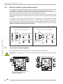
Volume, sound and balance control - amplifier K99
The infrared remote control
As desired an infrared remote control will be installed
from factory or can be delivered as conversion kit (part
no. 0058809). If it has been installed the hand transmitter is located in the cashbox.
RCS-K
If credit is given or free play is programmed a CD can
be selected with the buttons 0 to 9 and R.
Double button functions as required in the service programs (i.e. press button 5 -hold down- and press button R), are impossible. For this you only can use the
keyboard of the jukebox.
You can control the volume by means of the buttons +
and -. In stereo mode the internal +/- buttons control
the volume of the internal speakers. The external +/buttons control the volume of the K99 RCA jacks for
an optional external amplifier. In 2-channel mode you
can control the external speakers by the buttons + and
- of the external channel.
No.: 0059745
SELECTION
selection
buttons
1
2
3
OPTION
4
5
6
RESET
7
8
9
0
POWER
VOLUME
music control
buttons
-
+
-
+
INTERN
CHANNEL 1
EXTERN
CHANNEL 2
CANCEL MUTE
Beam the jukebox directly if possible.
You can connect the wire remote control box as well.
battery type
LR03 (AAA)
The power-on volume level is always set by the channel 1 and 2 pots on the amplifier or on the control box
(if connected).
Batteries will be delivered. To open the battery compartment move the cover like shown in the picture.
Needed battery type and position of the batteries in
the hand transmitter are shown on the casing.
BATTERY:
IEC LR03
(AAA)
+
+
+
+
position
of batteries
Part no. of the hand transmitter: 0059745.
OMT CD – Edition: 12.05.2005
17
OPERATING INSTRUCTIONS
5.1.1
Volume, sound and balance control - amplifier F91
5.2
Volume, sound and balance control - amplifier F91
The control terminal at the rear
With the control terminal at the rear side of the jukebox
the volume, treble, bass and balance can be controlled
individually.
OPERATING INSTRUCTIONS
After power up or if no button has been pressed for approx. 5 sec or after the button PRESET has been
pressed, the terminal stays in the mode "VOLUME".
The LED "VOLUME" lights. In this mode you can control the volume by means of the buttons '+' and '-'.
One LED corresponds to each mode. All modes are
accessible by pressing the ‘mode’ button. With the buttons '+' and '-' treble, bass or balance can be controlled.
current
mode
VOLUME
BASS
TREBLE
BALANCE
+
-
PRESET
MODE
CANCEL
MUTE
0039661
The control terminal can be taken out and be used as
a wired remote control.
ATTENTION! Depending on adjusted volume of the
jukebox noise levels of more than 70 dB can be reached.
+/- VOLUME
The meanings of the buttons...
!
!
!
!
18
MODE: Switches to the next operating mode. After
about 5 seconds without operating any buttons, ‘volume’ mode is resumed.
PRESET: Volume, bass, treble, and balance are
set to the pre-set according to DIP switch setting.
Actual mode is set to ‘Volume’.
CANCEL: Rejects a playing track. If album play is
selected the next track will be played.
LED Volume
lights
Press button MODE
+/- BASS
LED Bass
lights
Press button MODE
+/- TREBLE
LED Treble
lights
Press button MODE
+/- BALANCE
LED Balance
lights
Press button MODE
MUTE: As long as this button is activated, the amplifier output is muted.
OMT CD – Edition: 12.05.2005
Volume, sound and balance control - amplifier F91
5.2.1
The infrared remote control
As desired an infrared remote control will be installed
from factory or can be delivered as conversion kit (part
no. 0040435). If it has been installed the hand transmitter is located in the cashbox.
RCS
ART.NR.: 0040443
If credit is given or free play is programmed a CD can
be selected with the buttons 0 to 9 and R.
The meanings of the music control buttons are according to the buttons on the control terminal on the rear
side of the jukebox (ref. to the prev. chapter).
selection
buttons
1
2
3
4
5
6
7
8
9
RESET
0
MUSIC
music control
buttons
-
+
MODE
PRESET
+/- VOLUME
MODE
+/- BASS
MODE
CANCEL
MUTE
+/- TREBLE
MODE
+/- BALANCE
MODE
The receiver eye of the infrared remote control is located behind the hole between the design elements on
top of the front door. Beam this point directly if possible.
The common control terminal can be connected besides. It can be mounted outside to display the actual
mode.
battery type
LR03 (AAA)
BATTERY:
IEC LR03
(AAA)
+
+
+
Batteries will be delivered. To open the battery compartment move the cover as shown in the picture.
+
The required battery type and position of the batteries
in the hand transmitter are shown on the casing.
Part no. of the hand transmitter: 0040443.
OMT CD – Edition: 12.05.2005
position
of batteries
19
OPERATING INSTRUCTIONS
Double button functions as required in the service programs (i.e. press button 5 -hold down- and press button R), are impossible. For this you can use the
keyboard of the jukebox only.
SELECTION
Pre-settings for volume
5.3
Pre-settings for volume
Tone
4
2
1
4
2
1
Treble
OPERATING INSTRUCTIONS
After power on of the jukebox or after pressing the button ‘preset’ the values of volume, bass and treble reach the values set by the DIP switches.
You can set the basic values for volume in 63 steps
from zero up to maximum volume.
At the amplifier front side, opening “Volume”, there
are 6 DIP-switches for each channel. These switches
have different values (1, 2 ... to 32). If you add all the
values of the switches in position “ON” you will get the
value for the set volume.
Consequently the switches 32 and 16 give a coarse
adjustment whilst the lower numbers may be used for
fine adjustment.
You can find the recommended settings on the amplifier cover.
Bass
P10
Remote
off
Low Level
L
Clipping
Amplifier F91
0039155
Pre-settings for bass and treble
Similarly the values for bass and treble can be set. Both
channels should be adjusted the same.
Three DIP-switches with the values 1, 2, 4 are provided for
each bass and treble. You can choose 7 different steps from
minimum to maximum. Adding all switches set to "ON" gets
the set value.
The recommended factory settings are printed on the amplifier cover.
If you change the DIP-switch settings while the jukebox
operates remember that the new settings will only take
effect after having pressed the button ‘PRESET’ at the
control terminal.
20
R
Input Tape
L
P10
Remote
Mode
Tape
CD
2-Kanal
Stereo
Mic.-Kit
Input
Volume
32
16
8
4
2
1
32
16
8
4
2
1
R
P4
BGM
L
off
R
R
BGM Level
L
R
L
Line Out
L
on
Verstärker-Sicherungen / Amplifier Fuses
100V - 117V
210V - 240V
Si 1/Si 301 Si 102/Si 103 Si 1/Si 301
Si 2/Si 302 Si 100/Si 101 Si 2/Si 302
T 5A
T 3,15A
MT 4A
Si 102/Si 103
Si 100/Si 101
T 3A
240
230
220
210
117
100
Netzspannung
50/60 Hz
Mains Voltage
50/60 cps
Zur Beachtung Nur Sicherungen mit gleicher Größe und
gleichem Wert verwenden um Schäden zu vermeiden.
Caution: To reduce the risk of fire replace only with
same type and rating fuses.
Achtung!
Vor Abnahme der Kappe den Netzstecker
ziehen!
Attention!
Pull power plug before opening protective
lid!
NOTE: If all switches are in position OFF no volume, if
all switches are in position ON, the maximum volume
appears at power on !
5.3.1
R
Input CD
R
L
on
DIP switch
Leuchtstofflampen/
Flourescent Lamps
230V / 117V
32
16
8
4
2
1
32
16
8
4
2
1
recommended
settings
4
2
1
4
2
1
OMT CD – Edition: 12.05.2005
Pre-settings for volume
6
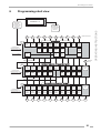
Programming short view
JUKEBOX o.k.
Slide switch
SERVICE
in position ON
and press
button LT
1
0
1
2
3
4
display of
flops
display of
TOP
discs
display of
cash box
contents
display of
total
number
of plays
Display
test,
display of
print out
statistics
Memory
reset
Access
to
Service
level 2
7
8
9
display of
no. of CDs,
Playstimulator
display of
defective
CDs
Moves
the
gripper
arm
Turns
the
CD carrier
display of
identification
number
Programming in
4 digits
Daten
löschen
Programming in
8 digits
CD
STOP
CD
PLAY
CD
PLAY
+
PREVIOUS
EPROM
version
CD
PLAY
+
NEXT
Press and hold
selection button 0...9
and press button R
Selection
button
R
step to service level 2
2
Selection buttons
Statistics
Press and hold
selection button 0...9
and press button R
CD is on turntable
6
5
Clock, Bonus, Playstimulator
display of
time
HH:MM
display of
date
TT:MM
display of
year,
weekday
display of
tracks
per CD
display of
disabled
tracks
CD:TT
Programming in
4 digits
Programming in
4 digits
Programming in
4 digits
Programming in
2 digits
Programming in
4 digits
display of
BGM
times
Access
to
Service
level 3
display of
Happy
Hourtime
display of
Happy
Hour
prices
display of
Playstimulator
time
Option:
reset
memory,
Albumplay
Programming in
4 digits
Programming in
4 digits
Programming in
8 digits
Programming in
2 digits
back to
Service
level 1
step to service level 3
3
Press and hold
selection button 0...9
and press button R
BackGround Music, BGM
Wednesday
display of
BGM
times
Thursday
display of
BGM
times
Friday
display of
BGM
times
Saturday
display of
number of
BGM CDs
BGM
periods
display of
BGM start,
selection
with coins
yes/no
display of
712
no
function
Programming in
16 digits
Programming in
16 digits
Programming in
16 digits
Programming in
16 digits
Programming in
16 digits
Programming in
16 digits
Programming in
4 digits
no
function
free for
future
2
3
4
5
6
7
8
9
display of
BGM
times
Sunday
display of
BGM
times
Monday
display of
BGM
times
Tuesday
Programming in
16 digits
Programming in
16 digits
0
1
OMT CD – Edition: 12.05.2005
back to
Service
level 1
R
21
OPERATING INSTRUCTIONS
Slide switch
SERVICE
in position OFF
and press
button LT
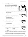
Call up service programs
7
Jukebox programming
Additional features like Playstimulator, BGM time and Happy Hour time are programmable. These
features are programmable in the service mode of the SCC unit.
Call up service programs
OPERATING INSTRUCTIONS
NOTE: To keep the data stored when power is off the plug “Memory” must be set
to “ON” position on the SCC unit, otherwise all programmed data in service levels are reset when power is interrupted.
2. Press button LT
1. Service in
position ON
TT
K
Call up service programs:
ON
Service
OFF
BR
GP+6
F
6
5
4
3
2
0
GP
7
6
5
4
3
2
0
BS
B4
6
5
4
3
2
1
0
B3
6
5
4
3
2
1
0
B2
6
5
4
3
2
1
0
M
B1
LT
1
2
4
5
T1
10
20
T
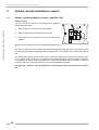
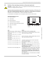
7.1
+B
P6
1.
2.
3.
Set slide switch “Service” from position OFF to ON, then press the LT
button. Service level 1 is reached,
display shows ’0 0’.
P8
CDM 4I / CDM 12
0040264
Press button 4 - hold it - and press
button R, display is dark, service level 2 is reached.
Statistics
2.
Set the slide switch SERVICE in position off.
Memory
in position
ON
Display:
Press button 4 - hold it and press button R
Button R
Service level 2
Clock, Bonus,
Playstimulator
Display:
How to leave service programs
1.
ON
Memory
OFF
Service level 1
Press button 5, display is dark, service level 3 is reached.
NOTE: If button R is pressed first in service levels 2 or 3, the S&CC will jump
back to service level 1 automatically.
7.2
P5
Selection &
Credit Computer
Press button 5
Button R
Press button LT.
Service level 3
BackGround
Music (BGM)
Display:
" The
changer starts an initialisation
run. After this the jukebox is ready to operate.
22
OMT CD – Edition: 12.05.2005
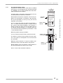
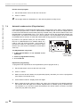
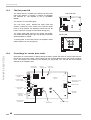
Programming of time functions
Programming of time functions
Service level 2
It is necessary to program the time, date and weekday
once or at least to control these settings. Only then the
jukebox can switch on and off the playstimulator or the
Back Ground Music at the desired time. It is useful to
program time, date and weekday in a single pass.
slide switch
service
Z
K
SERVICE
ON
OFF
F
6
5
4
3
2
0
GP + 6 GP
T.T.
+2
+3
BR
7
6
5
4
3
2
0
BS
LT button
6
5
4
3
2
1
0
B4 B3
6
5
4
3
2
1
0
B2
6
5
4
3
2
1
0
B1
M
1
2
4
5
T1
10
20
LT
T
7.3
+B
To program the time (and also the date):
P6 16
MEMORY - Stecker von OFF
auf ON umstecken, wenn
Top tunes, Popularitätszähler
oder Kassenzähler arbeiten soll.
1.
Set the slide switch ‘service’ at the SCC-unit to ON.
Selection &
Credit Computer
P5 15
CDM 12
7.3.1
7.3.2
to ON if Top tunes, Pop Meter or
Cash Box Content Registration
is required.
1
P8 8
ATTENTION: Placer la prise MEMORY en
position ON, de la position OFF
si le Top Tunes, le compteur de
popularité et la contenu de la
caisse sont demandés.
ON
Memory
OFF
0040264
2.
Press ‘LT’ button.
3.
Press selection button 4 -hold down- and press selection button R than release both buttons.
4.
Service level 2 is reached.
Clock setting, level 2 button 0
5.
Press selection button 0. The display shows the current time.
If the displayed time is not correct:
6.
Press selection button 0 -hold down- and press selection button R. Release both buttons.
7.
Enter the correct time with four digits.
Example:
hours
minutes
Set date, level 2 button 1
8.
Press selection button 1. The display shows the current date.
If the displayed date is not correct:
9.
Press selection button 1 -hold down- and press selection button R. Release both buttons.
Example:
day
month
10. Enter the correct date with four digits.
7.3.3
Set year and weekday, level 2 button 2
11. To display the year and the weekday press selection button 2:
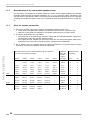
The weekdays are assigned to numbers as shown.
0 = Sunday
4 = Thursday
1 = Monday
5 = Friday
2 = Tuesday
6 = Saturday
3 = Wednesday
Example:
year
weekday
12. To program press selection button 2 -hold down- and press selection button R. Release both
buttons.
13. Enter the correct year with two digits, then enter a 0 followed by the number of the weekday.
OMT CD – Edition: 12.05.2005
23
OPERATING INSTRUCTIONS
ACHTUNG:
ATTENTION: Move MEMORY Plug from OFF
Automatic random select (Playstimulator)
Exit the service program:
1.
Set the slide switch ‘service’ at the SCC unit to OFF.
2.
Press ‘LT’ button.
" The changer starts an initialisation run. After this the jukebox is ready to use.
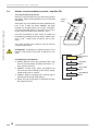
Automatic random select (Playstimulator)
If the Playstimulator is programmed the jukebox plays random tracks of the CDs in carrier registered
in the service program level 1, button 5. CDs declared as BGM CDs (ref. to the next chapter) will not
be used! The time between the last track played by inserted money and the first random track of the
Playstimulator is programmable from 1 up to 98 min. This time is also the repeat time between two
random plays. The volume is the same as in normal operation. The Playstimulator will be interrupted
immediately when a selection is made and restarts after having played the selected track(s).
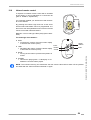
By means of an optional switch you can also switch
the box to CONTINUOUS PLAY MODE without any
need to enter the service program. Part number of
this switch is 0034410. It has to be connected to P8 of
the SCC unit. (This switch is standard for all One More
Time CD).
TT
K
ON
Service
OFF
BR
GP+6
7
6
5
4
3
2
0
BS
F
6
5
4
3
2
0
GP
B4
6
5
4
3
2
1
0
B3
6
5
4
3
2
1
0
B2
6
5
4
3
2
1
0
M
LT
1
2
4
5
T1
10
20
T
OPERATING INSTRUCTIONS
7.4
+B
B1
Continuous
P6
on
Play
off
P5
Selection &
Credit Computer
P8
CDM 4I / CDM 12
0040264
The Playstimulator only works:
!
if Back Ground Music is not activated at the
same time
!
if time is programmed correctly
!
iif no credit left
ON
Memory
OFF
CONTINUOUS
PLAY switch
Repeat time programming
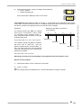
To programme the repeat time for the Playstimulator (service program level 1):
24
1.
Set the slide switch ‘service’ at the SCC-unit to ON.
2.
Press ‘LT’ button.
3.
Make sure that all time details are programmed properly otherwise you have to reprogramme
(see chapter 'The internal clock')
4.
Press selection button 5. Display shows four digits.
5.
Both LH digits show the number of CDs in the carrier, this number has to be indentical with the
real number. Both RH digits show whether Playstimulator is enabled (01-99) or disabled (00).
The numbers 01 up to 98 show repeat time between two random tracks in minutes, 99 means
continuous play without any break.
OMT CD – Edition: 12.05.2005
Automatic random select (Playstimulator)
A = number of CDs in the carrier (00 = 100)
Example:
B = repeat time programmed to 10 minutes
A = 50 CDs in carrier
A
B
A
B
A
B
Example:
A = 63 CDs in carrier
Example:
B = Playstimulator on, continuousplay
7.4.1
6.
Note the number of CDs in carrier.
7.
Press selection button 5 -hold it- and press selection button R.
Display goes dark. Enter the noted number of CDs in carrier and Playstimulator interval time (or
'00' for Playstimulator OFF or '99' for continuous play) with four digits.
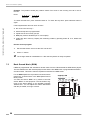
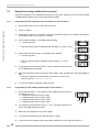
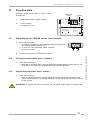
Programming start and stop time
If start and stop time is programmed the jukebox only plays random tracks in this time period.
You can not programme the Playstimulator over 24.00 o’clock (e.g. 23.00 to 2.00 o'clock) !
Call up service program 2 by pressing the slide switch on SCC unit to position ON, press button LT,
then press button 4 -hold it- and press selection button R. Then
press selection button 8. The display shows at first a flashing ’1’.
This means ’start time’.
Then the time will be displayed, here 14.05 o’clock (2.05 p.m.).
Press selection button 8 once again. Now the display shows a flashing ’2’.
This means ’stop time’.
Then the time will be displayed, here 18.30 o’clock (6.30 p.m.).
To reprogramme press selection button 8 - hold - and press selection button R. Release both buttons. The digital display goes dark. Enter the start and stop time with eight digits.
OMT CD – Edition: 12.05.2005
25
OPERATING INSTRUCTIONS
B = no random plays
Back Ground Music (BGM)
Example: The jukebox should play random tracks from 09.00 in the morning to17.00 in the afternoon..
Enter:
0-9-0-0- 1-7-0-0
start time
stop time
To check the start time: press selection button 8. To check the stop time: press selection button 8
again.
If the Playstimulator does not work. Check if:
OPERATING INSTRUCTIONS
!
the clock is set correctly ?
!
start and stop time is programmed?
!
repeat time is set correctly (not 0)?
!
BGM play mode is disabled (ref. to next chapter).
!
credits are still in memory. Display the remaining credits by pressing button R. If so, delete with
button LT.
Exit the service program:
1.
Set the slide switch ‘service’ at the SCC unit to OFF.
2.
Press ‘LT’ button.
" The changer starts an initialisation run. After this the jukebox is ready to operate.
7.5
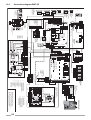
Back Ground Music (BGM)
If BGM is programmed and activated a random track from the CDs declared for BGM will be played.
The time between the last selected played track and the first BGM track is programmable between 1
and 98 minutes. This time is also the repeat time between two BGM tracks.
amplifier K99
Intern
Extern
Channel 1 Channel 2 Bass
Treble
BGM
ANZEIGE / DISPLAY
MUTE
TAPE
RS 232
AVC
RS232
MICRO
BGM
ok.
SCHALTER / SWITCHES
AUTO 1 MUTE
NORMAL 2 RS232
INFRAROT-REGLER
INFRARED-REMOTE
For the K99 amplifier the reproduction loudness will be
reduced by a certain factor in the BGM (Back Ground
Music) mode.
You also can switch “BGM” on by means of the DIP
switch “BGM” for test purposes. The RH bottom segment of the status display on the amplifier indicates
“BGM active”. You can adjust the volume attenuation
with the pot “BGM”, as long it is active.
AUS/OFF
SERVICE
SEPARATE 1 VOLUME PARALLEL
HIGH
AUS/OFF
STEREO
CD
2
3
4
5
AVC
AVC
MODE
INPUT
AUS/OFF 6 BGM
LOW
EIN/ON
2-KANAL/2CHANNEL
TAPE
EIN/ON
ERWEITERUNG
EXTENSION
26
FERNREGLER
REMOTE-CONTROL
OMT CD – Edition: 12.05.2005
Back Ground Music (BGM)
F91: The volume for BGM reproduction is reduced compared to the normal volume. It is adjustable with the two BGM pots (RH channel / LH
channel) on the amplifier. BGM mode is active
when the LED on the amplifiers lights. The
source of the BGM control signal is the SCC
unit plug brown (X6), pin 1. Once the BGM
mode is activated, it is not possible to operate
the Playstimulator.
amplifier F91
Tone
4
2
1
4
2
1
Treble
Bass
P10
off
Low Level
L
L
on
Remote
R
Input CD
R
Clipping
Amplifier F91
0039155
R
Input Tape
L
P10
Remote
Stereo
CD
Mode
2-Kanal
Tape
Mic.-Kit
Input
Volume
P4
BGM
L
off
R
L
R
BGM Level
L
R
Line Out
L
on
BGM light emitting
diode (yellow),
indicates whether
BGM is active
BGM trim pots
1.
Set the slide switch ‘service’ at the SCC-unit to ON.
2.
Press ‘LT’ button.
3.
Press selection button 4 -hold down- and press selection button R then release both buttons.
4.
Press selection button 5. Service level 3 is reached. The display is dark. At this level all BGM
options can be checked and/or programmed.
For the K99 amplifier the reproduction loudness will be reduced by a certain factor in the BGM (Back
Ground Music) mode.
You also can switch “BGM” on by means of the DIP switch “BGM” for test purposes. The RH bottom
segment of the status display on the amplifier indicates “BGM active”. You can adjust the volume attenuation with the pot “BGM”, as long it is active.
7.5.1
Number of BGM CDs and repeat time
Press selection button 7, the display shows e.g.:
A = number of BGM CDs; disabled for Playstimulator
BGM OFF = 00.
Example:
5 CDs reserved for BGM,
repeat time 10 min.
B = Repeat time between the single BGM tracks (10 min.)
BGM-continuous play = 00
To programme press selection button 7 -hold down- and
press selection button R. Release both buttons. The display
goes dark. Enter the number of CDs and the repeat time with
4 digits.
OMT CD – Edition: 12.05.2005
A
B
27
OPERATING INSTRUCTIONS
R
If a selection is made by means of coin insertion
the track being played will be interrupted immediately. Two intervals can be programmed for
each weekday.
To enable BGM (service program, level 3) :
32
16
8
4
2
1
32
16
8
4
2
1
Back Ground Music (BGM)
7.5.2
Start position for BGM CDs and configuration
Press button 8. The start position of the BGM CDs is displayed in the left two digits. The RH digits
indicate whether BGM CDs can be selected over coin insertion or not.
A = start position of BGM CDs (01 = factory pre-setting)
B = 00 - BGM CDs can be selected
B = 01 - BGM CDs can NOT be selected
OPERATING INSTRUCTIONS
After entering this data the SCC unit calculates the BGM end position itself. For loading of BGM discs the end position can be calculated as follows:
A
B
end position = start position + number of BGM CDs - 1
To reprogramme press selection button 8 - hold - and press selection button R. The digital display
goes dark. Enter start position and the selection option with 4 digits!
7.5.3
BGM time zones at different weekdays
You can programme each weekday differently with two intervals per day. The following steps are the
same for the buttons 1 to 6 in service level 3 according to the table for weekdays..
0 = Sunday
1 = Monday
2 = Tuesday
3 = Wednesday
1.
4 = Thursday
5 = Friday
6 = Saturday
Press button 0, the display shows flashing:
# 0 (LH) = Sunday
# 1 means start time one,
then the time will be displayed, here 9.00 o’clock.
2.
Press selection button 0 again, the display shows flashing:
# 0 (LH) = Sunday
# 2 means stop time one,
then the time will be displayed, here12.30 o’clock.
3.
Press selection button 0 again, the display shows flashing:
# 0 (LH) = Sunday
# 3 means start time two,
then the time will be displayed, here 20.00 o’clock.
28
OMT CD – Edition: 12.05.2005
Back Ground Music (BGM)
4.
Press selection button 0 again, the display shows flashing:
# 0 (LH) = Sunday
# 4 means stop time two,
To programme press selection button 0 (or button 1 - 6 depending on the weekday to be programmed), hold it and press selection button R. The digital display goes dark. Enter the two time zones in
four blocks containing four digits per block one after the other (16 digits).
Examples:
The jukebox should play BGM on Tuesday
from 9.30 to 11.45 and from 17.00 to 19.55.
To programme press selection button 2 hold - and press selection button R. The digital display goes dark.
Then enter 0-9-3-0-1-1-4-5-1-7-0-0-1-9-5-5.
Meaning of the digits to be entered
in the example
3
1
2
4
0-9-3-0 1-1-4-5 1-7-0-0 1-9-5-5
start time 1
stop time 1
If the jukebox should play BGM on Wednesday from 17.00 to 19.55 only, then programme selection button 3 as described: 1-70-0-1-9-5-5-0-0-0-0-0-0-0-0. The second time
zone has to be filled with zeros. Also this programming is possible:
start time 2
stop time 2
0-0-0-0-0-0-0-0-1-7-0-0-1-9-5-5.
Repeat this procedure until all weekdays are programmed (selection buttons 0 to 6).
Exit the service program:
1.
Set the slide switch ‘service’ at the SCC unit to OFF.
2.
Press ‘LT’ button.
" The changer starts an initialisation run. After this the jukebox is ready to operate.
OMT CD – Edition: 12.05.2005
29
OPERATING INSTRUCTIONS
then the time will be displayed, here 23.45 o’clock.
HappyHour pricing (additional bonus plays)
7.6
HappyHour pricing (additional bonus plays)
During the HappyHour time additional bonus plays can be given. HappyHour time zone and number
of additional bonus plays have to be programmed as follows.
7.6.1
Programming of the HappyHour start and stop time, level 2 button 6
OPERATING INSTRUCTIONS
1.
Set the slide switch ‘service’ at the SCC unit to ON.
2.
Press ‘LT’ button.
3.
Press selection button 4 -hold down- and press selection button R, then release both buttons.
The display is dark. Service level 2 is reached.
4.
Press selection button 6. The display shows flashing:
# 1 means start time
# then the start time will be displayed with four digits e.g.: 9.00 o’ clock
5.
Press selection button 6 again. The display shows flashing:
# 2 means stop time
# then the stop time will be displayed with four digits e.g.: 12.30 o’
clock
7.6.2
6.
To reprogram press selection button 6 - hold - and press selection button
R. The digital display goes dark.
7.
Enter the HappyHour start and stop time with 8 digits. After complete entry the digital display is
dark.
# Example: HappyHour should operate from 09.05 to 11.00 o’clock.
Enter 8 figures: 0 - 9 - 0 - 5 - 1 - 1 - 0 - 0 .
8.
To check the settings: Repeat the steps 4 and 5.
Programming of the additional bonus plays, level 2 button 7
1.
30
Press selection button 7. The display shows additional bonus plays during Happy hour, e.g.:
# 1 additional play at bonus level 4 (B4)
# 3 additional plays at bonus level 3 (B3)
# 5 additional plays at bonus level 2 (B2)
# 7 additional plays at bonus level 1 (B1)
B4
B2
B3
2.
To reprogram press selection button 7 - hold - and press selection button R. The digital display goes dark.
3.
Enter the new HappyHour pricing with 4 digits.
4.
To check the new setting, press selection button 7 again.
5.
To exit the service program set the slide switch ‘SERVICE’ to OFF and press button LT.
B1
OMT CD – Edition: 12.05.2005
Number of tracks played successively on the same disc, level 2
7.7
Number of tracks played successively on the same disc, level 2 button 3
The display shows the maximum number of tracks played successivly from the same disc. Preset value = 04 tracks, i.e. after four tracks from this CD have been played it will be taken back to the magazine, and the next CD stored in the selection memory will be played. If selections still exist for the
previous CD they will be played later. This option to limit the tracks played from one CD is more useful for operators. For individual use this value can be set up to 99.
1.
Set the slide switch ‘service’ at the SCC unit to ON.
2.
Press LT button.
3.
Press selection button 4 -hold down- and press selection button R, then release both buttons.
The display is dark.
4.
Press selection button 3 the display shows e.g.:
04 = factory setting for number of tracks played successivly on the same
disc.
5.
To reprogramme press selection button 3 - hold - and press selection button R. The digital display goes dark.
6.
Enter the desired setting by means of the selection buttons with two digits, possible entries are
01 - 25.
NOTE: If you set this value to 01 all selections will be played in selection order.
7.
To check the settings: Press selection button 3 again.
8.
To exit the service program set the slide switch ‘service’ at the SCC unit to OFF and press the
‘LT’ button once.
" The changer starts an initialisation run. After this the jukebox is ready to operate.
OMT CD – Edition: 12.05.2005
31
OPERATING INSTRUCTIONS
To call the service program (level 2):
Album selection and memory reset by power off, level 2 button 9
7.8
Album selection and memory reset by power off, level 2 button 9
By setting the corresponding digit these options are available.
Album selection is possible by entering the disc number followed by 0 0 (track 0 0). All tracks on
the CD are played, starting with the first track. An album is only selectable by coin insertion, if credits
of the 4th bonus level have been obtained or in free play modus (link in row GP from 0 to F on the
SCC unit) of the jukebox.
OPERATING INSTRUCTIONS
Memory reset feature will cancel remaining credits and selections by power off of the jukebox. This
option prevents the jukebox playing preselected tracks from the day before (the jukebox was switched off in the night.).
To change the settings (Service program, level 1):
32
1.
Set the slide switch ‘service’ at the SCC-unit to ON.
2.
Press ‘LT’ button.
3.
Press selection button 4 -hold down- and press selection button R, then release both buttons.
4.
Press selection button 9, the display shows e.g.:
# A = digit for memory reset by power off; 1 = ON, 0 = OFF
# B = digit for albumplay; 1 = ON, 0 = OFF
5.
To change the settings press selection button 9 -hold down- and press
selection button R. The digital display goes dark.
A
B
6.
Enter the desired setting with two digits.
7.
To check the settings: Press selection button 9 again.
8.
To exit the service program set the slide switch ‘service’ at the SCC unit to OFF and press the
LT button.
OMT CD – Edition: 12.05.2005
Disabling single tracks
7.9
Disabling single tracks
You can disable up to maxinmum 25 different tracks of different CDs. If somebody selects a disabled
track the digital display flashes. This shows that this track is not selectable. Note a special peculiarity
at playstimulator or BGM operation. The random procedure always selects tracks out of a number of
25 per CD. If the random selected track exceeds the number of tracks on the CD the procedure
starts to count from the beginnung of the CD. Result is, if you want to disable e.g. track 8 on a CD
with 17 tracks you also have to disable track 23 on this disc although it does not really exist.
1.
Set the slide switch ‘Service’ at the SCC-unit to ON.
2.
Press ‘LT’ button.
3.
Press selection button 4 -hold down- and press selection button R, then release both buttons.
4.
Press selection button 4 the display shows e.g.:
# On CD no. 15 track 08 is disabled.
# Each operation of selection button 4 indicates the next disabled track, maximum 25 tracks.
# After having reached the last disabled track, the first one is indicated again. If the display shows 0000 after the first button
operation no track is disabled.
CD number
track
number
5.
To programme: Press selection button 4 -hold down- and press selection button R. The digital
display goes dark.
6.
Enter at first the CD number to be disabled followed by the track number (total four digits).
7.
To disable the next CD/track, press selection button 4 several times until display shows 0 0 0 0.
8.
Press selection button 4 again -hold down- and press selection button R. The digital display
goes dark.
9.
Then enter CD and track to be disabled. Continue programming for the next track to be disabled
with step 7.
10. To check the diabled tracks: Press selection button 4 again (up to 25 times, for 25 disabled
tracks).
To enable a disabled track:
When a track is indicated, press button 4 -hold down- and press selection button R and enter first the
number of the CD followed by 0 0.
To enable all disabled tracks:
Press selection button 4 -hold down- and press selection button R. Then enter 0 0 0 0 (4 times 0).
" To exit the service program set
the slide switch ‘service’ at the SCC unit to OFF and press the
LT button.
OMT CD – Edition: 12.05.2005
33
OPERATING INSTRUCTIONS
To disable tracks (service program level 2):
Retrieval of least popular discs (flops), level 1 button 0
Data retrieval
The data retrieval memory stores data only if the plug ‘MEMORY’ is always in the position ON (on the RH side of the SCC
unit).
You can read out statistical data in the service program level 1
over the display.
6
5
4
3
2
1
0
B1
M
LT
1
2
4
5
T1
10
20
T
8
+B
P6 16
1.
P5 15
Set the slide switch ‘Service’ at the SCC-unit to ON.
OPERATING INSTRUCTIONS
1
P8 8
2.
Press ‘LT’ button.
ON
Memory
OFF
Memory
0040264
8.1
Retrieval of least popular discs (flops), level 1 button 0
1.
Press selection button 0 once.
# At first the least played CD is shown. The last two digits are simply a code confirming the
least played status. The display shows alternately the disc number and the number of plays
e.g.:
CD no. 66 played twice
# If the counter shows 0 0 0 0, this means the disc has not been played. Press selection button 0 to continue the process for the second least played disc, and so on. At first the CD
with the lowest number of plays will be displayed. Press button 0 again, the display shows
the CD with the second lowest number of plays etc. If the calculation needs a little longer a
‘1’ scrolls starting from RH. digit over the display.
2.
8.2
To cancel the procedure press selection button R.
Top Tunes, level 1 button 1
1.
Press selection button 1 once.
# The display shows alternately the number of the most played CD and the number of plays.
For example:
CD no. 3 played 53 times
Only 60 selections per CD can be stored in the memory. If a CD has been played more than 60 times all the other values will be decreased by 1. The displayed values are only relative.
Press selection button 1 to continue the process for the second most played CD, and so on.
The most frequently played track will also be displayed as HIT OF THE HOUSE in normal operating
mode.
34
OMT CD – Edition: 12.05.2005
Cash box contents, level 1 button 2
8.4
8.5
8.6
Cash box contents, level 1 button 2
1.
Press selection button 2 once. Digital display shows the cash box contents in basic units; basic
units being the value of the lowest coin.
2.
To cancel the procedure press selection button R.
Total number of plays, level 1 button 3
1.
Press selection button 3 once. Display shows the total number of plays since last reset (maximum 9999).
2.
To cancel the procedure press selection button R.
CLEAR ALL counters (reset to 0 0 0 0), level 1 button 3 + reset
1.
Press selection button 3 -hold down- and press selection button R (reset).
# The counters belonging to the buttons 0 to 3 (least popular disc, most popular disc, cash
box and total plays) are cleared and reset to 0 0 0 0.
# The sequence of top discs is for the time being 01, 02, 03, 04 etc.
# After leaving the service program the jukebox initializes itself, during this procedure the compartments in the magazines will be counted. At the end of the initialization the
display should show either 0 0 0 0 for 100 CD carrier or
0 0 5 0 for 50 CD carrier.
2.
To exit the service program first set service switch to OFF and
then press the LT button.
Memory of not playable CDs, level 1 button 6
Careful handling of the CDs does not completely exclude that CDs may be damaged in different
ways. Possibly the player would interrupt this CD at each selection. The S&CC provides a watch dog
function which finds and memorizes these difficulties to play. The S&CC unit can store the numbers
of up to six not playable CDs. Once a CD is registered every new try will be counted. So it is possible
to find out defective discs and exchange these for new ones.
1.
Press selection button 6, the display shows flashing:
# 1 means first defective CD
then e.g.
# A = CD number
# B = NUMBER of times the CD was not playable or interrupted
A
2.
Press selection button 6 to display the next not playable CD, etc. After
displaying the 6th not playable CD and pressing selection button 6 again
the display starts with the first one again.
3.
To CLEAR this memory press selection button 6 -hold down- and press selection button R.
4.
To exit the service program, first set service switch to OFF and then press LT button.
OMT CD – Edition: 12.05.2005
B
35
OPERATING INSTRUCTIONS
8.3
Device description of the amplifier K99
9
Amplifier K99
9.1
Device description of the amplifier K99
The amplifier K99 is optimised for universal use in Deutsche Wurlitzer GmbH music machines. Great
importance had been attached for an easy handling and stand alone function without the S&CC unit.
The output power is designed for the typical used internal speakers at Deutsche Wurlitzer GmbH
machines, under normal circumstances reaching an impeccable volume level.
Standard equipment:
FIELD SERVICE MANUAL
!
Hybrid power stage technology, short circuit and over temperature protected
!
2 inputs (stereo): CD and tape
!
1 mono input for optional micro kit
!
Volume control with 2 pots onboard
!
Volume control possible with pots and / or IR at the same time. The pot used at last determines
the volume.
!
Bass and treble control with pots
!
BGM volume reduction, controllable with pot
!
Automatic volume correction (AVC), switchable
!
2 channel operation switchable, RH = internal speakers, LH = external speakers
!
Status display with 7segment display
!
Independent controllable RCA output to connect external amplifiers
!
For use with the old and the new changer mechanism.
Optional:
9.2
!
Remote control with large distance range. Functions: track selection / volume chan. 1 / volume
chan. 2 / mute (toggle) / cancel
!
Volume control with two pots in the wired remote box accessible from the machine rear wall, or
external. Cancel button and mute button (with toggle function).
!
Output transformer
!
Microphone kit
Technical data
36
General
USA / Canada
Supply
100v - 240v
117v
Mains frequency
50cps - 60cps
60cps
Input voltage CD
typ. 1.2v
typ. 1.2v
Input voltage tape
300mv
300mv
Output voltage pre amplifier
<=1veff
<=1veff
Output power
2 x 55w (rms)
2 x 55w (rms)
Output impedance
min. 4ohm
min. 4ohm
Transmission range
20cps - 20,000cps
20cps - 20,000cps
Distorsion factor
< 1%
< 1%
Noise level
depending on the adjusted volume of the jukebox loudness levels of more
than 70 dB(A) can be reached.
OMT CD – Edition: 12.05.2005
Verification of power voltage
Verification of power voltage
The voltage settings are marked on
the cover plate of the mains transformer. Machines for USA are set to
117V. They have a special transformer according to UL standard
which is not adjustable. Jukeboxes
“UNI-Pack” are shipped in 230V setting. This is marked on the machine
label inside of the door. If the voltage
setting is not clear the transformer
cover plate has to be removed. The
mains fuse (T3.15A) is located on the
left bottom side inbetween the three
terminals for the bill acceptor, the external mains switch and the fluorescent lamps.
Achtung
Vor A nahme
ziehen
er
appe
en Netzstecker
arning
Shock hazar
o
not open
Netzsicherung
Mains Fuse
Scheinannehmer 210-240V - T 4A
100-117V - F 6A
Billacceptor
240
230
220
210
117
100
Netzspannung
50/60 Hz
Mains Voltage
50/60 cps
ur Beachtung Nur Sicherungen mit
gleicher r e
un gleichem
ert
erwen en, um Schä en zu ermei en
aution
To re uce the risk of fire
replace onl with same t p an rating fuses
Verstärker
Amplifier
9.3
Externer Hauptschalter
External Mains switch
Leuchtstofflampen
Fluorescent Lamps
230V / 117V
Netzsicherung/
Mains Fuse
210-240V - T3,15A
100-117V - F6A
Loosen the four screws to remove the
cover plate (small arrows).
The position of the two plug connectors on the transformer terminals 1 to 9 (primary side) indicates
the current voltage setting. The following combinations are possible:
240V = 1 - 9
230V = 1 - 8
220V = 2 - 9
210V = 2 - 8
117V = 1 - 6
100V = 2 - 6
Notice that these settings cannot be
made on machines produced according to UL standard.
NOTE: Never connect the fluorescent
supply to other contact.
If you intend to change the power voltage for a higher voltage (e.g. from
117V to 230V) it is better to use a
subtransformer for the fluorescent
lamps or change the ballast according
to the used voltage (e.g. for 230V).
OMT CD – Edition: 12.05.2005
Deutsche Wurlitzer GmbH
37
FIELD SERVICE MANUAL
ATTENTION! Always remove power plug before opening transformer cover plate. Never
attempt any intervention to these parts unless qualified!
Position of fuses and plug connectors
Position of fuses and plug connectors
EXTRA EINGANG 300mV
EXTRA INPUT 300mV
L
R
Verstärker K 99
Amplifier K 99 C-UL
MECHANIK
MECHANISM
0056041
0058484
2RP04
T4A
30V~ 26V~ 26V~ 12V=
AC
AC
AC
DC
1P03
MUTE
AVC
RS232
MICRO
TAPE
BGM
ok.
SCHALTER / SWITCHES
AUTO 1 MUTE
NORMAL 2 RS232
STEREO
AUS/OFF
SERVICE
SEPARATE 1 VOLUME PARALLEL
INTERNER LAUTSPRECHER
INTERNAL SPEAKER
1P04
BGM
ANZEIGE / DISPLAY
3,0 AMP
250 V AC
SLOW BLOW
2-KANAL / 2-CHANNEL
2P12
Treble
EINGANG CD
INPUT CD
L
R
100-240 V 117 V
50Hz/60Hz 60Hz
Intern
Extern
Channel 1 Channel 2 Bass
RS 232
2LP04
2P04
STEREO
CAUTION
TO REDUCETHE RISK
OF FIRE REPLACE ONLY
WITH SAMETYPE AND
RATING FUSE
SICHERUNG
F1 - F4
FUSE
INFRAROT-REGLER
INFRARED-REMOTE
AUSGANG
OUTPUT
L
R
1P06A
1P06B
OPTION
MONO
CD-TRAFO
CD-TRANSFORMER
F1
F2
F3
F4
HIGH 2 AVC
AUS/OFF 3 AVC
STEREO 4 MODE
CD 5 INPUT
AUS/OFF 6 BGM
LOW
EIN/ON
2-KANAL/2CHANNEL
TAPE
EIN/ON
ERWEITERUNG
EXTENSION
BUBBLE-TUBES
MIKROFON
MICROPHONE
1P09
BGM
The fuse holders on the amplifier
P.C.B. are also capable to hold
fuses of 6x32 mm size.
DECKEL ABNEHMEN
REMOVE COVER
OPTION
Usually the jukeboxes are fitted
with fuses of DIN 41571 (5x20
mm) slow blow or medium blow.
Slow blow fuses of DIN standard
bear the letter T (T = ”Träge”) e.g.
T 4/250 means T = slow blow, 4
amps, 250 V maximum operating
voltage. Which fuses have to fit in
is printed on the power transformer
cover. Fast blow fuses (F = Flink)
are unsuitable for the jukebox.
L
R
EXTERNER LAUTSPRECHER
EXTERNAL SPEAKER
8W / 80 W
9.4
FERNREGLER
REMOTE-CONTROL
You will find the fuses behind the
D
A
R
C
amplifier cover plate. To remove
the plate first unplug the cable
coming from the mains transformer. Next lose slightly both nuts
on top of the amplifier accessible through the holes in the cover plate (arrows). To remove the plate
first take the bottom side out of its hinges and then the top side.
NETZTRAFO
TRANSFORMER
ECKEL BNEHMEN
EMOVE OVER
FIELD SERVICE MANUAL
Connection plan of the plug terminals:
! 1P09
mechanism, SCC unit
! 1P06A option
! 1P06B option
! 2LP04 external speakers, LH
! 2P04
external speakers, ground
! 2RP04 external speakers, RH
! 2P12
Internal speakers
! 1P04
CD sub transformer, CD player
! 1P03
bubble tubes
38
Fuse
Failure
Main fuse T 3,15,res. F6 A for 110/117 V.
No illumination, machine completely dead.
Fuse F1: T4A supply 30V ~
The digital digit on the CD-control is dark. Power supply for CD player and control unit is interrupted. Credit
circuit via LED M is interrupted. If credits are still in
memory or free play is programmed; a CD will be
placed on turntable but is not spinning.
Fuse F2: T4A supply 26V ~
Fuse F3: T4A supply 26V ~
The colour tubes of the One More Time do not rotate,
the heating of the bubble tubes is off - no bubbles will
appear. Possibly defect of the power stage of the amplifier.
Fuse F4: T4A supply +12 V=
SCC unit dead - digital display dark (except red LED M
still lighting up on coin insertion). The LEDs K and Z
on the SCC unit are dark. No initialisations run after
power ON. The status display on the amplifier is dark.
OMT CD – Edition: 12.05.2005
The first power ON
The first power ON
EXTRA EINGANG 300mV
EXTRA INPUT 300mV
L
R
0056041
0058484
STEREO
CAUTION
Intern
AVC
S232
MICRO
30V~ 26V~ 26V~ 12V=
DC
AC
AC
AC
2-KANAL / 2-CHANNEL
MUTE
AVC
RS232
MICRO
TAPE
BGM
BGM
ok.
SCHALTER / SWITCHES
1
2
STEREO
ok.
1
INTERNER LAUTSPRECHER
INTERNAL SPEAKER
CD-TRAFO
CD-TRANSFORMER
TAPE
ANZEIGE / DISPLAY
3,0 AMP
250 V AC
SLOW BLOW
T4A
F3
F2
F1
F4
AUS/OFF
STEREO
CD
AUS/OFF
2
3
4
5
6
BGM
EINGANG CD
INPUT CD
L
R
100-240 V 117 V
50Hz/60Hz 60Hz
Treble
MUTE
USE
AVC
MODE
INPUT
BGM
MIKROFON
MICROPHONE
Extern
Channel 1 Channel 2 Bass
RS 232
TO REDUCETHE RISK
OF FIRE REPLACE ONLY
WITH SAMETYPE AND
RATING FUSE
SICHERUNG
F1 - F4
F
INFRAROT-REGLER
INFRARED-REMOTE
AUSGANG
OUTPUT
L
R
OPTION
MONO
EIN/ON
2-KANAL/2CHANNEL
TAPE
EIN/ON
ERWEITERUNG
EXTENSION
FERNREGLER
REMOTE-CONTROL
BUBBLE-TUBES
NETZTRAFO
TRANSFORMER
DECKEL ABNEHMEN
REMOVE COVER
You can control the volume of the
jukebox from different points at the
same time:
Verstärker K 99
Amplifier K 99 C-UL
With the pots of the control box at
the rear side of the jukebox.
TO REDUCETHE RISK
OF FIRE REPLACE ONLY
WITH SAMETYPE AND
RATING FUSE
SICHERUNG
F1 - F4
F
Intern
Extern
Channel 1 Channel 2 Bass
Treble
BGM
EINGANG CD
INPUT CD
L
R
OPTION
OPTION
STEREO
CAUTION
USE
100-240V 117 V
50Hz/60Hz 60Hz
T4A
ANZEIGE / DISPLAY
3,0 AMP
250 V AC
SLOW BLOW
30V~ 26V~ 26V~ 12V=
DC
AC
AC
AC
2-KANAL / 2-CHANNEL
MUTE
AVC
RS232
MICRO
BGM
ok.
SCHALTER / SWITCHES
AUTO 1 MUTE
NORMAL 2 RS232
STEREO
TAPE
RS 232
!
With an optional connectable IR remote control.
MONO
R
L
EXTERNER LAUTSPRECHER
EXTERNAL SPEAKER
8W / 80 W
!
With the pots Vol. 1 and Vol. 2 on
the amplifier.
AUS/OFF
SERVICE
SEPARATE 1 VOLUME PARALLEL
The device from which the volume is
changed determines it.
The volume control unit can be taken
out and may be mounted at another
place as a remote control. Its cable
may be extended as required with any
kind of wire. The voltages of the control wires are 5V DC.
CD-TRAFO
CD-TRANSFORMER
HIGH
AUS/OFF
STEREO
CD
F1
F2
F3
F4
2
3
4
5
AVC
AVC
MODE
INPUT
AUS/OFF 6 BGM
LOW
EIN/ON
2-KANAL/2CHANNEL
TAPE
EIN/ON
ERWEITERUNG
EXTENSION
BUBBLE-TUBES
NETZTRAFO
TRANSFORMER
BGM
INTERNER LAUTSPRECHER
INTERNAL SPEAKER
MIKROFON
MICROPHONE
MECHANIK
MECHANISM
!
EXTRA EINGANG 300mV
EXTRA INPUT 300mV
L
R
DECKEL ABNEHMEN
REMOVE COVER
FERNREGLER
REMOTE-CONTROL
DECKEL ABNEHMEN
REMOVE COVER
The control box has two volume knobs (Intern / Channel 1 and Extern / Channel 2). In position
”Stereo” the knob “Intern / Channel 1” is effective for the internal speakers. The knob Extern / Channel 2 is controlling the volume of the RCA outputs for an optional external amplifier. In DIP switch position ”2 Channel” the channels 1 (RH) and 2 (LH) are controlled separately.
ATTENTION! The pots Vol. 1 and Vol. 2 on the amplifier are not effective if the wire control
box is connected.
OMT CD – Edition: 12.05.2005
39
FIELD SERVICE MANUAL
Volume control
INFRAROT-REGLER
INFRARED-REMOTE
AUSGANG
OUTPUT
L
R
9.6
Verstärker K 99
Amplifier K 99 C-UL
MECHANIK
MECHANISM
BGM
Up to approx. 1 sec. after power on
random segments of the status display
will light. Followed by displaying the
version number of the amplifier software (1.0 or higher). Then the bottom
segment for “ok.” and the upper segment for MUTE will light. The amplifier
is now in STANDBY MODE. Depending on other enabled options more
segments may light as well (e.g.
AVC).
DECKEL ABNEHMEN
REMOVE COVER
OPTION
The mains switch is located at the rear
side of the amplifier and thus it is on
the rear side of the jukebox. For wallboxes it is possible to connect an external mains switch to the amplifier
accessible then from the side. In position ‘I’ jukebox and amplifier are
switched on.
L
R
EXTERNER LAUTSPRECHER
EXTERNAL SPEAKER
8W / 80 W
9.5
The infrared remote control
9.7
The infrared remote control
As desired an infrared remote control will be installed
from factory or can be delivered as conversion kit (part
no. 0058809). If it has been installed the hand transmitter
is located in the cashbox.
If credit is given or free play is programmed a CD can be
selected with the buttons 0 to 9 and R.
Double button functions as required in the service programs (i.e. press button 5 -hold down- and press button
R), are impossible. For this you only can use the keyboard of the jukebox.
RCS-K
No.: 0059745
SELECTION
1
2
3
OPTION
4
5
6
RESET
7
8
9
selection buttons
0
POWER
VOLUME
You can control the volume by means of the buttons +
and -. In stereo mode the internal +/- buttons control the
volume of the internal speakers. The external +/- buttons
control the volume of the K99 RCA jacks for an optional
external amplifier. In 2-channel mode you can control the
external speakers by the buttons + and - of the external
channel.
-
+
-
+
INTERN
CHANNEL 1
EXTERN
CHANNEL 2
CANCEL MUTE
music control buttons
battery type
LR03 (AAA)
Beam the jukebox directly if possible.
You can connect the wire remote control box as well.
FIELD SERVICE MANUAL
The power-on volume level is always set by the channel 1
and 2 pots on the amplifier or on the control box (if connected).
BATTERY:
IEC LR03
(AAA)
+
+
+
+
Batteries will be delivered. Necessary are 4 micro cells
type LR03 (AAA).
position of
the batteries
To open the battery compartment move the cover like
shown in the picture.
Needed battery type and position of the batteries in the
hand transmitter are shown on the casing.
Part no. of the hand transmitter: 0059745.
40
OMT CD – Edition: 12.05.2005
Treble and bass control
Treble and bass control
You can control the sound with the knobs
bass and treble on the amplifier.
EXTRA EINGANG 300mV
EXTRA INPUT 300mV
L
R
DECKEL ABNEHMEN
REMOVE COVER
Verstärker K 99
Amplifier K 99 C-UL
MECHANIK
MECHANISM
Intern
Extern
Channel 1 Channel 2 Bass
Treble
BGM
EINGANG CD
INPUT CD
L
R
OPTION
L
R
EXTERNER LAUTSPRECHER
EXTERNAL SPEAKER
8W / 80 W
USE
100-240 V 117 V
50Hz/60Hz 60Hz
ANZEIGE / DISPLAY
3,0 AMP
250 V AC
SLOW BLOW
MUTE
AVC
RS232
MICRO
30V~ 26V~ 26V~ 12V=
AC
AC
AC
DC
BGM
ok.
SCHALTER / SWITCHES
2-KANAL / 2-CHANNEL
AUTO 1 MUTE
NORMAL 2 RS232
STEREO
TAPE
RS 232
T4A
INFRAROT- REGLER
INFRARED-REMOTE
AUSGANG
OUTPUT
L
R
OPTION
MONO
STEREO
CAUTION
TO REDUCETHE RISK
OF FIRE REPLACE ONLY
WITH SAMETYPE AND
RATING FUSE
SICHERUNG
F1 - F4
F
AUS/OFF
SERVICE
SEPARATE 1 VOLUME PARALLEL
CD-TRAFO
CD-TRANSFORMER
F1
F2
F3
F4
HIGH
AUS/OFF
STEREO
CD
2
3
4
5
AVC
AVC
MODE
INPUT
AUS/OFF 6 BGM
LOW
EIN/ON
2-KANAL/2CHANNEL
TAPE
EIN/ON
ERWEITERUNG
EXTENSION
BUBBLE-TUBES
NETZTRAFO
ERWEITERUNG
Automatic volume correction
BGM
ANZEIGE / DISPLAY
MUTE
AVC
RS232
MICRO
TAPE
BGM
ok.
SCHALTER / SWITCHES
AUTO 1 MUTE
NORMAL 2 RS232
AUS/OFF
SERVICE
SEPARATE 1 VOLUME PARALLEL
HIGH
AUS/OFF
STEREO
CD
2
3
4
5
AVC
AVC
MODE
INPUT
AUS/OFF 6 BGM
LOW
EIN/ON
2-KANAL/2CHANNEL
TAPE
EIN/ON
RWEITERUNG
EXTENSION
FERNREGLER
REMOTE-CONTROL
Background Music - volume attenuation
Treble
BGM
ANZEIGE / DISPLAY
MUTE
AVC
RS232
MICRO
TAPE
RS 232
The signal “BGM” pin 1 plug brown of the SCC unit controls this function. You also can switch on “BGM” by
means of the DIP switch “BGM” for test purposes. The
RH bottom segment of the status display on the amplifier
indicates “BGM active”. You can adjust the volume attenuation with the pot “BGM”, as long as it is active.
Intern
Extern
Channel 1 Channel 2 Bass
BGM
ok.
SCHALTER / SWITCHES
AUTO 1 MUTE
NORMAL 2 RS232
AUS/OFF
SERVICE
SEPARATE 1 VOLUME PARALLEL
HIGH
AUS/OFF
STEREO
CD
2
3
4
5
AVC
AVC
MODE
INPUT
AUS/OFF 6 BGM
LOW
EIN/ON
2-KANAL/2CHANNEL
TAPE
EIN/ON
ERWEITERUNG
EXTENSION
OMT CD – Edition: 12.05.2005
INFRAROT-REGLER
INFRARED-REMOTE
In the BGM (Back Ground Music) mode the reproduction
volume will be reduced by a certain factor.
FERNREGLER
REMOTE-CONTROL
41
FIELD SERVICE MANUAL
With the second DIP switch of the 6 sw. group you can
reduce the intensity of the volume correction.
Treble
RS 232
You can enable the correction with the DIP switch “AVC”
(the 3rd swich of the 6 sw. group). Default is AVC disabled.
Intern
Extern
Channel 1 Channel 2 Bass
INFRAROT-REGLER
INFRARED-REMOTE
The AVC sets CDs with different volume levels to an
equal level. The level of CDs with a high level will be reduced; the level of low-levelled CDs will be increased.
This control works rather slow to save the dynamic range
of the track.
9.10
FERNREGLER
REMOTE-CONTROL
DECKEL ABNEHMEN
REMOVE COVER
TRANSFORMER
9.9
BGM
INTERNER LAUTSPRECHER
INTERNAL SPEAKER
MIKROFON
MICROPHONE
9.8
External speaker connection
External speaker connection
The amplifier can operate in two different modes. The normal operation
mode reproduces the music in normal
stereo sound. So external speakers
can be added to each channel.
The so-called 2-Channel mode uses
both stereo channels like separate
mono amplifiers so that the sound can
be reproduced in different rooms but
then in mono only.
The amplifier may not be loaded with
more than 4 ohms per channel (less
ohms means more load!). On an overload it switches itself off. After a certain cool down time it switches itself
on. So if you do not eliminate the reason for the overload the amplifier produces continuously volume dropouts.
The impedance of all external speakers per channel in ”Stereo” mode
should not be less than 4 ohms.
Verstärker K 99
Amplifier K 99 C-UL
MECHANIK
MECHANISM
0056041
0058484
Intern
Extern
Channel 1 Channel 2 Bass
ANZEIGE / DISPLAY
3,0 AMP
250 V AC
SLOW BLOW
1
MUTE
AVC
RS232
MICRO
30V~ 26V~ 26V~ 12V=
AC
AC
AC
DC
TAPE
BGM
ok.
SCHALTER / SWITCHES
2-KANAL / 2-CHANNEL
AUTO 1 MUTE
NORMAL 2 RS232
STEREO
RS 232
T4A
EINGANG CD
INPUT CD
L
R
100-240 V 117 V
50Hz/60Hz 60Hz
BGM
Treble
INFRAROT-REGLER
INFRARED-REMOTE
AUSGANG
OUTPUT
L
R
L
R
EXTERNER LAUTSPRECHER
EXTERNAL SPEAKER
8W / 80 W
OPTION
MONO
STEREO
CAUTION
TO REDUCETHE RISK
OF FIRE REPLACE ONLY
WITH SAMETYPE AND
RATING FUSE
SICHERUNG
F1 - F4
FUSE
AUS/OFF
SERVICE
SEPARATE 1 VOLUME PARALLEL
3
F1
CD-TRAFO
CD-TRANSFORMER
F3
F2
F4
HIGH 2 AVC
AUS/OFF 3 AVC
STEREO 4 MODE
CD 5 INPUT
AUS/OFF 6 BGM
LOW
EIN/ON
2-KANAL/2CHANNEL
TAPE
EIN/ON
ERWEITERUNG
EXTENSION
BUBBLE-TUBES
BGM
INTERNER LAUTSPRECHER
INTERNAL SPEAKER
MIKROFON
MICROPHONE
4
EXTRA EINGANG 300mV
EXTRA INPUT 300mV
L
R
DECKEL ABNEHMEN
REMOVE COVER
OPTION
9.11
FERNREGLER
REMOTE-CONTROL
2
NETZTRAFO
TRANSFORMER
DECKEL ABNEHMEN
REMOVE COVER
Position of the Stereo - Mono DIP switch (1), the mode
switch in the 6 sw.group (2), the stereo - 2 channel
switch (3) and the external speaker terminals (4).
FIELD SERVICE MANUAL
The amplifier applies approx. 55 watts
(rms on max. 1% dist.) on a 4 ohms
speaker per channel, 18 watts to a 12
ohms speaker and approx. 9 watts to
a 24 ohms speaker. That means, that
e.g., a 12 ohms speaker connected to
the external channel at Dual Channel
operation must be a type of at least 18
Watts, otherwise the speaker is in
danger of destruction at higher volumes. Note that speaker groups like in
hi-fi boxes may have, at certain frequencies, impedance much lower than
their rating. Make sure that all speakers are connected in correct polarity.
Normal operation mode (Stereo)
DIP switch “Mode”, slide switch Stereo-2channel and Mono-Stereo switch
in position STEREO
L
Terminal
L-extern
2C
Stereo
“Mode”
Terminal
R-extern
R
DIP switch
2channelstereo
slide switch
Connect external speakers to the screw terminals on the LH amplifier side.
1
CD-TRAFO
CD-TRANSFORMER
2
AUS/OFF 3 AVC
EIN/ON
STEREO 4 MODE 2-KANAL/2CHANNEL
F1
F2
F3
F4
CD 5 INPUT T APE
AUS/OFF 6 BGM
EIN/ON
ERWEITERUNG
EXTENSION
BUBBLE-TUBES
NETZTRAFO
Shock hazard!
Do not open!
Netzsicherung
Mains Fuse
Scheinannehmer 210-240V - T 4A
100-117V - F 6A
Billacceptor
240
230
220
210
117
100
Caution: To reduce the risk of fire
replace only with same typ and rating fuses.
EINGANG CD
INPUT CD
L
R
RS 232
OPTION
EXTRA EINGANG 300mV
EXTRA INPUT 300mV
L
R
OPTION
1
2
1
2
AUS/OFF 3 AVC
EIN/ON
STEREO 4 MODE 2-KANAL/2CHANNEL
F1
F2
F3
F4
CD 5 INPUT T APE
AUS/OFF 6 BGM
EIN/ON
ERWEITERUNG
EXTENSION
2Ω
NETZTRAFO
Achtung!
240
230
220
210
117
100
Warning!
Shock hazard!
+
Do not open!
Netzsicherung
Mains Fuse
Scheinannehmer 210-240V - T 4A
100-117V - F 6A
Billacceptor
Mains Voltage
50/60 cps
Caution: To reduce the risk of fire
replace only with same typ and rating fuses.
Externer Hauptschalter
External Mains switch
Leuchtstofflampen
Fluorescent Lamps
230V / 117V
Leuchtstofflampen
Fluorescent Lamps
230V / 117V
2Ω
Netzspannung
50/60 Hz
Zur Beachtung: Nur Sicherungen mit
gleicher Größe und gleichem Wert
verwenden, um Schäden zu vermeiden.
Externer Hauptschalter
External Mains switch
+
FERNREGLER
REMOTE-CONTROL
DECKEL ABNEHMEN
REMOVE COVER
TRANSFORMER
Vor Abnahme der Kappe den Netzstecker
ziehen!
Mains Voltage
50/60 cps
Zur Beachtung: Nur Sicherungen mit
gleicher Größe und gleichem Wert
verwenden, um Schäden zu vermeiden.
ok.
SCHALTER / SWITCHES
BUBBLE-TUBES
Netzspannung
50/60 Hz
Verstärker
Amplifier
Warning!
30V~ 26V~ 26V~ 12V=
AC
AC
AC
DC
STEREO
2Ω
BGM
ANZEIGE / DISPLAY
MUTE
AVC
TAPE
RS232
BGM
MICRO
3,0 AMP
250 V AC
SLOW BLOW
2-KANAL / 2-CHANNEL
CD-TRAFO
CD-TRANSFORMER
Achtung!
Vor Abnahme der Kappe den Netzstecker
ziehen!
+
T4A
INTERNER LAUTSPRECHER
INTERNAL SPEAKER
FERNREGLER
REMOTE-CONTROL
DECKEL ABNEHMEN
REMOVE COVER
TRANSFORMER
+
Treble
USE
100-240V 117 V
50Hz/60Hz 60Hz
MIKROFON
MICROPHONE
+
+
Extern
Channel 1 Channel 2 Bass
INFRAROT-REGLER
INFRARED-REMOTE
AUSGANG
OUTPUT
L
R
2
0056041
0058484
MONO
STEREO
Intern
BGM
1
STEREO
Verstärker K 99
Amplifier K 99 C-UL
CAUTION
TO REDUCETHE RISK
OF FIRE REPLACE ONLY
WITH SAMETYPE AND
RATING FUSE
SICHERUNG
F1 - F4
F
Verstärker
Amplifier
ok.
SCHALTER / SWITCHES
2-KANAL / 2-CHANNEL
INTERNER LAUTSPRECHER
INTERNAL SPEAKER
2Ω
MECHANIK
MECHANISM
L
R
EXTERNER LAUTSPRECHER
EXTERNAL SPEAKER
8W / 80 W
30V~ 26V~ 26V~ 12V=
AC
AC
AC
DC
RS 232
ANZEIGE / DISPLAY
MUTE
AVC
TAPE
RS232
BGM
MICRO
3,0 AMP
250 V AC
SLOW BLOW
T4A
4Ω
BGM
EINGANG CD
INPUT CD
L
R
Treble
USE
100-240 V 117 V
50Hz/60Hz 60Hz
MIKROFON
MICROPHONE
Extern
Channel 1 Channel 2 Bass
INFRAROT-REGLER
INFRARED-REMOTE
AUSGANG
OUTPUT
L
R
+
OPTION
+
OPTION
MONO
Intern
BGM
+
0056041
0058484
STEREO
CAUTION
TO REDUCETHE RISK
OF FIRE REPLACE ONLY
WITH SAMETYPE AND
RATING FUSE
SICHERUNG
F1 - F4
F
L
R
EXTERNER LAUTSPRECHER
EXTERNAL SPEAKER
8W / 80 W
4Ω
Verstärker K 99
Amplifier K 99 C-UL
EXTRA EINGANG 300mV
EXTRA INPUT 300mV
L
R
DECKEL ABNEHMEN
REMOVE COVER
DECKEL ABNEHMEN
REMOVE COVER
MECHANIK
MECHANISM
+
Two speakers of 4ohm also represent
total impedance of 8ohm.
42
OMT CD – Edition: 12.05.2005
External amplifier connection
9.12
External amplifier connection
On the RCA terminals “Ausgang - Output”
you can connect an external amplifier
Verstärker K 99
with any power rate. In Stereo mode the
Amplifier K 99 C-UL
output level is normally controlled by
CAUTION
means of the pot for the 2nd channel. Alternatively you can set the first DIP switch
of the 6 sw. group to ON to couple this
output to the normal volume control
knobs (1st channel), so that both amplifiers can be controlled together.
Connecting an external amplifier in 2channel mode is not useful.
To avoid hum- (earth-) loops try to use an
external amplifier with ground insulation;
it has no earth contacts. If it is impossible
(e.g. receivers with cable supply) you can
separate both amps by means of the ground isolator part no. 0053300.
The signal of the RCA terminals is also controlled by the settings of bass, treble, BGM, AVC and
Mute.
EXTRA EINGANG 300mV
EXTRA INPUT 300mV
L
R
DECKEL ABNEHMEN
REMOVE COVER
0056041
MECHANIK
MECHANISM
0058484
MONO
Intern
Extern
Channel 1 Channel 2 Bass
BGM
EINGANG CD
INPUT CD
L
R
Treble
USE
ANZEIGE / DISPLAY
3,0 AMP
250 V AC
SLOW BLOW
30V~ 26V~ 26V~ 12V=
DC
AC
AC
AC
2-KANAL / 2-CHANNEL
MUTE
AVC
RS232
MICRO
TAPE
BGM
ok.
SCHALTER / SWITCHES
AUTO 1 MUTE
NORMAL 2 RS232
STEREO
RS 232
T4A
AUS/OFF
SERVICE
SEPARATE 1 VOLUME PARALLEL
CD-TRAFO
CD-TRANSFORMER
F1
F2
F3
F4
HIGH 2 AVC
AUS/OFF 3 AVC
STEREO 4 MODE
CD 5 INPUT
AUS/OFF 6 BGM
LOW
EIN/ON
2-KANAL/2CHANNEL
TAPE
EIN/ON
ERWEITERUNG
EXTENSION
BUBBLE-TUBES
NETZTRAFO
TRANSFORMER
9.13
BGM
INTERNER LAUTSPRECHER
INTERNAL SPEAKER
MIKROFON
MICROPHONE
100-240 V 117 V
50Hz/60Hz 60Hz
INFRAROT-REGLER
INFRARED-REMOTE
AUSGANG
OUTPUT
L
R
OPTION
L
R
EXTERNER LAUTSPRECHER
EXTERNAL SPEAKER
8W / 80 W
OPTION
STEREO
TO REDUCETHE RISK
OF FIRE REPLACE ONLY
WITH SAMETYPE AND
RATING FUSE
SICHERUNG
F1 - F4
F
FERNREGLER
REMOTE-CONTROL
DECKEL ABNEHMEN
REMOVE COVER
Disabling the internal mute circuit
Please switch off the internal mute circuit
by setting the first DIP switch of the 2 sw.
group “Mute” to OFF.
For more information order the Deutsche
Wurlitzer GmbH technical information
leaflets TI-MA-116.
FIELD SERVICE MANUAL
With the optional BGM-Connector (part
no. 0048133) you can connect an external source to the jukebox. In this case the
amplifier should not be muted during
standby of the jukebox.
ANZEIGE / DISPLAY
MUTE
AVC
RS232
MICRO
TAPE
BGM
ok.
SCHALTER / SWITCHES
AUTO 1 MUTE
NORMAL 2 RS232
AUS/OFF
SERVICE
SEPARATE 1 VOLUME PARALLEL
HIGH
AUS/OFF
STEREO
CD
2
3
4
5
AVC
AVC
MODE
INPUT
AUS/OFF 6 BGM
LOW
EIN/ON
2-KANAL/2CHANNEL
TAPE
EIN/ON
ERWEITERUNG
9.14
Input selector
With the 5th DIP switch of the 6 sw.
group you can set either CD or tape input
as active.
ANZEIGE / DISPLAY
MUTE
AVC
RS232
MICRO
TAPE
BGM
ok.
SCHALTER / SWITCHES
AUTO 1 MUTE
NORMAL 2 RS232
AUS/OFF
SERVICE
SEPARATE 1 VOLUME PARALLEL
HIGH 2 AVC
AUS/OFF 3 AVC
STEREO 4 MODE
CD 5 INPUT
AUS/OFF 6 BGM
LOW
EIN/ON
2-KANAL/2CHANNEL
TAPE
EIN/ON
ERWEITERUNG
EXTENSION
OMT CD – Edition: 12.05.2005
43
Verification of power voltage
10
Amplifier F91
The amplifier F91 is the version with higher power output (2 x 170 W rms.). Equipped with protection and
watch dog functions described below. The BGM
adapter (to attenuate the volume in BGM mode) is integrated. The amplifier is equipped with an automatic
volume control (AVC) to level out different recording
levels.
Tone
4
2
1
4
2
1
Treble
Bass
P10
Remote
off
Low Level
L
R
Input CD
R
L
on
Clipping
Amplifier F91
0039155
L
Mode
Tape
CD
2-Kanal
Stereo
Mic.-Kit
Input
Volume
32
16
8
4
2
1
32
16
8
4
2
1
R
BGM
P4
L
In 2-channel mode it is possible to control both channels separately with the IR-remote control.
off
R
R
BGM Level
L
R
L
Line Out
L
on
Verstärker-Sicherungen / Amplifier Fuses
100V - 117V
210V - 240V
Si 1/Si 301 Si 102/Si 103 Si 1/Si 301
Si 2/Si 302 Si 100/Si 101 Si 2/Si 302
T 5A
T 3,15A
MT 4A
You can also make selections with the optional infrared remote control.
Si 102/Si 103
Si 100/Si 101
T 3A
240
230
220
210
117
100
Netzspannung
50/60 Hz
Mains Voltage
50/60 cps
Zur Beachtung Nur Sicherungen mit gleicher Größe und
gleichem Wert verwenden um Schäden zu vermeiden.
Caution: To reduce the risk of fire replace only with
same type and rating fuses.
Achtung!
Vor Abnahme der Kappe den Netzstecker
ziehen!
Attention!
Pull power plug before opening protective
lid!
10.1
R
Input Tape
P10
Remote
Leuchtstofflampen/
Flourescent Lamps
230V / 117V
Verification of power voltage
ATTENTION! Always remove power plug before opening transformer cover plate. Never
attempt any intervention to these parts unless qualified.
FIELD SERVICE MANUAL
The power voltage setting is on the cover plate of the
F91 transformer. Machines for USA are set to 117 V.
Jukeboxes „UNI-Pack“ are shipped in 230 V setting.
This is marked on the machine label inside of the
door. If the voltage setting is not clear the transformer
cover plate has to be removed.
Verstärker-Sicherungen / Amplifier Fuses
210V - 240V
240
230
220
210
117
100
100V - 117V
Si 1/Si 301 Si 102/Si 103 Si 1/Si 301
Si 2/Si 302 Si 100/Si 101 Si 2/Si 302
T 5A
T 3,15A
MT 4A
Si 102/Si 103
Si 100/Si 101
T 3A
Netzspannung
50/60 Hz
Mains Voltage
50/60 cps
Zur Beachtung Nur Sicherungen mit gleicher Größe und
gleichem Wert verwenden um Schäden zu vermeiden.
Netzsicherung/
Mains Fuse
210-240V - T3,15A
100-117V - T8A
Caution: To reduce the risk of fire replace only with
same type and rating fuses.
Achtung!
Vor Abnahme der Kappe den Netzstecker
ziehen!
Attention!
Pull power plug before opening protective
lid!
The mains fuse (T3,15 A, res. T8 A for 117V) is located near the RH side of the cover plate.
Leuchtstofflampen/
Flourescent Lamps
230V / 117V
Loosen the 4 screws to remove cover plate
The position of the two plug connectors on the trans(small arrows)
former terminals 1 to 9 (primary side) indicates the
current voltage setting. The following combinations are possible:
240V = 1 - 9
230V = 1 - 8
220V = 2 - 9
210V = 2 - 8
117V = 1 - 6
100V = 2 - 6
Deutsche Wurlitzer GmbH
Transformator 0039402
nach VDE 0551 50 / 60Hz
bk
or/y
gn/bl
vi/gy
wt/bk
br/r
or/y
gn/bl
240V = 1 - 9
230V = 1 - 8
220V = 2 - 9
210V = 2 - 8
117V = 1 - 6
100V = 2 - 6
Temperaturwächter
= 2- 4
thermalfuse
br/r
Mains voltage-Netzspannung
from mains
1 2 3 4 5 6 7 8 9
If you intend to change the power voltage to a higher
voltage (e.g. from 117V to 230V) it is recommended to
use a subtransformer for the flourescent lamps or
change the ballast according to the used voltage (e.g.
for 230V).
to amplifier
10 11 12 13 14 15 16 17 18
Never connect the fluorescent supply to other
contacts.
r
br
1 - 8 = 230V
bk
gy
to flourescent lamps
The power consumption in standby is approx. 146W.
With max. volume it is approx. 540W.
44
OMT CD – Edition: 12.05.2005
Position of fuses and plug connectors on the power amp board
10.2
Position of fuses and plug connectors on the power amp board
WARNING! A voltage of approx. +60V res. - 60V applies to the fuse terminals also a certain time after power off. Change the fuses with caution !
Usually the jukeboxes are fitted with fuses of DIN 41571 (5x20 mm) slow blow or medium blow. Slow
blow fuses of DIN standard bear the letter T (T = “Träge”) e.g. T 4/250 means T = slow blow, 4
amps, 250 V maximum operating voltage. Which fuses have to be used is printed on the power
transformer cover. Fast blow fuses (F = Flink) are unsuitable for the jukebox.
The fuse holders on the amplifier P.C.B. are capable to hold also fuses of 6x32 mm size.
Position of the plug connectors
P12 - jukebox speakers
P 3 - bubble tubes
P16 - power transformer
Si1
Si2
P 4 - CD sub transformer, CD player
P 9 - mechanism, Selection and Credit Computer
Si301
Si302
Si102
Si100
Si103
Si101
P6A - option
P 7 - service
Fuse
Failure
Main fuse T 3,15,res. T8 A for 110/117 V. No illumination, machine completely dead.
Fuse Si1: T4A (T5A) +70V= L.H. channel No sound in the L.H. channel. Speaker relay is not activated, green LED does not light.
power stage
Fuse Si2: T4A (T5A) -70V= L.H. channel
power stage
Fuse Si301: T4A (T5A) +70V= R.H. ch.
power stage
Fuse Si302: T4A (T5A) -70V= R.H. ch.
power stage
No sound in the R.H. channel. Speaker relay is not activated, green LED does not light.
Fuse Si100: T3,15A (T3A) supply -30 V=
The jukebox operates normal. The CD2 mechanism
does not use this voltage.
Fuse Si101: T3,15A (T3A) supply +30 V= No initialisation run after power ON. Display working.
No function.
Fuse Si102: T3,15A (T3A) supply +12 V= SCC unit dead - digital display dark (except red LED M
still lighting up on coin insertion).
The LEDs K and Z on the SCC unit are dark. No initialisation run after power ON.
Fuse Si103: T3,15A (T3A) supply 30V ~
OMT CD – Edition: 12.05.2005
The digital digit on the CD-control is dark. Power supply
for CD player and control unit is interrupted. Credit circuit via LED M is interrupted. If credits are still in memory or free play is programmed, a CD will placed on
turntable but is not spinning. After about one minute the
CD is taken back.
If no credits in memory, no CD will be taken to turntable,
the display is flashing.
45
FIELD SERVICE MANUAL
P12
P16
P9
P6A
terminal for
P4
P6
P7
P3
external
speakers
P 6 - option, coin interface
The first power ON
10.3
The first power ON
The mains switch is located at the bottom left hand rear
side of the jukebox. In position ‘I’ jukebox and amplifier
are switched on. The amplifier is now in STANDBY
MODE:
Low Level LED
Tone
P10
Remote
Low Level
4
2
1
4
2
1
Treble
Bass
off
L
R
Input CD
R
L
on
Clipping
Amplifier F91
0039155
The yellow ‘Low Level LED’ lights.
R
Input Tape
L
P10
Remote
Mode
Tape
CD
2-Kanal
Stereo
Mic.-Kit
Input
The ‘Low Level’ circuit detects low music parts and
pauses. It effects the AVC circuit not to raise the audio
level in music pauses. So disturbing noises will not be
heard. This LED may light for short times during play.
Volume
32
16
8
4
2
1
32
16
8
4
2
1
R
P4
BGM
L
off
The yellow ‘Mute LED’ lights (on the power amp board,
only visible after lifting up the pre amp board). It indicates
that the amplifier is muted.
R
R
BGM Level
L
R
L
Line Out
L
on
MUTE-LED
Power stage P.C.B.
To avoid power on and other noises, the amplifier output
will be switched on only during play.
10.4
Pre-settings for volume, bass, treble
FIELD SERVICE MANUAL
After power on of the jukebox or after pressing the button ‘preset’ the levels of volume, bass and treble will be set to basic values. These values can be set with different binary DIP switch combinations. The switches are located on the amplifier pre amp board. You can find the recommended
settings on the amplifier cover.
1. Tone preset
DIP switches
2. Two red
clipping LEDs
3. Low level
LED, yellow
Tone
4
2
1
4
2
1
Treble
14. Remote control
terminals
Bass
P10
Remote
off
Low Level
L
R
Input CD
R
L
on
Clipping
4. CD input
terminals
Amplifier F91
0039155
13. Mode selector
stereo / 2-channel
R
Input Tape
5. tape / magn. pick up
input terminals
L
P10
Remote
Stereo
Mode
2-Kanal
Tape
CD
6. mike kit socket
Mic.-Kit
Input
Volume
12. Input selector
CD / tape
32
16
8
4
2
1
32
16
8
4
2
1
R
P4
BGM
L
11. BGM active
indicator
LED yellow
10. Volume preset
DIP switches
46
off
R
Gain
R
BGM Level
L
R
L
Line Out
L
7. line output
terminals
on
9. Gain pre pots
8. BGM level pots
OMT CD – Edition: 12.05.2005
Pre-settings for volume, bass, treble
10.4.1
Pre-settings for volume
You can set the basic values for volume in 63 steps
(to 2dB) from no up to maximum volume.
Tone
4
2
1
4
2
1
Treble
Bass
P10
Remote
On the amplifier front cover you can find 6 DIPswitches (preset value) for each channel. These
switches have different values (1, 2 ... to 32). If you
add all the values of the switches in position “ON” you
will get the value for the preset volume.
off
Low Level
L
R
Input CD
R
L
on
Clipping
Amplifier F91
0039155
R
Input Tape
L
P10
Remote
Mode
Tape
CD
2-Kanal
Stereo
Mic.-Kit
Input
Volume
32
16
8
4
2
1
32
16
8
4
2
1
R
P4
BGM
L
off
R
R
BGM Level
L
R
L
Line Out
L
on
The recommended factory settings are printed on the
amplifier cover (32).
Verstärker-Sicherungen / Amplifier Fuses
210V - 240V
100V - 117V
Si 1/Si 301 Si 102/Si 103 Si 1/Si 301
Si 2/Si 302 Si 100/Si 101 Si 2/Si 302
T 5A
T 3,15A
MT 4A
Si 102/Si 103
Si 100/Si 101
T 3A
240
230
220
210
117
100
32
16
8
4
2
1
32
16
8
4
2
1
Netzspannung
50/60 Hz
Mains Voltage
50/60 cps
Zur Beachtung Nur Sicherungen mit gleicher Größe und
gleichem Wert verwenden um Schäden zu vermeiden.
Caution: To reduce the risk of fire replace only with
same type and rating fuses.
If you change the DIP-switch settings while the jukebox is operating, new settings will be taken over after
having pressed the button ‘PRESET’ at the control terminal or on IR remote or after power on.
Achtung!
Vor Abnahme der Kappe den Netzstecker
ziehen!
Attention!
Pull power plug before opening protective
lid!
Leuchtstofflampen/
Flourescent Lamps
230V / 117V
DIP switches for
volume pre-settings
100%
Preset volume level
value
0%
32
16
8
4
2
1
0 1 2 3 4 5 6 7 8 9 10 11 12 13 14 15 16 17 18 19 20 21 22 23 24 25 26 27 28 29 30 31 32 33 34 35 36 37 38 39 40 41 42 43 44 45 46 47 48 49 50 51 52 53 54 55 56 57 58 59 60 61 62 63
low
10.4.2
- switch position ON
high
Pre-settings for bass and treble
Like wise the values for bass and treble can be set.
However for both channels together.
DIP switches
recommended
settigs
4
2
1
4
2
1
treble
bass
off
OMT CD – Edition: 12.05.2005
on
47
FIELD SERVICE MANUAL
WARNING! If all switches are in position OFF no volume, if all switches are in position ON, the maximum volume appears at power on !
Speaker connections
Three DIP-switches with the values 1, 2, 4 are provided
for each bass and treble. You can choose 7 different
steps of 3dB from minimum (-9dB) to maximum
(+12dB). Adding value of all switches set to "ON" gets
the total value.
Preset bass or treble level
-9dB
0dB
+12dB
linear
max.
treble /
bass
min.
treble /
bass
The 0dB - 'linear' position of these switches is printed as
recommended factory setting on the amplifier cover.
4
2
1
value
NOTE: If you change the DIP-switch settings while the
jukebox operates, new settings will be taken over after
having pressed the button ‘PRESET’ at the control terminal or after a power off and on of the box.
0 1 2 3 4 5 6 7
- switch position ON
10.5
Speaker connections
The speaker connector terminals are situated inside and on the back side of the jukebox.
To attain a good sound of the jukebox, take care
when connecting the speakers. Pay attention to
the following requirements:
L
R.H.
terminal
+/- Volume
+
_
8
100W
or 4
200W
monitor
speaker
2K
R
L.H.
terminal
The minimum impedance is 4Ω per channel!
+
_
8
100W
or 4
200W
FIELD SERVICE MANUAL
The power output of each channel at a load of 4Ω
is 170 W rms, i.e. the min. power consumption of a
4Ω speaker set should be 200 Watts.
All speakers must be connected with the correct polarity.
The speakers may be operated as desired in the
mode STEREO or 2-CHANNEL .
power amp board
In STEREO mode the sound reproduction is always stereo.
In 2-CHANNEL mode it is possible to control the
volume of both channels independent to each
other. It allows to reproduce the sound in a second
room with different volume. The sound reproduction in this mode is only mono.
In 2-CHANNEL mode the volume of the speakers
connected to the normal terminals (R.H. channel)
can be controlled with the mode ‘VOLUME’ and the
volume of speakers connected to the screwing terminals on the amplifier (LH channel) with the mode
‘BALANCE’. The preset volume can be set separately.
48
output
relays
-
-
+ +
screwing terminals
on the amplifier
L
R
+
+
OMT CD – Edition: 12.05.2005
Speaker connections
10.5.1
The operating mode STEREO
For normal operation the jukebox is set to the STEREO mode. Both amplifier switches, the mode
switch and the slide switch S1 on the power amplifier board are set to position STEREO.
Tone
4
2
1
4
2
1
Treble
Bass
P10
Remote
off
Low Level
R
L
on
Input CD
R
L
Clipping
Amplifier F91
0039155
R
Mode
Input Tape
L
2-Kanal
Tape
Stereo
CD
P10
Remote
position
STEREO
Mic.-Kit
Input
R
Volume
P4
BGM
R
S1
BGM Level
L
R
L
Line Out
L
S1
R
P12
mode switch
2-channel / Stereo
slide switch S1
L
R.H.
terminal
_
+/- Volume
2K
R
L.H.
terminal
L
2-channel / Stereo
slide switch S1
+
_
8
100W
8
100W
+
_
+
+
_
+/- Volume
R
OMT CD – Edition: 12.05.2005
+
_
R.H.
terminal
2K
8
100W
monitor
speaker
2-channel / Stereo
slide switch S1
Example 2:
2 times 4 Ω speaker connected in series and in parallel with one 8Ω
speaker
+
8
100W
_
+
_
8
100W
4
50W
4
50W
monitor
speaker
+
L.H.
terminal
+
_
8
100W
_
+
_
49
4
50W
4
50W
FIELD SERVICE MANUAL
Example1:
Two 8Ω speaker connected in parallel
per channel
Connecting external speakers in operating mode 2-CHANNEL
10.6
Connecting external speakers in operating mode 2-CHANNEL
For 2-CHANNEL operation both amplifier switches, the
mode switch and the slide switch S1 on the power amplifier board are set to position 2-CHANNEL.
Tone
4
2
1
4
2
1
Treble
Bass
P10
Remote
off
Low Level
L
R
Input CD
R
L
on
Clipping
Amplifier F91
0039155
Mode
Stereo
CD
As the following examples show, in the 2-CHANNEL
mode it is possible to connect different loads to each
amplifier output. Take care that the min. impedance is
4Ω per channel.
R
2-Kanal
P10
Remote
Tape
CD
Input Tape
L
Tape
Mode
Input
2-Kanal
Stereo
Mic.-Kit
Input
Volume
32
16
8
4
2
1
32
16
8
4
2
1
Volume
R
P4
BGM
L
R
off
R
R
BGM Level
L
R
L
Line Out
L
on
mode switch
2-channel / stereo
slide switch S1
in position 2-channel
S1
S1
P12
FIELD SERVICE MANUAL
Example 1:
1st room a speaker of 4Ω
200W, 2nd room 4speaker of
2Ω 30W connected in series
L
+
screwing terminals
+/- Balance
_
+
+/- Volume
_
+
2K
monitor
speaker
R
_
+
normal
terminal
+
2
30W
2
30W
_
L
screwing
terminals
+/- Balance
+/- Volume
2K
R
+
_
16
50W
+
_
16
50W
+
_
16
50W
+
_
16
50W
monitor
speaker
normal
terminal
2-channel /
stereo slide
switch
50
2
30W
200W
stereo
slide switch
Example 2:
1st room a speaker of 4Ω
200W, 2nd room 4speaker of
16Ω 50W connected in parallel
_
4
2
30W
+
4
200W
_
OMT CD – Edition: 12.05.2005
BGM mode - volume attenuation
BGM mode - volume attenuation
In the BGM (BackGround Music) mode the volume will be reduced by a certain factor.
Tone
4
2
1
4
2
1
Treble
Bass
P10
off
This function is controlled by the signal „BGM“
pin 1 plug brown from the SCC unit. The active
BGM mode is displayed with a yellow LED near
plug P4. In this mode the volume of the normal
sound is adjustable by two BGM trim pots in the
center of the pre-amplifier board.
on
Remote
Low Level
L
R
Input CD
R
L
Amplifier F91
0039155
Clipping
R
Input Tape
L
P10
Remote
Stereo
CD
Mode
2-Kanal
Tape
Mic.-Kit
Input
Volume
32
16
8
4
2
1
32
16
8
4
2
1
R
P4
BGM
L
off
R
R
BGM Level
L
R
L
Line Out
L
on
BGM trim pots
BGM LED
(yellow)
10.8
Automatic volume control (AVC) and clipping stage
The AVC sets CDs with different volume levels
to an equal level. The level of CDs with a high
level will be reduced, the level of low leveled
CDs will be increased. This control works rather
slow to save the dynamic range of the track.
Tone
4
2
1
4
2
1
Treble
Bass
P10
off
Low Level
L
L
on
Remote
R
Input CD
R
Clipping
Amplifier F91
0039155
R
Input Tape
L
The pre amp gain pots are situated between the
volume pre-set switches and the BGM level trim
pots. These two pots are factory pre set should
not be adjusted.
P10
Remote
Stereo
CD
Mode
2-Kanal
Tape
Mic.-Kit
Input
Volume
R
P4
R
32
16
8
4
2
1
32
16
8
4
2
1
BGM
L
off
R
BGM Level
L
R
L
Line Out
L
on
gain pots
10.9
Overdrive protection
In case of an overdriven power amp one or both
red clipping LEDs will light. The clipping circuit
will have an effect on the AVC circuit and the
volume will be reduced. Occasional lightning of
the clipping LEDs during a loud performance is
normal. Continuously lightning of one or both
LEDs indicates an overdriven channel and distortion can be heard. It is recommended to reduce the volume.
clipping LEDs
Tone
4
2
1
4
2
1
Treble
Bass
P10
off
on
Remote
Low Level
L
R
Input CD
R
L
Amplifier F91
0039155
Clipping
R
Input Tape
L
P10
Remote
Stereo
CD
Mode
2-Kanal
Tape
Mic.-Kit
Input
Also speakers with an impedance lower than 4Ω
(in STEREO mode) may cause an overload and
the LEDs will light.
Volume
32
16
8
4
2
1
32
16
8
4
2
1
R
P4
BGM
L
off
OMT CD – Edition: 12.05.2005
R
R
BGM Level
L
R
L
Line Out
L
on
51
FIELD SERVICE MANUAL
10.7
Overload protection
10.10
Overload protection
The power amplifier is provided with an overload protection circuit.
relay check
LEDs (green)
While the CD is playing two green LEDs indicate that
the speaker output relays are activated. If one of these
LEDs is dark during play and no sound appears an
overload of the power amp stage has occurred, which
is for example caused by a short circuit in the connection wires to the external speakers.
An additional internal watch dog circuit checks that the
audio signal contains no DC Voltages and no high
sublow frequencies. It also indicates that the load limitation cut off has been reached. If only one test is not
successful the relays will be switched off.
10.11
Tape input
FIELD SERVICE MANUAL
Additional to the CD input a
tape input with a higher input
sensivity is provided. As an option this input stage may be
wired as a correcting network
to work with a magnetic pick up
(RIAA).
Set the ‘input’ DIP
switch to tape position to select
the tape input.
Tone
4
2
1
4
2
1
Treble
Bass
P10
off
P10
Remote
Stereo
CD
Low Level
L
R
Input CD
R
L
on
Remote
Amplifier F91
0039155
Clipping
R
Input Tape
L
tape
input
Mode
2-Kanal
Tape
Input
R
P4
BGM
L
input
switch
off
52
speakers relay
Mic.-Kit
32
16
8
4
2
1
32
16
8
4
2
1
R
R
BGM Level
L
R
L
Line Out
L
on
OMT CD – Edition: 12.05.2005
Hints of connectable speaker loads
11
70v output transformer (0043157)
If you want to work with different speakers with any other impedances or with 70V systems, we recommend to use the output transformer. You can than connect speakers between 2Ω and 16Ω together but complete independent to each other.
1.
To avoid an interruption of all speakers by the overload protection circuit or a decrease of volume by the clipping stage, the total power outlet of the amplifier should not be exceeded.
2.
All speakers must be connected with the correct polarity.
3.
To operate each external speaker with the desired volume level, pay attention to the respective
efficiency, impedance and load limit.
4.
To avoid cable losses on long speaker lines (more than 60 feet) and low impedance, 70Voltsystems should be used as much as possible.
5.
If speakers with low impedance (2Ω, 4Ω) are used, each speaker should have its own line with
sufficient cross-section.
6.
When an output transformer is used no speakers should be connected to the screwing terminals
on the power amplifier board P4A.
7.
Note: The 2-channel option can not be used in connection with an output transformer without
modifying the pre-amp board.
The internal speakers can be operated with lower volume (switches on the connecting board). In position HIGH power consumption of the internal speakers is approx. 32W, in position LOW approx.
10W.
to amplifier
LEFT
high
low
70V
0V
CLASS 2 WIRING
0V
output transformer F91 / K99 no. 0043157
17,6V 14,1V 11,8V 3,2V 1,1V
32,8V 30V 22V 6V
2V
6
5
4
3
2
0V
0V
1
K99 17,6V 14,1V 11,8V 3,2V 1,1V
2V
F91 32,8V 30V 22V 6V
6
5
4
3
2
to speaker
crossover
RIGHT
volume internal speakers
speaker power switch
LH channel
11.1
70V
0V
0V
1
high
low
speaker power switch
RH channel
Hints of connectable speaker loads
The maximum power output per channel is 170 Watts (rms) for F91 and 55 Watts (rms) for K99. The
power consumption of the connected speakers can be higher (i.e. 200 W) than the maximum remaining power outlet of the amplifier. If the power consumption is lower (i.e. 10 W) than the maximum remaining power outlet of the amplifier, it can be adapted by means of the output transformer.
OMT CD – Edition: 12.05.2005
53
FIELD SERVICE MANUAL
If you want to connect several speakers by means of an output transformer pay attention to the following hints:
Determination of the connectable speaker power
11.2
Determination of the connectable speaker power
The real power consumption of a speaker equals the square of the voltage applied to the speaker
terminals divided through the speaker impedance (P = U² / R). The power values calculated in this
way are shown in the following table. The volume level really delivered depends also on the speaker
sensitivity and varies from type to type, but it is possible to level out these differences in certain limits.
11.3
Hints for speaker connection
!
How much amplifier output will be used for the additional speakers, high or low.
! 140W (F91) / 45W (K99) are available, if the speaker power switch is in position LOW.
! 70W (F91) / 23W (K99) are available, if the speaker power switch is in position HIGH.
!
The load of all speakers has to be added.
! If the total load of all speakers per channel is higher than the delivered amplifier outlet power,
not all speakers may work with the maximum power.
! If the total load of all speakers per channel is lower than the delivered amplifier outlet power,
all speakers may work with the maximum power, a power reserve additionally.
!
For an efficient use of the speaker power the optimum impedance in conjunction with the output
transformer connection possibilities has to be determined.
Delivered maximum power in Watt if speakers with an impedance
of xx Ohm are connected (F91/K99).
FIELD SERVICE MANUAL
16Ohm
LOW
HIGH
54
12 Ohm
Voltage applied to the
terminals
in Voltrms
Terminal number
and polarity
8 Ohm
6 Ohm
4 Ohm
2 Ohm
F91/K99
pos
neg
0.5 F91
0.7/0.2
1/0.3
2/0.6
2/1.1
2
1
0.7 F91
1 F91
1.3/0.4
2/0.6
3.9/1.1
2.8/1.5
6
5
1 F91
1.3/0.4
2/0.5
2.7/0.7
4/1.1
8/2.2
4/2.1
3
2
2.3/0.6
3/0.85
4.5/1.3
6/1.7
9/2.6
18/5.1
6/3.2
3
1
4/1.2
5.3/1.5
8/2.3
10.7/3.1
16/4..6
32/9.3
8/4.3
5
4
7.3/2.1
9.7/2.8
15/4.2
19/5.6
29/8.4
58/16.8
10.8/5.8
6
4
16/4.6
21/6.2
32/9.3
43/12.3
64/18.5
128/37
16/8.6
4
3
25/7.2
33/9.5
50/14.3
67/19.1
100/28.6
200/57.2
20/10.7
4
2
30/8.7
40/11.6
61/17.4
81/23.2
121/34.8
*
22/11.8
4
1
36/10.4
48/13.9
72/20.8
96/27.7
144/41.6
*
24/12.9
5
3
49/14.1
65/18.8
98/28.1
131/37.5
196/56.25
*
28/15
5
2
56/16.2
75/21.6
113/32.4
150/43.2
*
*
30/16.1
5
1
59/17.4
79/23.2
119/34.9
158/46.5
*
*
30.8/16.7
6
2
67/19.4
90/25.8
134/38.7
179/51.6
*
*
32.8/17.6
6
1
OMT CD – Edition: 12.05.2005
Connection of 70v systems
11.4
Connection of 70v systems
70V systems are intended for transmissions over long distances. They also have their own transformer in front of the speakers. The primary (input-)side of this transformer has to be connected in
correct polarity with the 70V terminals of the Deutsche Wurlitzer GmbH output transformer. It is not
allowed to consume more power than the amplifier is able to supply (23W or 45W), minus the additional speakers eventually connected to the output transformer. At some 70V-systems the load is capable of variation.
KL
32,8V
70V
30V
HIGH
22V
+
70v system
6V
0V
LOW
2V
-
0V
HIGH
from amplifier
KR
30V
HIGH
+
6V
2V
HIGH
-
FIELD SERVICE MANUAL
1
0V
2
0V
LOW
3
70v system
4
22V
5
70V
6
32,8V
OMT CD – Edition: 12.05.2005
55
Fuses
12
Amplifier I84
12.1
Fuses
Usually the machine is fitted with fuses of DIN 41571 (5x20mm) slow blow. Slow blow fuses of DIN
standard bear the letter T (T = ’Träge’), hence T 3.15 is the proper type to be used. All fuses in the
amplifier are rated T 3.15 250v.
The open holders of the LT fuses are capable to either 5x20mm fises of DIN 41571 standard or
fuses of 6x30mm size. Fast and medium blow fuses are unsuitable for the machine.
Only exceptions are countries with 110/117v supply where a fast blow fuse of 6.3amps (F6.3 of
6x30mm size) is used for the primary fuse.
6
4
Si6 Si4
Si5 Si3
5
3
Si1
2
main
fuse
Si2
1
L
T
FIELD SERVICE MANUAL
H
NN
T
Fuse (number)
1 Main fuse T 3.15
At 110/117v supply F6.3
Failure
No illumination, jukebox completely dead.
2 Suses Si1 and Si2: speaker fuses No sound on LH channel (Si1) or RH channel. the reason
for a blown fuses here might be a shorted power transistor.
56
3 Fuse Si3: 30v negative supply
Amplifier distorting on both channels, green LED 1 not lit.
Gripper arm is still moving. Digital display shows a flashing
8 on the RH digit.
4 Fuse Si4: 30v positive supply
Amplifier silent though the red LED (mute) is dark. Gear motor not working. After power on disc carrier moves on and
stops, relay M3 picks up, after that no further function.
5 Fuse Si5: 12v positive supply
S&CC unit dead - digital display is dark (except red LED M
still lightning up on coin insertion).
6 Fuse Si6: 30v AC supply
Disc carrier motor KM not working, power supply for CD
control unit (one digit display dark) and CD player interrupted. Break in credit circuit (LED M). After power on carrier
latch solenoid picks up, digital display shows 0000 and then
no further function.
OMT CD – Edition: 12.05.2005
Volume control
12.2
Volume control
The control box, accessible from the rear side of
the jukebox, is a separate unit and has two knobs
(L and R). In „stereo mode“ (switch S in position
stereo) only the left knob is effective. In position „2
Kanal“ (two channel) of the slide switch both channels are controllable separately.
NOTE: The volume control unit can be screwed off
and may be mounted at another place as a remote
control.
ATTENTION! Depending on the adjusted volume of the jukebox noise levels of more than
70 dB can be reached.
12.3
Automatic loudness controller
An internal automatic volume controller decreases the volume level of CDs recorded too loud to an
output level defined by the ALC pot. So an equal volume level is reached. The ALC pot is pre-set
from the factory. In left position of the adjustment pot the ALC does not operate.
Treble and bass control
The treble and the bass controls at the top RH-side of the amplifier may be set to any position to suit
local acoustic requirements. The Mono-Stereo switch may also be set to either position, however, it
must be set to ‘Stereo’ if a stereophonic reproduction is desired.
12.5
Slide switch ’Stereo/2-Kanal’
In standard operating mode the slide switch
„Stereo/2-Kanal“ is in position „Stereo“. In Position
„2-Kanal“ the cabinet speakers of the jukebox are
switched to the left amplifier channel. Both sockets
for the external speakers L and R are switched to
the right amplifier channel.
Mono/Stereo
slide switch
treble
+ bass
control
If the slide switch of the volume control unit is
switched to „2-Kanal“ a separate control of both
cabinet speakers and external speakers (e.g. in another room) is possible (left knob for inside, right
one for outside). The slide switch „Mono-Stereo“
has to be set to mode „Mono“.
2-Channel/Stereo
slide switch
OMT CD – Edition: 12.05.2005
Automatic
Loudness Control
57
FIELD SERVICE MANUAL
12.4
Maximum amplifier load and external speakers
12.6
Maximum amplifier load and external speakers
The amplifier may not be loaded with more than 4ohms per channel (less ohms means more load!).
If the amplifier is operating in 2-channel mode, the speakers are all loaded to the LH channel.
The impedance of all external speakers per channel in Stereo mode should not be less than 8ohms,
because the cabinet speakers represent a load of already 8ohms per channel.
If the amplifier is working in 2-channel mode, the speakers are all loaded to the LH channel. The RH
channel (now switched to the sockets ’R-Extern’ and ’L-Extern’) now may be loaded with a minimum
of 4ohms.
The output to a 4ohms load is 70watts sinus power at 1% distorsion, to 12ohms it is about 24watts,
to 24ohms it is about 12watts. That means, that e.g. a 12ohms speaker connected to the external
channel at Dual channel operation must be a type of at least 24watts, otherwise the speaker is in
danger of destruction at higher volumes. Speaker groups, so-called HiFi boxes, may have, at certain
frequences, impedances much lower than their rating.
Both amplifier switches in position STEREO
Amplifier switches in positions 2-CHANNEL and MONO
Remote control in position STEREO too
Remote control switched to 2-CHANNEL
L
L
Stereo
Stereo
12 Ohm
internal
speaker
L
DIN Anschl.
LH-extern.
L
Mono
12.7
2K
R
12 Ohm
internal
speaker
DIN terminal
RH-extern.
Remote
control
2-ChannelStereo
slide switch
DIN terminal
LH-extern.
R
DIN terminal
RH-extern.
2-ChannelStereo
slide switch
Connection of external speakers
Additional speakers may be connected via two speaker DIN plugs to the amplifier.
ATTENTION! In Stereo mode, do not connect a single speaker with less than 8ohms to the amplifier!
8Ω
8Ω
4Ω
4Ω
4Ω
H
T
L
NN
L
NN
T
H
4Ω
T
T
FIELD SERVICE MANUAL
Remote
control
R
2 channel
2K
R
6 Ohm
load
internal
speakers
Connection of 2 speakers of 4ohms
in series representing a total
impedance of 8ohms
58
OMT CD – Edition: 12.05.2005
Infrared remote control
12.8
Infrared remote control
If required an infrared remote control will be installed
at the factory or can be delivered as a conversion kit
(part no. 0050917; amplifier I84).
If it is already installed you will find the hand transmitter in the cashbox.
By pressing the buttons 'high' and 'low' at the same
time this hand transmitter can be re-programmed. It is
then set to work with jukeboxes which have an infrared
remote control with selection buttons.
Batteries: 2 micro cells type LR03 (AAA) (will be delivered).
The meanings of the buttons...
!
!
!
HIGH
! Increases the volume. Press the button rapidly
to increase the volume quickly.
higher
volume
lower
LOW
volume
! Decreases the volume. Press the button rapidly
cancel
to decrease the volume quickly.
MUTE
! As long as this button is pressed the jukebox is
muted.
mute
DW: 0050999
CANCEL
! Cancels the playing track. If 'albumplay' is enabled the next track will be played.
NOTE: The infrared receiving unit memorizes the last volume value before switch off the jukebox
and starts with the same level when switched on again.
OMT CD – Edition: 12.05.2005
59
FIELD SERVICE MANUAL
!
Infrared remote control with selection buttons
12.9
Infrared remote control with selection buttons
If requested an infrared remote control will be installed at
the factory or can be delivered as a conversion kit (part
no. 0047522; amplifier I84). If it is already installed you
can find the remote control in the cashbox. The receiver
eye of the infrared remote control is located underneath
the keyboard. Beam it directly if possible.
Batteries will be delivered.Two micro cells Typ LR03
(AAA) are needed.
The meanings of the buttons:
!
BUTTONS 0 - 9 and RESET
! If credit is given or free play is programmed a CD
can be selected with the buttons 0 to 9 and R.
selection
buttons
button
OPTION:
- credit or
- Play
music
control
buttons
NOTE: Double button functions as required in the service
programs (i.e. press button 5 -hold down- and press button R), are not possible. For this you only can use the
keypad of the jukebox.
!
OPTION button
! This button can be used either as credit button or
to switch on and off the continuous play function.
!
HIGH
! Increases the volume.
!
FIELD SERVICE MANUAL
LOW
! Decreases the volume.
The jukebox saves the actual volume if it is switched off.
60
!
MUTE
! The first button operation switches the sound off.
The next operation switches it on ('Toggle-function').
!
CANCEL
! Cancels the playing track. If 'albumplay' is enabled
the next track will be played.
OMT CD – Edition: 12.05.2005
Digital display test / EPROM-version, level 1 button 4
Function tests
Following checks can be done in service level 1.
Therefore set ...
1.
slide switch
service
... slide switch Service in position ON and ...
Z
K
SERVICE
2.
... press LT button.
# Display shows ’0 0’.
ON
OFF
F
6
5
4
3
2
0
GP + 6 GP
T.T.
+2
+3
BR
7
6
5
4
3
2
0
BS
ACHTUNG:
LT button
6
5
4
3
2
1
0
B4 B3
6
5
4
3
2
1
0
B2
6
5
4
3
2
1
0
B1
M
1
2
4
5
T1
10
20
LT
T
13
+B
P6 16
MEMORY - Stecker von OFF
auf ON umstecken, wenn
Top tunes, Popularitätszähler
oder Kassenzähler arbeiten soll.
P5 15
ATTENTION: Move MEMORY Plug from OFF
Selection &
Credit Computer
CDM 12
to ON if Top tunes, Pop Meter or
Cash Box Content Registration
is required.
1
P8 8
ATTENTION: Placer la prise MEMORY en
position ON, de la position OFF
si le Top Tunes, le compteur de
popularité et la contenu de la
caisse sont demandés.
ON
Memory
OFF
0040264
Digital display test / EPROM-version, level 1 button 4
1.
Press selection button 4.
# All segments counting 0 to 9 are displayed, then the program version number (EPROM version), e.g.
# A = type: 03 - CD1 mechanism, player: CD-PRO
# B = version number
A
2.
13.2
To cancel the procedure press selection button R.
CD carrier control check, level 1, button 8
1.
13.3
B
Press selection button 8.
# Relay M3 on the S&CC pulls in and CD basket turns provided that the gripper arm is in carrier position. The carrier turns as long as selection button 8 is pressed.
Gripper arm motor test, level 1, button 7
1.
Press selecton button 7.
# Relay M operates and a CD under the gripper arm position will be transferred to the CD
player. If selection button 7 is pressed during play, the CD will be returned into the carrier after one second.
ATTENTION! The gripper arm only moves ewhen the gear switch ’Gripper Motor’ is in position ON.
OMT CD – Edition: 12.05.2005
61
FIELD SERVICE MANUAL
13.1
CD player check (START), level 1, button 6
13.4
CD player check (START), level 1, button 6
1.
Press selection button 7 to place one CD onto the turntable.
2.
Press selection button 6.
# The CD will start to play beginning with the first track.
# Display shows first....
3.
... and then the current play time in seconds, e.g. 8sec.
4.
If no track is pre-selected with selection button 0 or 9, the complete
CD will be played starting track 1.
TRACK number
13.5
Jump to NEXT track, level 1, button 0
FIELD SERVICE MANUAL
1.
Press selection button 7 to place one CD onto the turntable.
2.
Press selection button 0 (several times).
# The CD starts and the track number according to the number of
key actuation will be played. Only this track will be played.
# Display shows first e.g. ...
3.
... then the current play time in seconds 8e.g. 8 sec.)
4.
If selection button 0 is pressed again once the next track will be
played or...
5.
... if selection button 6 is pressed the remaining tracks of the CD will
be played.
PLAY TIME of
the actual track
TRACK number
13.6
PLAY TIME of
the actual track
Jump to PREVIOUS track, level 1, button 9
62
1.
Press selection button 7 to place one CD onto the turntable.
2.
Press selection button 0 (several times).
3.
Press selection button 9, the player jumps to the previous track with each actuation. Reaching
track 1, this track will be played continuously.
4.
If button 6 is pressed in between after this the remaining tracks of the CD will be played.
5.
If track 1 is reached this track will be played continuously.
OMT CD – Edition: 12.05.2005
STOP playing, level 1, button 5
13.7
STOP playing, level 1, button 5
1.
Press selection button 5.
# CD play will be interrupted and display shows:
" To terminate all the tests to return to normal operation, set slide
switch Service to OFF and press LT button.
FIELD SERVICE MANUAL
initial position
service level 1
mechanism type: CD1
player type: CD-PRO
OMT CD – Edition: 12.05.2005
63
STOP playing, level 1, button 5
14
Description of S&CC price setting
Statement:
At the RH side of the S&CC unit so-called coin inputs are located designated by the numbers 1, 2 ...
10, 20. These inputs are used to set a memory value to the ’basic unit’ the computer uses to figure
credits. If no bonus jumpers are inserted and input 1 is shorted to ground by a coin validator, the
S&CC unit gives one credit. This corresponds to a basic unit and will be called as one input in the following description. In most applications one input pulse agrees to the lowest coin value. The terminals 2 to 20 give corresponding to their number 2 to 20 input pulses per coin insertion.
If no jumpers are inserted, each input pulse switches the S&CC unit to the next bonus step B1 B4.This is first of all without result because no jumpers are set in the rows B1 to B4.
If there are jumpers set in B1 to B4 additional credits will be given according to the reached bonus
step and the jumper setting in this step.
Example:
B1 is set from 0 to 3: By reaching the first bonus step (after one input pulse) one basic credit is given
+ 3 credits from the bonus step B1 = 4 credits will be displayed.
If the same jumper is set in B2 and the next input pulse reaches the S&CC unit, it will switch to the
next bonus step B2 and the credits given before the basic credit from the input pulse and the three
credits from B2 will be added 4 + 1 + 3 = 8 credits. This is repeated until B4 is reached.
If the jumper BR is set, the S&CC unit will stay in step B4 until the next selection is made. At each input pulse the basic credit of this pulse and the bonus credits from step B4 will be given. If BR is not
set, the S&CC unit will jump back to step B1 when B4 is overflowed.
FIELD SERVICE MANUAL
A jumper in BS causes the computer not stepping at each input pulse to a new bonus step, but
moreover when two or up to seven input pulses have reached it. For example, if a jumper in BS is
set from 0 to 4, the bonus step B1 will first be reached after 4 input pulses. B2 will be reached after
the next 4 pulses.
A jumper in GP means that the computer will not give a basic credit at each input pulse, but will only
give a basic credit after the programmed number of credits in GP.
Example: GP: 0 -> 4 = 4 input pulses give one credit. This system is needed to enable the machine
to deal with smaller coins as a nickel and to be able to interface with foreign coin systems.
The table below gives an example for the
following jumper setting:
BR = bonus reset
BS = bonus step
GP = basic price
64
T.T.
+2
+3
BR
F
6
5
4
3
2
0
7
6
5
4
3
2
0
GP+6
GP
BS
pulse
1.
2.
3.
4.
5.
6.
7.
8.
9.
10.
11.
credits GP
-
1
-
1
-
1
-
1
-
1
-
bonus step
B1
B2
B3
credits BS
1
2
2
sum
-
1
2
3
3
6
6
7
9
10
10
pulse
12.
13.
14.
15.
16.
17.
18.
19.
20.
21.
22.
credits GP
1
-
1
-
1
-
1
-
1
-
1
bonus step
B4
B1
B2
B3
credits BS
3
1
2
2
sum
14
14
15
16
17
17
20
20
21
23
6
5
4
3
2
1
0
B4
6
5
4
3
2
1
0
B3
6
5
4
3
2
1
0
B2
B1
24
OMT CD – Edition: 12.05.2005
Access to the player functions without S&CC unit
15
Integrated test program of the CD-PRO player
15.1
Access to the player functions without S&CC unit
For a test the complete player unit CD-PRO
can be operated without S&CC unit.
one figure
display
The power supply from the installed amplifier, the sub-transformer and an amplifier
with CD input for the audio signal is required.
button 1 (mode)
CAUTION
A one digit digital display indicates the current operation mode and three command
buttons are located on the player chassis.
The one digit display is able to display
more information.
button 2
button 3
moment of power ON
reset active
To display two or more digits the information starts with a dark phase of approx. 1 sec. followed by the digits
shown one after another with dark
phase of 100 msec. between each digit.
The most significant digit will be displayed at first.
display dark for 1 sec
program
version number
Wurlitzer CD control unit
01.20
If the player is in stand by and the three
buttons on the player are pressed at the
same time the above mentioned sequence will be displayed but without
showing “8” for “reset active”.
date of release
08.05.
CD-PRO version
number 3.7
time
mode = 0
OMT CD – Edition: 12.05.2005
65
FIELD SERVICE MANUAL
100ms pause
After power on and after a general reset
command (display shows “8”), the program version number of the Deutsche
Wurlitzer GmbH CD control unit will be
displayed with four digits followed by
the version number of the CD-PRO
servo processor with two digits.
Test functions CD-PRO
15.2
Test functions CD-PRO
Taste 1 (mode)
CAUTION
Taste 2
Taste 3
mode display
mode display
button 1
(mode)
button 2
button 3
0
mode 1
start
stop
repeat CD
1
mode 2
next track
previous track
repeat track
2
mode 3
search forward
search backward single, double speed
3
mode 4
pause ON
pause OFF
4
mode 5
volume +
volume -
mute
5
mode 0
track + 1
track - 1
play selected track (read TOC, if necessary)
FIELD SERVICE MANUAL
If “repeat CD” had been selected with the
buttons 2 + 3 in mode 0 the display will be
“99”. At each beginning of a new track it will
be displayed with two digits.
If “repeat track” had been selected with the
buttons 2 + 3 in mode 1 the actual played
track will be displayed.
buttons 2 + 3 together
Error code
Meaning
0
No error
2
Focus error or no disc
7
Subcode error, no valid subcode
8
TOC error
10
Radial error
12
Fatal sledge error
By pressing of two buttons at the same time
additional values will be displayed:
13
Turntable motor error
31
Search time out
!
32
Search binary error
33
Search index error
34
Search time error
40
Illegal command
41
Illegal value
42
Illegal time value
43
Communication error
44
Reserved
45
HF detector error
!
!
Buttons 1+2:
! The last occurred error code will be
displayed (ref. to error code table).
This error code will be reset after this
retrieval or after a CD-PRO reset (e.g.
the next power on).
Buttons 1+3:
! The actual playing track will be displayed.
Buttons 1+2+3:
48
! No CD is playing: Program version
and date of release.
! CD is playing: Max. / min. track number will be displayed.
Emergency stop
NOTE: If commands will be sent to the CD-PRO player, the display will flash. During this time no
commands given by the buttons will be accepted. While the table of contents (TOC) is read an 8 flashes in the display. In this way, the necessary time to read the TOC can be prolonged. So bad CDs
can be recognised and taken out.
66
OMT CD – Edition: 12.05.2005
Special test functions of the CD-PRO player
15.3
Special test functions of the CD-PRO player
Service program of CD-PRO (mode 9). With this service program different functions of the CD-PRO
player can be tested.
How to call:
Switch main power OFF. Press button 1 - hold
down - and switch main power on. (Remark:
“Power ON - OFF” can also be done by disconnecting the wire bk./gy. from pin 6 of the sub
transformer.)
Start service program
Function:
The CD control unit steps into mode 9 and runs
the tests 90 up to 99. Mode 9 will be displayed
continuously. While changing the test step it will
be displayed with two digits
92
Remarks:
For starting test step 94 a CD has to be placed
on turntable.
!
The button 1...
has no function during this test.
!
The button 2...
switches to the next test step.
!
The button 3...
switches to the previous test step.
Press button 2 to reach next step.
93
94
95
96
97
Quit:
Press button 2 while test 98 is running. Control
unit steps over test 99 to mode 0 automatically.
Laser light ON
Focus OFF
Search focus
Turntable motor OFF
Turntable motor ON
Radial Servo OFF
Radial Servo ON
98 Sledge moves forward
and backward.
99 Quit service program,
back to mode 0.
Test 91: You can check the laserlight with an infrared indicator.
Test 93: Without a CD: laser lense moves up
and down. If you put a CD on the turntable while
the test runs the lens stops moving if it finds the
focus point.
Mode
0
next test step
previous test step
Test 95: The turntable motor must spin.
Test 98: The sledge moves itself from inside to outside and back again. If this test is successful the
speed of the disc must change to lower speed at the outside of the disc.
OMT CD – Edition: 12.05.2005
67
FIELD SERVICE MANUAL
91
Laser light OFF
Press button 3 to reach previous step.
90
Abbreviations
16
Functional description of the mechanism
16.1
Abbreviations
CD sub transformer
Insulating transformer with primary 30v AC / secondary 9v AC and
14v AC for laser control board.
CD-PRO SC control board The CD-PRO SC is controlled by the S&CC and commands the operating sequence of the CD player. All commands are verified and carried out by the on-board micro processor.
CD-PRO SC also supplies the voltages for the laser control board.
Laser control board
Control board and interface for CD player. This assembly is controlled by a serial data connection, the easy-line bus. Supply voltages
are also provided by this bus.
FIELD SERVICE MANUAL
16.2
Functional description
16.2.1
Power supply
Power is supplied from the amplifier to the mechanism chassis over plug ’mechanism’. The CD carrier latch solenoid M3 is connected to -30v DC. The gripper motor MM operates with +30v DC and
the CD carrier motor KM with 30v AC.
16.2.2
S&CC supply
Looped over the mechanism chassis the S&CC unit is supplied by the amplifier with 30v AC and 12v
DC over plug red. 12v DC are protected by fuse Si5 and the 30v AC are protected by fuse Si6 on the
amplifier board.
16.2.3
CD-PRO supply
The CD-PRO SC board, the laser control board and connected CD player are supplied by the CD
sub transformer. The sub transformer is supplied with 30v AC. A thermostatic switch inside the transformer protects this circuit.
Secondary supply is 9v AC (for the digital part of the CD-PRO SC) and 14v AC for the supply of the
laser control board. All voltages are rectified and stabilised on the CD-PRO SC.
The power supply for the RS232 level adaptor (MAX232) is isolated from the other circuitry. It belongs to machine ground.
The CPU and the laser control board are connected to the audio ground. The player is connected
with a serial data link from the S&CC plug ST5 to the CD-PRO SC board running the ’DW-ProtokollCD’ and from there via optocouplers over the DSA bus (blue cable).
16.2.4
Digital display
The digital display consists of four 7-segments digits multiplex from the S&CC. The 2 LH digits show
the CD and the RH digits the title.
Example: CD 18, track 01
no. of the CD
68
no. of the track
OMT CD – Edition: 12.05.2005
16.2.5
Number of plays and cash counter
The S&CC unit acknowledges coin insertion by indicating the number of selectable plays and a series of relay pulses (relay C). The plays are established depending on the setting of the bonus jumpers in the row s B1 to B4 on the S&CC. A mechanical counter connected to plug green pin 3
(connects to ground) and +30v registers the coins inserted in basic units. The mechanical counter is
optional.
16.2.6
Selection and CD carrier
After a valid selection the S&CC operates the M3 relay, connecting plug blue pin 4 to ground. CD
carrier latch solenoid M3 pulls in and starts carrier motor KM by microswitch m3. The CD carrier
turns to the selected position.
16.2.7
Start / counting process
The CD carrier is provided with tooth slots at each CD compartment. By means of a light gate in front
of the carrier the exact slot position is controlled. The tooth slots of each compartment are registered
by the S&CC and visible by the flashing Z-LED when the carrier rotates. Just before passing the 01
position the K-LED will flash indicating CD 1. Slot 01 is found by passing of a special bracket
mounted underneath the carrier base plate. The teeth (Z-LED) are counted after the K pulse has
been sent.
16.2.8
CD transfer
If the desired CD has reached the gripper arm position, M3 is de-energized and the CD carrier stops.
To transfer the CD the S&CC starts the gripper arm motor MM over plug blue pin 2 from relay M. At
the same time a ’Reset’ command is transferred to the CD control unit which resets the CD-PRO SC
control board and laser control board. The gripper arm now transfers the CD to the player. The relay
M is active for 1.5seconds. During this time the gear motor has turned and K6 (slide contact on the
gear box contact disc) switches the motor into self holding position. After the CD is placed onto the
turntable and held by the magnetic clamp arm, K1 opens, ground is disconnected from the gear motor MM and it stops. K6 is closed.
16.2.9
Mute off
The amplifier is now activated from the open K1 contact by the mute or cancel line grey over plug
mechanism. D1 prevents continuous mute from the S&CC.
16.2.10
Play
During the 6 seconds lasting transfer operation the S&CC sends the selection information to the CDPRO SC which is carried out by the laser control board. The CD starts after approx. 2 seconds. The
audio frequency signal is connected with RCA jacks to the amplifier CD-input.
At the end of the track the CD control is switched to pause mode. This is transferred over the communication line to the S&CC which recognises this condition which then causes a stop-title-command. The CD stops.
16.2.11
Cancel
3 seconds after the start of a play a track can be interrupted with the cancel button.
The S&CC recognises this over plug green/pin 1. Diode 2 in the mechanism chassis prevents restart
of the gripper motor by pulling the input to ground. Otherwise the gripper mechanism would pull the
CD from the still spinning player. The control immediately sends a stop command through the ’DWProtokoll-CD’ to the CD-PRO SC for stopping the CD. A serial acknowledgement informs the S&CC.
OMT CD – Edition: 12.05.2005
69
FIELD SERVICE MANUAL
Functional description
Functional description
16.2.12
CD return
The mechanism MM is being activated from the S&CC for 1.5 seconds. The gear box contact disc
brings K6 into self-latching (K1 is closed = ground). When K6 reaches the insulated gap the gripper
motor MM stops. The gripper arm has returned the CD. K7 and K8 are closed again. The closed K7
reports over the circuit around M3 (-30v DC over wire grey plug blue/pin 4 (relay M3 open) to T22 in
the S&CC): ’CD in carrier’. The closed K8 allows a new CD search.
16.2.13
New selection
If another selection has been registered in the S&CC the sequence is repeated from the beginning.
17
Error messages and remedy
Error
!
No operation, lamps and display are dark.
Possible reason and remedy
!
!
!
!
No operation, only the display
is dark.
!
!
!
!
!
FIELD SERVICE MANUAL
Coins are badly or not accepted.
!
!
!
!
!
Coins are accepted but no credit (plays) on display.
!
Display is flashing after a selection.
!
!
Amplifier K99: check fuse F4
Amplifier F91: check fuses Si 102 and Si 103
Amplifier I84: check fuse Si5
Check transformer plug from amplifier to the S&CC
Jammed coins in the validator.
Coin acceptor needs to be cleaned.
Return lever mechanism jammed.
Check plugs at RH side of the SCC unit.
Check if the slide switch on the SCC unit is in position service
OFF.
!
Not enough money inserted.
Number of CDs in the magazine is programmed incorrectly
(see chapt. 2.3, on page 9)
Amplifier K99: check fuse F1
Amplifier F91: check fuse Si 101
Amplifier I84: check fuse Si6
!
!
!
!
After a selection the carrier
turns and stops.
!
Set the switch ‘gripper arm’ on the chassis to ON position.
!
After a selection the carrier
turns constantly.
!
Faulty lamp in the carrier light gate.
Plug ‘Black’ at the SCC unit in reverse position.
Some CDs are not playing.
!
!
!
!
!
No sound.
!
!
!
!
!
!
70
Powerline interrupted.
Power switch is in OFF position.
Check main fuse (3.15/6A) at the amplifier.
Sound from one channel only.
!
CDs in the magazine are in reverse position.
CDs need to be cleaned.
Amplifier K99: turn volume control at the rear side of the
jukebox clockwise. Check fuses F2 and F3
Amplifier F91: press button ‘+’ at the rear side of the jukebox
Amplifier I84: turn volume control at the rear side of the
jukebox clockwise. Check fuses Si1 and Si2
Check the loudspeaker plugs at the amplifier.
Check the cable from the CD player to the amplifier.
K99 amplifier: set the silde switch on the volume remote control in position stereo
OMT CD – Edition: 12.05.2005
Failures with illumination, display and power system generally
Failures with illumination, display and power system generally
Symptom
!
No light, jukebox not
working at all
Cause
!
No power at wall socket; open primary circuit
Possible faults
!
!
!
!
Illumination does not
light, but jukebox
works
!
Bubble tubes do not
work
Colour tubes do not
rotate
Lamp 24v does not
light
!
!
Digital display remains
dark, but jukebox
works
!
Signal supply leading
to display interrupted
!
14pole D.I.L. plug not set or wrong way round
(correct: flat cable is coming from LH side,
orange below)
!
Digital display shows
nonsense figures, but
jukebox works
!
Signal lines interchanged
!
14pole D.I.L. plug displaced (not in line with
the base)
Computer defective, e.g. IC7
Digital display shows
incomplete figures
(missing segments)
The fault is the same
with all four digits
!
Digital display shows
incomplete figures
(missing segments)
The fault, however,
occurs with one (or up
to three) of the four digits only
!
One of the digits of
display completely off
!
!
!
!
!
!
!
!
!
!
Defective lamp circuit
Wall socket defective. Main fuse blown
Mains fuse of the amplifier blown
Internal break in line cord or plug
Line switch off or defective
!
!
!
Defective 24v circuit
!
!
!
!
Signal for one (or
some) segments missing
!
!
!
!
Segment signal does
not reach this digit
!
Multiplex signal missing
!
!
!
OMT CD – Edition: 12.05.2005
Lamp circuit plug not in light socket at amplifier
Lamp not properly seated in holder
Defective starter, defective lamp
Power supply leading from transformer to distribution interface interrupted
Fuses on interface (1A/M) defective
CAUTION! Short circuit in harness of heating
resistors possible
One pin (or some) of 14pole plug broken off
One wire (or some) of flat cable broken
Broken connection at display PC-board
Computer defective, e.g. IC7
Cracked connection on display PC-board
Defective display unit (4 identical one-digit
units)
Defective D.I.L. plug or broken wire (A1, A2,
A3, A4)
Display or computer defective (T23 - T26)
71
FIELD SERVICE MANUAL
17.1
Faults with the coin system
17.2
Faults with the coin system
The jukebox, however, operates normally with free credit established with the jumper in the
row GP at the S&CC unit (0 - F)
The function of the coin system can be checked by observing the LED M on the computer, which
should light up with every coin accepted. Credits can also be given with the credit button on the interface of the electronic coin acceptor (ECA). If a mechanical coin acceptor is installed, then with the
credit button next to the coin acceptor.
Symptom
!
Coins rejected
Cause
!
!
Disabled coin acceptor
No power supply
(ECA)
Possible faults
!
!
!
!
!
!
!
Single coins give
wrong credits (or none
at all)
!
!
!
Coin actuates the
wrong coin switch
Coin pulse does not
reach the computer
ECA defective
!
!
FIELD SERVICE MANUAL
!
!
!
!
!
!
!
Permanent credit
Display shows permanently ’1’
Credit free selections
!
Jumper is set from 0 to
F in row GP (free play)
!
Wrong credits, repetitive or all the time,
with credits higher or
lower than programmed pricing
!
Programming mistake
!
No credit, coins are
properly accepted
Free play, with GPjumper 0 - F still possible
!
!
!
!
!
!
!
72
No credit although
coins are registered
(LED M lights up)
Even no free play credit with GP jumper set
from 0 to F
!
All coin input lines dsiabled
Credit inputs inactive
(LED M does not light
up)
Checking of single inputs (1, 2, 4, 5, T1, 10,
20) with a ground connected test wire
!
Computer out of operation
!
!
!
Dirt, oil or dust particle in the coin acceptor
coin acceptor maladjusted
Reject lever jammed holding the coin acceptor
open
Coin acceptor or entire jukebox not leveled
Interruption in harness from S&CC unit over
coin acceptor interface to ECA
Interface defective
Coin acceptor not properly positioned, leads
the coin to an improper switch paddle or by
passing it
One line of the coin switches to computer cable broken, disconnected at either end or wrongly set at computer connector
For ECA: switching transistor at the interface
defective
Jumper BR is not set, then reset to bonus level
1 (B1) if bonus level 4 is overstepped
Unintentional programming in happyHour programming level
Programming jumper making poor contact
(Note: modifications in reposition of jumpers
are only effective by switch off or pressing the
LT button)
30v AC does not reach the computer (from amplifier to CD mechanism to plug red/pin 1 at the
S&CC)
Computer defective (D7, LED M)
No 12v power supplied to the computer (pin 2
and 4 plug red)
Computer defective
OMT CD – Edition: 12.05.2005
Faults by selection entry
!
No credit, LED M is lit
permanently
!
Permanent contact to
ground of one or more
coin inputs
!
!
!
!
17.3
Ground connection of several coin input leads
(check by disconnecting the leads at the S&CC
coin inputs)
Defective transistor at the ECA interface (if
existing)
Partially defective transistor may cause free
credit
Function check with ground connections to several coin inputs of the S&CC
Faults by selection entry
(Credit system does work)
!
!
No selections
Selection is displayed
flashingly
Cause
!
Selection is not accepted
Possible faults
!
!
!
!
!
!
No selections
Numbers of actuated
keys not displayed
(only credit is shown)
!
Open circuits in the
keyboard wiring
!
!
!
!
!
!
!
No selections
In standby the LH digit
of display shows a
number, but selection
keys are disabled
With insertion of
further coins the new
credit is displayed properly
!
No response from one
key
!
Permanent selection
signal from that key
which the number is
displayed
!
!
!
!
!
Open circuit with this
key
!
!
!
!
!
!
!
The CD played is not
the one selected
The selection was
properly displayed
!
Improper counting of
CD carrier position
!
!
!
!
!
After power on one
track or more are
played without selection
OMT CD – Edition: 12.05.2005
!
There are selections
left in the memory
!
No credit available (CAUTION! After free play
setting LT button has to be pressed)
The entered selection is higher than the programmed number of CDs
The selected CD is programmed for BGM only
The selected CD is disabled
Plug yellow displaced or not inserted deep
enough
Key Reset permanently closed or shorted to
ground (pole 12, brown, plug yellow)
Computer defective
Jammed key, permanently closed key contact
Wire of this contact is shorted to ground
Computer defective (C60 - C70, D44 - D66
possibility of ground shorting, IC8, IC9)
Check with digital multimeter: plug yellow pin2
to 12 approx. 5v DC
Function check with test wire to ground
Malfunction of key contact
Insufficient key travel
Broken wire on this key
Plug yellow not seated good enough
Computer defective with an affected input circuit (R65 to 86, D45 to 65, IC8, IC9)
Wrong adjustment of light control gates
Illumination light affecting Z light gate, reflections at the adges of carrier base plate
Record carrier latch delayed by mechanical
friction or too wide opening (latching too late)
Light control gate retarded
Credit and selection reset after power off not
used
73
FIELD SERVICE MANUAL
Symptom
Faults by selection entry
!
!
!
!
The CD played is the
one selected, however, not the selected
track
!
The selected CD is
not played
The CD carrier is rotating permanently
!
Digital display shows
the selection correctly,
but after this the jukebox does not operate
!
!
Selection does not correspond to the label
Laser control board
defective
!
Counting pulse Z or
sensing pulse K missing
!
The S&CC gets the
impression that a CD
is still playing
!
!
!
!
!
!
!
!
!
!
FIELD SERVICE MANUAL
!
!
!
!
!
74
The selected CD is
placed onto the turntable, but will not be
played
The digit on the CD
control does not light
After approx. 50 seconds CD will be returned to carrier
!
The selected CD is
placed onto the turntable, but will not be
played
The digit on the CD
control shows ’0’
After approx. 50 seconds CD will be returned to carrier
!
The selected CD is
placed onto the turntable, but will not be
played, but after approx. 50 seconds CD
will be returned to carrier
!
30v AC supply for CD
control and player missing
!
!
!
!
!
Communication between S&CC P5 and
CD control interrupted
!
Failure between DWCD control and laser
control board or laser
control board and
player
!
!
!
The selected track number is higher then the
number of tracks on CD.
After reaching the highest track number, the laser control board starts to count from the beginning again
lamp of light agte dark
Break in harness to plug BLACK
S&CC defective (IC10, C75 - C78, D92, D94)
Caused by a defective or maladjusted K7
switch the voltage 30v DC at pin 4 plug GREY
is missing
This voltage usually indicates the replacing of
a CD in carrier after playing
If this circuit is interrupted the status of S&CC
is the same as CD is playing, so it is not able
to start the carrier for a new search
S&CC defective (T22)
(Program version 3.09 does not take back a
CD after a fault occurs)
Fuse blown
Interrupts in lines from amplifier to S&CC or
from there to CD controller
Sub transformer switched off by its thermostatic switch
Sub transformer defective
Voltage control ICs on CD-PRO SC faulty
Data leads between S&CC and CD controller
interrupted
(In this case operation is possible in mode 0
button T2, stop with T3)
Leads not deep enough inserted between
player, laser control board or DW-CD control
Player or laser control board defective
OMT CD – Edition: 12.05.2005
Repetitive apply of selected or non-selected CDs to turntable
Repetitive apply of selected or non-selected CDs to turntable
Symptom
!
!
!
!
17.5
Cause
Possible faults
Permanent gripper
arm movement (with
or without CD) with
the CD carrier not turning in between
This continues even if
plug BLUE is disconnected at the S&CC
!
Main cam motor MM
not stopping at the end
of the play cycle
!
Wiper switch K6 maladjusted
Permanently gripper
arm movement
Discontinued after
plug BLUE is pulled
off at the S&CC
!
Computer running out
of program
!
Computer out of program routine (cut power to
S&CC for a second to initiate a restart of program)
Computer defective (relay 2, T2 or T22)
Microswitch K7 or carrier latch solenoid M3 defective
!
!
Failures in the system carrier - gripper arm
Symptom
!
!
!
!
!
!
Cause
Possible faults
Record carrier permanently rotating, even
after plug BLUE is
pulled off
If a selection is made
the gripper arm randomly takes a CD
onto the turntable
!
Carrier latch permanently open
!
Carrier latch or its solenoid jammed
Record carrier permanently rotating
Sometimes the gripper arm randomly
takes a CD onto the
turntable, but the CD
will not be played
Also by pressing LT
button the gripper arm
takes a CD onto the
turntable, the CD will
not be played
After power off for a
short time a flashing 8
will appear in addition
on the display
!
Carrier latch solenoid
permanently switched
on
!
Grey line from M3 to pole 4 of plug BLUE shorted to ground
S&CC defective (relay 4 sticks, T4 defective)
OMT CD – Edition: 12.05.2005
!
75
FIELD SERVICE MANUAL
17.4
Failures in the system carrier - gripper arm
!
!
Carrier does not start
after a properly completed selection
Carrier latch does not
open
!
Circuit of the carrier
latch solenoid not
completed
!
!
!
!
!
!
!
CD carrier does not
rotate although the
carrier latch opens after a selection
!
Carrier motor KM
disabled
!
!
!
!
!
!
FIELD SERVICE MANUAL
!
!
Gripper arm does not
move to take the CD
out of the carrier although the selected
CD was properly
brought forward
After approx. 1 second relay M drops
out
The jukebox does not
work and takes no
notice of any input
!
CD on turntable returned to carrier before
play has started
!
Main cam motor MM
does not work
!
!
!
!
!
!
!
Main cam motor not
resting when system in
play position
!
!
!
!
76
DC supplay -30v missing
Coil of latch solenoid open
Grey line from M3 to pole 4 or green line to
pole 1 (relay common), plug BLUE interrupted
Computer defective (go to service program to
check relay 4 (M3)
Test only successful if -30v DC voltage across
the M3 coil reached pin 4 X4 of the S&CC
(plug BLUE)
Test the machine with a programming jumper
from pin 1 green to pin 4 grey
Microswitch M3 (at carrier latch) maladjusted
or defective
Microswitch K8 (at gripper arm) maladjusted or
gripper arm not fully in rest position
Defective motor KM
Broken wiring
Motor MM defective
Pre resistor R15 interrupted
DC 30v supply missing
Blue wire to motor broken
Shortage in capacitor C5 or in motor itself
(then R15 hot)
Test: connect plug BLUE (green) with pin 2
(blue) with jumper wire of S&CC, if motor is
moving then S&CC is defective (relay 2, T2)
Test also with service program
Wiper switch K1 does not open
Cancel button at amplifier jammed in ’cancel’
position, same with cancel button of the remote
control
Shorted remote control cable
Retarding resistor R10 at motor MM open
OMT CD – Edition: 12.05.2005
Failures with sound reproduction
Failures with sound reproduction
Symptom
!
!
Clicks and banging
noises during CD
playing
Jump over of traces
Cause
!
Reading of CD data
disturbed
Possible faults
!
!
!
!
!
CD moves but no
sound
!
Faults in the system of
CD controller - amplifier - speaker
!
!
!
!
!
!
!
Hum in sound reproduction
!
!
Ground loop
Amplifier or CD controller defective
!
!
!
!
17.7
CD defective (error correction for insignificant
defects only)
Dirty optic caused by nicotine and/or dust particle
Maladjusted optic assembly
Faults in CD player or laser control board
Audio frequency cable at CD controller or amplifier (chinch socket) not inserted
Audio cable is inserted in the Phono input of
amplifier, not in CD input
Speaker fuses blown
Wire grey (pin 8) amplifier to mechanic shorted
to ground
Amplifier defective
Laser control board defective
Gripper arm touches the chassis of the player
in play position
Other connections between player ground and
chassis ground
Ground loop out of the jukebox caused by additional equipment
Amplifier or CD controller defective
CD not properly returned to carrier
Symptom
Cause
Possible faults
!
Gripper arm does not
move to return the CD
into the carrier
!
Main cam motor does
not start
!
Error at motor MM could have developed while
a CD was playing
!
Returned CD not properly unclamped (not
freed) in the carrier
!
Main cam motor switched off too early
!
Wiper switch K6 wrongly adjusted
!
CD missing in compartment is found in
other compartment or
somewhere about the
chassis
!
Gripper arm generally
moving too fast (time
for one complete cam
rotation is 11 to 13 seconds)
!
Disadjustment of gripper arm
Gripper arm sticks to the centering disc (CD
holder arm)
Wrong adjustment of puck arm height
Cam motor too fast
OMT CD – Edition: 12.05.2005
!
!
!
77
FIELD SERVICE MANUAL
17.6
Microfone kit (part no. 0006953)
18
Accessories
18.1
Microfone kit (part no. 0006953)
This unit enables the use of the jukebox as a paging
system, when playing as well as during idling periods.
If the paging microphone is switched on while the
jukebox is playing, the music will be muted for this period. This kit is to be connected at the microphone
socket of the amplifier. The length of the cable between mike pre-amp and the jukebox is approx. 45 ft /
15 m.
FIELD SERVICE MANUAL
18.2
BGM-Connector
This equipment offers two features:
1.
2.
The sound of an external source (300mV - 1V),
e.g. radio or tape, will be reproduced over the
speakers of the jukebox with adjustable volume.
A selection over the jukebox will mute this source,
and it returns only after all selections have been
played. (Time-lag can be adjusted).
Connecting the jukebox to
ground system (amplifier),
equipment is switched off as
is playing. The hook-up for
same as the microphone.
BGM connector kit part no.:
Amplifier K99 and F91: 0048130
Amplifier I84: 0035579
an
the
long
this
existing backsound of this
as the jukebox
adapter is the
F91
Amplif.
Extern.
Amplif.
L
R
F91 Amp.
Aux.
Ext.
Ampl
L
R
0048133
R
Ext.
Tape
CD
Player
L
L
CD
Player
R
Ext.
Tape
+7,5V
-7,5V
F91
Ampl.
Micro
Time
Music/BGM
Connector
78
OMT CD – Edition: 12.05.2005
19
Wiring and connection diagrams
NOTE: Upon request you can also have wiring and connection diagrams in DIN A3 size. Therefore please
contact the service department of Deutsche Wurlitzer GmbH. We will send them to you either by mail or
e-mail (.pdf format).
Wiring diagram door - illumination
15
15
W
S1
S1
19.1
W
S
Bl
S1
S1
18/20 W
Bl
18/20 W
15 W
Br
Br
Br
Bl
Bl
Br
Br
Bl
Klemmenleiste
Terminal block
S = Starter für Einzelschaltung
S1 = Starter für Serienschaltung
S = Starter for single lamp
S1 = Starter for 2 lamps series-connected
1 2 3
4
VorschaltGerät 220 V
50 oder 60 Hz
Ballast 220 V
50 oder 60 Hz
30
W
40
W
15
W
Br
Sw
Bl
Sw
N
Pe
L
Schaltplan Tür - Beleuchtung
Wiring diagram door - illumination
4501-rs
OMT CD – Stand: 12.05.2005
79
0044117
0040441
1 ws
2 gr
3 sw
Continuous Play
AVC
RS232
MICRO
MUTE
TAPE
BGM
AUS/OFF
SERVICE
ok.
SCHALTER / SWITCHES
AUTO 1 MUTE
NORMAL 2 RS232
HIGH 2 AVC
AUS/OFF 3 AVC
STEREO 4 MODE
CD 5 INPUT
AUS/OFF 6 BGM
br 1 SIG
sw 2 GND
BGM
0056041
0058484
IR-Empfänger
IR-Receiver
0066914
rt 3 + 5V
LOW
EIN/ON
2-KANAL/2CHANNEL
TAPE
EIN/ON
SEPARATE 1 VOLUME PARALLEL
0004117
5P04
1
2
3
4
GND
GND
<
>
Tastatur
Keyboard
vi
gr
ws
sw
<
BGM
RecPl
Data
+35 V
0045350
1
6
4
2
8
5
7
0
3
R
9
br 1
rt 2
or 3
ge 4
gn 5
bl 6
vi 7
gr 8
ws 9
sw 10
br 11
rt 12
br 1 GND
rt 2 Taste0
or 3 Taste1
ge
Taste2
4
gn 5 Taste3
bl 6 Taste4
7 Taste5
8 Taste6
vi
gr
sw 7
rt 6
ge 5
4
3
2
1
bl
gr
sw
rt
12 TasteR
ws 9 Taste7
sw 10 Taste8
br 11 Taste9
> rt
8 br
9 or
10 gn
11 vi
12 ws
13 br
14 or
or 5
rt 4
sw 3
br 2
sw 1
M3
4 A
3 B
2 LcOut
1 GND
3
ws 2
sw 1
M6
M
f
e
A4
a
g
d
GP
0036164
C
A1
A2
9
b a g
1
d c
b
DP
e
c
B4
B3
B2
f
A3
7
10
2
0040264
B1
or bn ws vi gn or bn sw rt ge bl gr sw rt
14 13 12 11 10 9 8 7 6 5 4 3 2 1
A3 A2 A1 A4 DP
BS
CDM 4i/CDM 12
Selection &
Credit Computer
GP+6
BR
f
T
P3
P10
1 br
2 rt
sw ws gr vi bl gn ge or rt br
10 9 8 7 6 5 4 3 2 1
P4
P2
T
OPTION
+
EXTERN
CHANNEL 2
INTERN
CHANNEL 1
3 or
1P09
F1 - F4
F4
br 1
rt 2
or 3
ge 4
gn 5
bl 6
br 1
rt 2
or 3
ge 4
gn 1
2
3
4
bl
vi
gr
6
4
P8
P5
P6
+B
1
2
4
5
T1
10
20
T
RCS-K
0059745
3
RESET
No.: 0059745
2
9
6
SELECTION
1
5
+
POWER
8
-
VOLUME
0
7
4
CANCEL MUTE
0060039
gr
RATING FUSE
SICHERUNG
FUSE
3,0 AMP
250 V AC
SLOW BLOW
F3
ANZEIGE / DISPLAY
9 Cancel
8 Cancel
7 -35 V
Verstärker K 99
6 +35 V
Amplifier K 99 C-UL
5 Mech.
4 +12 V
MONO
3 SCC
STEREO
CAUTION
V REDUCE THE RISK
2 +12TO
Extern
Intern
OF
REPLACE ONLY
V FIRE
1 ~30 WITH
SAME TYPE AND Channel 1 Channel 2 Bass
Treble
T4A
100-240 V 117 V
50Hz/60Hz 60Hz
F2
30V~ 26V~ 26V~ 12V=
DC
AC
AC
AC
F1
BGM
35V+
INP.2
35V+
1
2
3
4
5
6
7
8
9
Digitalanzeige
Digital Display
0042077
gr
1
2
3
4
5
vi
gn
gn
br
rt
or
ge
0036170
12 3 4 5 6 78
br rt or ge gn bl vi gr
EMP-Interface
Interface for electronical
coin validator
0065546
5 4 3 2 1 5 4 3 2 1
br rt or ge gn bl vi gr ws sw
COMPONENT
G40
G13
0066887
blau
grün
green
COMM
AUDIO_IN
blue
-
5 4 3 2 1
gn ge or rt br
-
NRI
G13/G40
POWER
0029965
T
T
T
T
4502HEL-rs
Elektronischer Münzprüfer
Elektronical coin validator
rot
red
-
gn ge or rt br
7 6 5 4 3 2 1
-
2 1
CD-PRO 0069313
CD-Abspieleinheit kompl.
CD player + controller compl.
0046512
CDM12-SC
0047042
0046910
T
T
One More Time connection diagram with
CD-PRO player and amplifier K99
M3 Magnet der Korbraste
K
Fototransistor "Kennung" 01
Carrier latch solenoid
Photo transistor sensing "01"
K6 Selbsthalteschalter für MM
Fototransistor "Zählung"
Z
Transfer switch for motor MM
Photo transistor, counting gate
K7 Trennschalter am Getriebe
K1 Spielschalter
M3/K2 insol. switch (gear box)
Play switch
K8 Greifarm-Endschalter
MM Getriebemotor
Gripper arm trip switch
Gear motor
KM Korbmotor
Carrier motor
RS Reparaturschalter
Gear switch
m3 Schalter am
Anschlussplan One More Time mit
rastmagnet
Switch arm M3
CD-PRO Spieler und Verstärker K99
latch solenoid
0001259
GND
P5
MECHANISM
MECHANIK
vi
bl
gn
ge
or
rt
br
2-KANAL / 2-CHANNEL
STEREO
INTERNER LAUTSPRECHER
INTERNAL SPEAKER
ERWEITERUNG
EXTENSION
7 6 5 4 3 2 1
*NC**
*NC**
M5
M4
M3
M2
IR-Decoder
4,7l - 0047362
HochtonLautsprecher
Tweeter
0012941
MitteltonLautsprecher
Mid range
0012942
GND
GND
GND
GND
GND
GND
RI
RI
RI
3
FERNREGLER
REMOTE-CONTROL
*NC**
+30 V
T1
M6
M1
LASEROFF
GNDB
1P09
LI
LI
LI
12
gr 11
vi 10
9
gr 8
7
6
5
4
3
2
1
vi
bl
gn
ge
or
rt
br
1
6
vi bl gn ge or rt br
Play
0061195
off
on
Continuous
n.b.
4
DECKEL ABNEHMEN
REMOVE COVER
ContinuousplaySchalter
Continuous Play
Switch
0034410
n.b.
CD-TRAFO
CD-TRANSFORMER
BUBBLE-TUBES
NETZTRAFO
TRANSFORMER
USA-UL-transformer
43910
VDE-Trafo
0058407
39402
0058407
n.b.
n.b.
1P03
COM PO N
COMPO
NENT
E NT
30V ~ ge 3 6 rt 26V ~
26V ~ rt 2 5 ws 11,5V ~
11,5V ~ ws 1 4 sw GND
INTERN
CHANNEL 1
CANCEL
MAX
IR-Decoder
Schalt
Zwischentransformator
Sub transformer
0046912
0V or
30 V~ br
VDR
~14 V
ws 3 26VAC*
sw 2 GND
1 26VAC
rt
0034229
MUTE
MIN
br
KM
ge
m3
RxD->
EXTERN
CHANNEL 2
MAX
Option
counter
2x 1N4001
K6
ws
TxD<-
Netztrafo
Main transformer
MIN
1 2
sw ws
0050796
1 2 3 4 5 6 7 8 9
sw
RS
rt
gr
br rt or ge gn bl vi gr
vi
ws
CTR
DTR
or 3 ~30 V
Blätterwerk
Page System
50x - 0047914
60x - 0047913
Chassis
vi
D9
GND
br 1 +30 V
rt 2 GND
M
1 2 3 4
br rt or ge
0050819
1 2 3 4
gn bl vi gr
gr
K7
M3
ws
rt br
gn or
br 1 GND
rt 2 Schalt.
or 3 Mot.
ge 4 Mot.
5 frei
0032959
1 2 3 4 5
sw br sw rt or
gn
bl
La
ge
K8
0V
GND
n.b.
12 11 10 9 8 7
gn 1 frei
sw 6 GND
bl 2 frei
vi 3 links
gr 4 rechts
ws 5 GND
Chassis
compl.
CD100 0046890
CD 50 0046888
K
K1
~9V
GNDA
n.b.
J
Q1
24V~Verteiler
24V~Distributor
0059920
Motors for
color tubes
Motore für
Farbröhren
right
rechts
links
M
left
M
or
rt
sw
MM
gn
1 2 3 4 5 6
Mode
Ansteuerung
Blätterwerk
Unit title
holder book
0032957
rt sw ws
1 2 3 4
rt
or
br
ge
br
gn
bl
3
2
1
3
2
1
rt
gr
vi
Zähler
gelb/yellow
Mute
0060571
br 1
rt 2
3
4
5
6
or
ge
2
1
Z
bl
Lösch
4,7l
links / left
TieftonLautsprecher
Bass Speaker
0011784
rechts
right
Heizwiderstände für
Bubble Tubes
Heater for Bubble Tubes
br
sw
+12 V
Mech.
+30 V
-30 V
Lösch
weiß/white
grün/green
braun/brown
rot/red
blau/blue
+ 12V
24V Lampe Zierschild Stern
24V lamp glass star
gr
+12 V
Cancel
2 1
+12 V
COMPONENT
ge or
~30 V
schwarz/black
~30 V
+12 V
SCC
ge or rt br
4 3 2 1
Q2
OPTION
OMT CD – Stand: 12.05.2005
80
K-Imp
GND
OPTION
EXTERNER LAUTSPRECHER
EXTERNAL SPEAKER
8W / 80 W
EXTRA EINGANG 300mV
EXTRA INPUT 300mV
L
R
EINGANG CD
INPUT CD
L
R
INFRAROT-REGLER RS 232
INFRARED-REMOTE
AUSGANG
OUTPUT
MIKROFON
L
R
MICROPHONE
BGM
MUTE*
GND
CANCEL*
VOL2
VOL1
5V
MM
M6
M3
1P09
Preset
L
R
24V Lampe Scheibe unten
24V lamp glass at bottom
Z-Imp
0044029
+
_
C OMP
OMPON
ONEENT
NT
Connection diagram OMT CD
19.2
T
19.3
Board layout Selection & Credit Computer
1
6
1
4
1
4
12
1
X4
X5
X6
X7
X10
X4
X8
X9
ANZEIGE
5
D7
R96
C78
R93
R106
R104
R101
R102
T2
R103
C
REL4
C12
D10
R91
D54
R74
D51
D52
R72
IC9
R63
D56
R76
D53
CD4512
R55
IC11
D13
CD4011
C71
T1
R94
ZD2
R92
C
REL4
R10
D58
R78
D55
D103
RS2
+
R90
D60
R80
D57
D102
D62
R82
D59
R32
T15
C
D64
R84
D61
R39
R97
R99
-
CD4512
R85
R86
D63
R38
R81
R83
D65
R33
D49
D50
R70
D48
D47
R68
D45
D46
R66
D44
D79
T21
S2
BR1
D67
D66
R87
C11
C
D80
D81
D90
BO7
7
1
D77
R40
C13
C7
D76
D82
D30
IC21
6821 PIO
D34
BO6
7
1
C
C
RS9A
T16
T17
D83
D84
BO3
7
BO2
D32
D86
1
CBB1
1
D27
+
A1
A3
IC19
1
R1
7
1
R2
1
RTC72421
IC22
27512 EPROM
R3
C9
BO4
D85
RB3
C
D5
IC29
RB4
D9
T5
BO5
7
C10
IC1
1
D8
A2
16L8
RB1
7
DS1
DZ1
D89
R95
R89
SCHALTER
SERVICE
-
IC5
R88
BRUECKE
D6
C8
7445
+
R98
C102
LED-Z
RS4
D100
D101
+
+
R79
D93
R37
C53
T22
C
LED-K
D94
D75
T14
C
R5
CD4093
R107
RS1
D92
R105
R100
T3
D11
R36
T13
C
+
IC8
D91
C
R31
T12
C
R6
IC10
R35
T11
C
+
R62
R58
IC6
R12
C69
R73
R71
R65
R67
R69
T4
R34
T10
C
IC7
R59
T25
R7
+
+
R11
C70
R77
C67
C68
R75
C64
C65
C66
C63
C61
C62
C38
C37
C60
C44
R61
R60
R57
RS6
C
C
D12
REL4
RELAIS C
T20
7447A
T23
T30 C
R8
RELAIS M
C46
D74
C
REL4
RS3
D104
D71
D70
D73
D72
C
C
RELAIS M6
C45
C36
C35
C43
C41
C42
C76
C74
C54
C77
C75
C101
C100
C58
C57
C56
C104
C59
C55
C39
C40
C6
C3
C5
C2
C4
C1
D4
C73
C72
C34
T24
C
T27
RELAIS M3
1
4
1
3
1
C32
C33
C30
C31
C
T26
74LS373
D26
D29
D87
D31
CBB2
IC23
1
43256 RAM
RB2
B1
+
CQ1
CQ2
BO1
7
1
C14
RS9A
CR1
D33
D28
Q1
IC25
+
R54
R53
4N28
4N28
R51
IC2
R50
R55
IC3
-
IC4
IC20
R02
R09
CR
RR3
LED-M
IC27
6803 CPU
4N28
+
+ 1/2 AA
D88
CN1
R52
RP5
RP2
D22
D21
IC14
RP3
RP4
R03
D1
D2
HC00
D20
D15
IC15
MAX232
D18
RR1
RR5
RR4
D106
R30
S1
D24
D25
D23
C15
D19
C29
D17
+
+
C28
D14
+
C16
C
+
T28
D16
PTC
C23
C26
C22
C25
C21
C24
C27
C20
R05
R04
CB1
R06
R07
CB4
CB2
CB5
CB3
CB7
CB8
CB6
C90
C91
C93
C95
C92
C94
RP6
RP1
RR2
D108
D107
D109
RR6
C200
X2
ST3
1
5
ST1
1
6
1
9
8
1
3
C201
1
X1
ST2
Bestückungsplan
Board layout
Selection & Credit Computer
OMT CD – Stand: 12.05.2005
4501-rs
81
14
15
16
17
18
19
20
+5V
OE
CSPIA
CSLA
WR
CSR
12
13
11
IC19
VCC
O1
I/O2
I/O3
I/O4
I/O5
I/O6
I/O7
08
I10
I1
I2
I3
I4
I5
I6
I7
I8
I9
GND
1
2
3
4
5
6
7
8
9
10
X9
X9
X9
X9
X9
OE
A6
A7
A8
A9
A10
A14
A12
A11
A13
5
4
3
2
1
K
Z
AS
A0
A1
A2
A3
A4
A5
A6
A7
A0
A1
A2
A3
A4
A5
A6
A7
A8
A9
A10
A11
A12
A13
A14
+5V
10
9
8
7
6
5
4
3
25
24
21
23
2
26
27
1
A14
A0
A1
A2
A3
A4
A5
A6
A7
A8
A9
A10
A11
A12
A13
OE
20
27
22
10
9
8
7
6
5
4
3
25
24
21
23
2
26
1
22
20
WR
OE
2
5
6
9
12
15
16
19
A0
A1
A2
A3
A4
A5
A6
A7
A8
A9
A10
A11
A12
A13
A14
A15
CS
OE
A0
A1
A2
A3
A4
A5
A6
A7
A8
A9
A10
A11
A12
A13
A14
CS
WE
OE
4k7
R99
4k7
R100
IC25
1
11
3
4
7
8
13
14
17
18
X7
X7
X7
X7
X7
X7
X7
X7
X7
X7
X7
X7
D0
D1
D2
D3
D4
D5
D6
D7
AS
11
12
13
15
16
17
18
19
D0
D1
D2
D3
D4
D5
D6
D7
D0
D1
D2
D3
D4
D5
D6
D7
11
12
13
15
16
17
18
19
D0
D1
D2
D3
P17
12
11
10
9
8
7
6
5
4
3
2
1
X7-12
X7-11
X7-10
X7-9
X7-8
X7-7
X7-6
X7-5
X7-4
X7-3
X7-2
IC10
CD4093B
IC10
VCC-IC10
1
2
12
13
CD4093B
A0
A1
A2
A3
A4
A5
A6
A7
A8
A9
A10
A11
A12
A13
A14
CSPIA
A1
A1
A1
A1
A3
A3
A3
A3
UBAT
11
3
A1
A1
A1
A1
A3
A3
A3
A2
A2
A2
A2
A2
A2
A2
A2
C61
8
9
5
6
1k
C64
C65
10k
R97
10k
R98
10
4
+5V
D0
D1
D2
D3
D4
D5
D6
D7
D7
D6
D5
D4
D3
D2
D1
D0
A15
A14
A13
A12
A11
A10
A9
A8
WR
E
38
33
32
31
30
29
28
27
26
30
31
32
33
34
35
36
37
22
23
24
25
26
27
28
29
38
40
IRQA
D0
D1
D2
D3
D4
D5
D6
D7
P37
P36
P35
P34
P33
P32
P31
P30
P47
P46
P45
P44
P43
P42
P41
P40
SC2
E
4K7
R85
R83
R81
R79
R77
R75
R73
R71
R69
R67
R65
4K7
T20
IC21
IC20
T21
RESET
EXTAL2
XTAL1
PB0
PB1
PB2
PB3
PB4
PB5
PB6
PB7
CB1
CB2
CA1
CA2
PA0
PA1
PA2
PA3
PA4
PA5
PA6
PA7
P17
P16
P15
P14
P13
P12
P11
P10
P24
P23
P22
P21
P20
IRQ1
NMI
SC1
VCCSTBY
6803
BC238B
BC238B
IRQ1
IRQB
RS0
RS1
CS0
CS1
CS2
E
R-W
RESET
6821
T13
3
2
6
21 /7
AS
PA3
11
CD4011B
13 IC11
12
4,9152MHz
IRQ1
NMI
39
5
4
P24
P23
P22
P21
P20
RESET
+5V
Si
Si
Si
Si
Si
PB0
PB1
PB2
PB3
PB4
PB5
PB6
PB7
CB1
CB2
CA1
CA2
PA0
PA1
PA2
PA3
PA4
PA5
PA6
PA7
P15
P14
P13
P12
P11
P10
P17
P16
12
11
10
9
8
20
19
18
17
16
15
14
13
2
3
4
5
6
7
8
9
40
39
18
19
10
11
12
13
14
15
16
17
D70
D71
D72
D73
D74
T14
BC337
T12 BC337
T11 BC337
T10 BC337
BC337
25
21
34
22
24
23
36
35
37
AS
C70
IRQ1
CSPIA
Si
E
WR
RESET
D75
K
R34
R35
R36
R37
R38
470
A0
A1
CD4093B
IC10
CD4093B
IC10
C63
470
+5V
CA1
+5V
2
5
7
10
12
15
C62
R31
D63
D67
P10
P12
P11
P13
P14
P15
+5V
10
4
+5V
T28
BC238
IRQ1
NMI
P21
X6
Rec-Play
X6
X6
X6
Printer
BGM
X6
X6
+35V
R89
4
5
3
Stecker grün
plug green
X4-4
+5V
Relais_4
1k
R94
IC14
13
12
HC00
PB7
PA0
PA1
PA2
PA3
CA1
+5V
BC327
T22
11
+5V
4n7
C201
ST2
ST2
ST2
ST2
ST2
ST2
+5V
3
T30
BC337
IC11
IC11
4
CD4011B
5
6
1k
RS4
PB7
PA0
PA1
PA2
PA3
CA1
+5V
+5V
PA3
PA2
PA1
PA0
PA7
PA6
PA5
PA4
PB0
PB1
PB2
PB3
PB4
PB5
PB6
DIL-Stecker - 7-Segment-Anzeige
DIL plug - digital display
+12V
1k
R5
1k
R6
+12V
1
+12V
1k
R7
+12V
1k
R8
BC337
BC337
BC337
BC337
C45
C38
C36
1
2
T1
1
2
T2
1
2
T3
1
2
T4
4n7
C35
C37
C44
Ge
Ge
Ge
Ge
Ge
Ge
Ge
D34
D26
D27
D28
D29
D30
D31
D32
D33
+5V
+5V
4
5
4
5
4
5
4n7
C46
Ge
+5V
Ge
4
3
4
3
4
3
4
3
T23
1
2
1
2
1
Ge
1
D80
2
BR1
LED-M
R52
1k5
R51
1k5
R50
1k5
+35V
Ge
1
S2
D79
6
5
Schalter
switch
SERVICE
2
3
4
2
+35V
Si
Si
Si
Si
Si
Si
Si
Si
Si
Si
Si
D14
D15
D16
D17
D18
D19
D20
D21
D22
D23
D24
D25
T
Si
PTC
T25
B3
+5V
X2-9
X2-8
X2-7
X2-6
X2-5
X2-4
X2-3
9
8
7
6
5
4
3
2
1
T26
B2
X2
X2
X2
X2
X2
X2
X2
X2
X2
X10
T27
X5
GND
X5
1
2
3
4
=
DIL
12V AC/DC
X5
12V AC/DC
X5
30V AC
B1
BS
IC2
4N28
IC3
4N28
IC4
1
2
X3_Pin2
X4
X4
GND
X4
M6
N.C.
X4
M3
Korbmotor
basket motor
4
3
MM
Getriebemotor
gear motor
2
1
Counter
Rel. C
4N28
X3-2
X4-2
X4-1
T22
X4-3
X4-4
X5-1
GP
B4
T24
10000.
Relais_1
LT
Dauerspielschalter
continuous play switch
1000.
X3-2
+5V
IRQ1
NMI
T_OUT
6
1
4
2
3
5
4k7
RS6
+5V
4k7
RS3
+5V
ST3
ST3
ST3
ST3
ST3
ST3
ST3
ST3
ST1
ST1
ST1
ST1
ST1
RS 232
1
4
2
3
5
1
2
3
4
5
6
7
8
X8-2
X8-3
X8-4
D104
1.
B
2K5
+12V
RR4
+5V
NMI
T_OUT
T_IN
22uF
C15
2
3
1
4
Si
10.
Si
6
14
7
13
8
4
5
+5V
+5V
Lockout
X8
R
X8
GND
X8
A
X8
1
2
100.
A
4k7
R90
6
8
RESET
HC00
IC14
HC00
2
1
HC00
IC14
IC15
VT1OUT
T2OUT
R1IN
R2IN
C2+
C2-
MAX232
V+
T1IN
T2IN
R1OUT
R2OUT
C1+
C1-
+5V
D109
IC14
Si
9
10
4k7
R87
+5V
+5V
4K7
Si
IC27
100K
RP1
100K
RP2
100K
RP3
2
11
10
12
9
1
3
D108
RR2
BR
R01
22uF
C16
R02
BR
IC27
9
13
IC27
2
6
IC27
CD40106B
5
CD40106B
1
CD40106B
12
CD40106B
8
P20
P24
P22
P23
P20
11
IC27
IC27
CD40106B
3
6
1
5
4
3
2
Happy Hour
CD40106B
X6-2
X6-3
X6-4
X6-5
X6-1
D107
D59
+35V
Ge
D88
VCC-IC10
1D
2D
3D
4D
5D
6D
7D
8D
I/O0
I/O1
I/O2
I/O3
I/O4
I/O5
I/O6
I/O7
18
17
16
14
13
12
11
1
9
O0
O1
O2
O3
O4
O5
O6
O7
OC
C
+5V
1Q
2Q
3Q
4Q
5Q
6Q
7Q
8Q
74LS373
IC22
27512
IC23
IC29
43256
VDD
VDD
VDD
D0
D1
D2
D3
STD.P
GND
IC5
1Q
2Q
3Q
4Q
5Q
6Q
X10
BC327
Münzeingäne
Coin inputs
BO1
BO1
BO1
BO1
BO1
BO1
BO1
4n7
C39
150
R104
220
R105
7
6
5
4
3
2
1
4,7n
CSRTC
E
CSROM
A15
A15
CSROM
E
WR
UBAT
OE
UBAT
CSRAM
UBAT
A0
A1
A2
A3
ALE
CS0
CS1
RD
WR
CLR-IC5
CLR
CP
40174
14
X5-2
X5-4
D7
1N4004
D6
1N4004
D4
1N4004
UBAT
B1
BAT
3
D8
+5V
3
2
1
IC1
2
7805
X1
X1
X1
1
T5
off
on
+12V
+12V
Stecker
plug
Memory
+35V
+12V
+5V
C13
D9
4501-rs
Schaltplan
Wiring diagram
Selection & credit Computer
47n
16L8
+5V
4
5
6
7
3
2
15
8
10
RTC-72421
1
9
2
1D
2D
3D
4D
5D
6D
C14
47n
D5
1N4004
DZ1
10
CD4011B
C12
BC327
X10
D86
OMT CD – Stand: 12.05.2005
82
C11
47n
DS1
11
D84
Ge
D87
Stecker rot - Trafo
plug red - transformer
15
A
C26
IC6
BO2
BO2
BO2
BO2
BO2
BO2
BO2
C25
B
14
PA4
C23
PA5
C22
Ge
Ge
7
6
5
4
3
2
1
4n7
C40
BC327
220
R63
150
R106
X10
4n7
C41
150
R62
14
220
R61
BO3
BO3
BO3
BO3
BO3
BO3
BO3
13
C
C24
D82
D85
PA6
C21
Ge
Ge
7
6
5
4
3
2
1
C27
4n7
10k
R2
47n
10uF
CN1
4R7
R59
X10
4n7
C42
BC327
13
220
R58
7445
11
10
9
7
6
5
4
3
2
1
12
D
PA7
C20
Ge
D76
BR
+3
+2
T.T.
9
8
7
6
5
4
3
2
1
0
4n7
D83
D77
1
2
3
4
5
6
7
BO7
BO7
BO7
BO7
BO7
BO7
BO7
GP+6
Ge
D81
Stecker blau - Mechanik
plug blue - changer
220
R3
5V6
C8
220u
C7
4m7
10k
R1
C10
330n
Schottky
C9
330n
1u
C3
C2
C1
C6
1u
C5
C4
1u
150
R60
X10
7
A0
PA0
4n7
C43
BO4
BO4
BO4
BO4
BO4
BO4
BO4
4n7
C34
400V
+/-20%
Ge
7
6
5
4
3
2
1
4n7
C33
400V
+/-20%
1
BC327
12
2
220
R107
150
R57
X10
X10
BO5
BO5
BO5
BO5
BO5
BO5
BO5
4n7
C30
400V
+/-20%
6
A2
PA2
A3
PA3
LT
3
BC327
7
6
5
4
3
2
1
4n7
C31
400V
+/-20%
Ge
BO6
BO6
BO6
BO6
BO6
BO6
BO6
4,7n
7447A
8
9
R55
4k7
R54
4k7
R53
4k7
C32
4n7
IC7
REL1
REL2
REL3
REL4
5
A1
PA1
D13
Si
D10
Si
D11
10u
10k
R10
S1
R91
33k
ZD2
5V1
4
14
15
9
10
11
12
13
Si
CB6
RBO
G
F
E
D
C
B
A
D12
CD4512B
D106
CB4
4n7
C200
RBI
X10
X10
X10
X10
X10
X10
X10
C102
Si
1k
RS1
10
IC11
8
9
4n7
CR1
CB2
220
CB5
4n7
C29
RR5
CB3
CB7
220uF
CB1
4n7
Si
R92
10k
CB8
4n7
4n7
Stecker P6
plug P6
Stecker P5
plug P5
Stecker P8
plug P8
22k
RS2
22k
RS5
D103
Si
D102
Si
D101
Si
CSLA
3
4
6
11
13
14
T15
CD4011B
2
1
7
6
5
4
3
C101
C100
4n7
C104
Counter
4n7
X3
C73
SEL-OUT
PB7
14
RR3
7
6
5
4
3
2
1
4,7n
R93
10k
N.C.
2
4n7
C94
C71
Cancel
X3
10K
1
2
3
4
5 K
6
7
9
D0
D1
D2
D3
D4
D5
D6
D7
4n7
3K3
R05
IC8
X3
C72
4n7
C91
1K
RR1
3K3
R07
C92
100k
C90
22uF
C95
4n7
Stecker weiß - Anschluß Fernwahl
plug white - remote selector
D89
Si
D90
Si
15 PA3
10
11
PA0
12 PA1
13 PA2
3ST-DIS
INH
A
B
C
3K3
R06
C93
C74
A0
A1
A2
A3
+5V
CSRTC
+5V
OE
WR
+5V
D0
D1
D2
D3
D4
D5
BC238B
Stecker braun - Ausgänge für...
plug brown - outputs for...
100K
RP4
RP5
RP6
100K
4n7
RR6
C28
D65
Si
1K
3K3
R04
22uF
D1
Si
D55
Si
CR
22uF
3K3
R03
Si
CD4512B
D51
D61
Si
Si
D47
D57
Si
D53
Si
D49
Si
Si
D45
C59
4n7
D66
D52
Si
D2
D48
Si
Si
SEL-OUT
14
PB7
R09
3K3
Si
D62
C57
D44
Si
Si
1
2
3
4
5
6
7
9
4n7
Q1
D0
D1
D2
D3
D4
D5
D6
D7
D58
Si
D64
Si
D60
20p
Si
3
D100
CQ2
C58
D56
Si
3ST-DIS
INH
A
B
C
15 PA3
10
11
PA0
12 PA1
13 PA2
Si
IC9
Si
Si
R66
R68
R70
R72
R74
R76
R78
R80
R82
R84
R86
R88
PA3
D54
CQ1
20p
LED-Z
Si
R40
330
C69
C68
D50
C56
C67
C66
D46
C54
22k
560
R95
4n7
LED-K
Stecker gelb - Tastatur
C78
Si
4n7
R101
22k
Si
C55
6 8 7 9 5 4 3 2 6 5 2 2 5 6 9
D93
D92
D91
Si
560
R96
R33
8R2
C60
1 1 1 1 1 1 1 1 1 1 1 1 1 1 1
2K2
8 7 4 3 3 4 7 8
CBB2
4n7
plug yellow - keyboard
C77
Si
D94
220
R103
R102
22k
C75
Si
Si
47n
+5V
Zael-Ken
=
4n7
1 1 1 1 1 1 1 1
R30
R32
10k
47n
C53
1u
CSRTC
2u2
black
100K
RB1
100K
RB4
C76
4n7
R39
22k
T16
T17
R12
10K
100K
RB3
100K
RB2
CBB1
10K
R11
1
Si
Wiring diagram Selection & Credit Computer
19.4
CSR CSR
19.5
Board layout CDM12 SC
LM9V
CB53
CB51
RB25
RB30
RB26
RS232
RB14
DSA
blau
CB42
CB43
RB48
RB47
RB46
RB45
+
TB50
GB
CA17
CB41
blue
RB51
RB36
ICA30
CA16
CG13
RB50
RB56
CA14
CA15
MAX232
CB40
1
CG11
DB41
RA13
CB50
RB54
CICA30
~
AUDIO_IN
HEF4511
~
1
grün
green
DB50
CA10
ICB25
CICB25
RB13
RB12
RB11
RB16
RB15
CSPA3
RB10
+
CG2
AUDIO_OUT_RIGHT
-
-
+
POWER
RB29
CG1
1
HD1133
DIP
rot / red
AUDIO_OUT_LEFT
ICB26
CB54
-
-
+
CB61
T3
T2
RB28
RB51
TM
RB27
CSPA1
+
CSPA4
7805
DSP1
SPA
CSPA2
DSPA
CB60
LM317
7805
CICB29
TRAFO
CDIP
DB46
CICB24
DB44
RB41
ICB20
RS9A
DB42
DB40
DB43
DB49
CG12
DB47
RB52
DB45
DB24
1
RB42
74LS138
LASER
ICB29
OK2
CNY17-3
RB32
CICB28
ICB28
74HC00
4093
RB33
TB30
RA10
RB34
CB52
CA13
CG10
DB48
RB35
CNY17-3
OK1
CA12
RA12
CA11
RA11
RB55
RB53
ICB24
RB43
CCT
RB40
RB22
6803
CREF1
DB21
RB24
DB20
RB31
CQ1
4,9152MHz
1
ICB23
ICB22
CICB27
Q1
U1
ICB21
ICB27
RB23
7705
74HCT573
27256
1
5564
DB22
CICB21
DB23
RB44
RS9C
CICB23
CICB22
RS9B
RB20
CICB20
CQ2
RB21
Bestückungsplan
CDM12 SC-Steuerung
Board Layout
CDM12 Serial Controller
OMT CD – Stand: 12.05.2005
83
Wiring diagram CDM12 SC
19.6
CICB20
CICB21
4.7nF
4.7nF
CS3
4.7nF
CS1
A0
A0
A1
A2
A3
A4
A5
A6
A7
WR
E
2
3
4
5
6
7
8
9
GNDB
AS
D0
D1
D2
D3
D4
D5
D6
D7
D0
D1
D2
D3
D4
D5
D6
D7
A15
A14
A13
A12
A11
A10
A9
A8
10K
10K
10K
10K
10K
RS9B D7
RS9B D6
RS9B D5
RS9B D4
RS9B D3
RS9B D2
RS9B D1
RS9B D0
40
AS
E
38
30
31
32
33
34
35
36
37
22
23
24
25
26
27
28
29
WR
D7
D6
D5
D4
D3
D2
D1
D0
D0
D1
D2
D3
E
SC2
P47
P46
P45
P44
P43
P42
P41
P40
6803
RESET
EXTAL2
XTAL1
VCCSTBY
SC1
P24
P23
P22
P21
P20
P17
P16
P15
P14
P13
P12
P11
P10
3
2
6
21
39
20
19
18
17
16
15
14
13
RB20
RB21
CQ1
27pF
CQ2
27pF
TX
RX
+5VB
GNDB
1N4446
RB25
RB26
RB27
ICB26
5
K1 8
K2 3
DP
HD1133
7A
RB10 6 B
RB11 4 C
RB12 2 D
RB13 1 E
RB14 9 F
RB15 10 G
RB16
3K3
3K3
3K3
U1
3K3
3K3
+5VB
AS
330R
330R
330R
330R
330R
330R
330R
DRST4
P16
DST2
DDA2
ACK2
P12
P11
P10
5 IRQ1
IRQ1
4
NMI
NMI
12
11
10 P22
9 P21
8 P20
ICB20
P37
P36
P35
P34
P33
P32
P31
P30
A 13
B 12
C 11
D 10
E 9
F 15
G 14
-EL 5
CS3
ICB25
DA
DB
DC
DD
-LT
-BI
+5V
GND
DB23
GNDB
1N4446
+5VB
1N4446
3
CT
REF1 1
ICB27
2
7 RESIN
6 SEAKE
5 RESET
RESET
7705
+5VB
LASEROFF
RB22
RB23
RB24
(4=GNDB,8=+5VB)
3K3
3K3
3K3
DB24
T3
+5VB
BC327
TM T2
+5VB
TB30
RB32
10K
RB33
10K
CCT
CREF1
3.3uF
100nF
ICB29
4093
6
5
ICB29
4093
ICB29
4093
+5VB
GND
GND
RIGHT
GND
GND
GND
LEFT
GND
4
3
2
1
4
3
2
1
AUDIO_OUT_LEFT
cinch
cinch
AUDIO_OUT_RIGHT
4
1N4004
GND
+5VB
RB45
100R
RB46
100R
RB47
100R
RB48
100R
GNDB
DSP1
3
VOUT
GNDB
7805
SPB
1N4004
1
VIN
GND 2
VOUT +9VB
2
DLM9V
ADJ
GNDB
BC337
RB52
1K
2
+5VB
CB41
100nF
CDIP
DIP
4093
ICB29
10
CB43
1
OC
11
C
1D
2D
3D
4D
5D
6D
7D
8D
11
12
13
15
16
17
18
19
10K
10K
10K
7
1
2
6
3
4
16
8
DB51
1
LM317
LM9V
TB50
CB42
ICB21
1Q
2Q
3Q
4Q
5Q
6Q
7Q
8Q
O0
O1
O2
O3
O4
O5
O6
O7
74HCT573
ICB22
A0
A1
A2
A3
A4
A5
A6
A7
A8
A9
A10
A11
A12
A13
A14
A15
+5VB
3
DB41
1N4004
VIN
3
GNDB
8
9
GND
1
GNDB
GNDB
GNDB
RB55
22K
19
18
17
16
15
14
13
12
10
9
8
7
6
5
4
3
25
24
21
23
2
26
27
1
6 20
27256
4
GB
GNDA
1N4446
1N4446
ICB24
A1
A13
A14
A15
RS9C
A2
+5VB
CS
OE
HEF4511
1
2
GNDB
0VB
TRAFO
0VB
16VAC
10VAC
1N4446
1N4446
E
RS9C
A3
5
22
CS2
GNDB
GNDB
6
7
5
4
3
2
1N4446
1N4446
1
A 2
B 3
C
6
4
2A G
5
2B G
RS9C
A4
A15
A0
A1
A2
A3
A4
A5
A6
A7
A8
A9
A10
A11
A12
A13
A14
4
3
ICB28
74HC00
E 2
ICB28
74HC00
1
ICB23
GNDB
RB42
10K
1
1N4446
1N4446
Y0
Y1
Y2
Y3
Y4
Y5
Y6
Y7
RS9C
A5
GNDB
RS9C
A8
RS9C
A9
A6
RS9A
RS9C
RS9A
A10
A7
RS9A
A11
RS9C
RS9A
A13
A12
GNDA
+5VA
DSPA
RB40
10K
CS1
CS3
15
14
13
12
11
10
9
7
10K
10K
10K
10K
10K
10K
10K
10K
RS9A
100K
RA10
GNDA
1N4004
CB40
74LS138
+5VB
10K
WR
10K
RS9A
GNDB
GNDA
1
1nF
100nF
1nF
CB60
CB61
DB44
DB49
1N4446
2
+5VA
7805
SPA
CB53
10K
10K
10K
10K
100K
RB36
RA13
100K
+5VA
3
470uF/40V
GNDB
GNDA
1nF
GND
LEFT
AUDIO_IN
4
JST
RIGHT
GND
3
2
1
2
GNDB
LASEROFF
LASER
1
DST
GNDB
LASEROFF
DSA
5
DRST
6
4
GNDB
+9VB
GNDB
+5VB
POWER
2
JST
1
3
4
JST
ACK
DDA
3
2
1
GNDB
RB56
47K
4501-rs
Wiring diagram
CDM12 Serial Controller
Schaltplan
CDM12 SC-Steuerung
CB52
CG2
RB44
10K
470uF/40V
1N4446
VIN
2 GND
1uF
A14
D0
D1
D2
D3
D4
D5
D6
D7
MAX232
C2C1- 3
C2+
C1+ 1
R2IN R2OUT 9
R1IN R1OUT 12
T2OUT T2IN 10
T1OUT T1IN 11
VV+ 2
+5VA
VOUT
CB54
RB43
10K
CG1
11
13
12
3
2
1
RB41
10K
2.7nF
2.7nF
CG12
CG13
1nF
10uF
100nF
RB53
1K
RB54
220K
DB50
CB51
1N4446
1uF
10uF
CG10
2.7nF
DB43
DB48
RB51
330R
RS9A
11
12
13
15
16
17
18
19
GNDA
+5VB
GNDB
RB31
3K3
DB21
CNY17-3
DB20
10K
10K
10K
10K
RA11
1N4446
1N4446
RB57
I/O0
I/O1
I/O2
I/O3
I/O4
I/O5
I/O6
I/O7
5
4
8
13
7
14
6
ICA30
+5VA
OK2
Q1
10K
RB35
DB42
DB47
47K
CG11
2.7nF
4.7nF
DB46
2K2
RB50
+5VB
(1=GNDB,7=+5VB)
(15=GNDA,16=+5VA)
GNDB
9
8
7
6
5
4
3
2
CA14
1
1
1
1
1
1
DB40
DB45
470nF
CB50
A0
A1
A2
A3
A4
A5
A6
A7
A8
A9
A10
A11
A12
A13
A14
CS3
CA15
DB22
CSPA3
10
9
8
7
6
5
4
3
25
24
21
23
2
26
1
CS
WE
OE
5564
4
5
+5VB
4.7nF
4,9152MHz
CSPA2
A15
A0
A1
A2
A3
A4
A5
A6
A7
A8
A9
A10
A11
A12
A13
A14
CS1
20
27
22
WR
OE
CTR
GNDA
3
2
CA17
OE
(10=GNDB,20=+5VB)
1
4.7nF
10K
4.7nF
RS9A
4.7nF
RB28
RB29
RB30
560R
RB34
GNDA
CICA30
470uF/40V
10K
CICB27
1
+5VA
+5VB
CICB29
(14=GNDB,28=+5VB)
RS232
DTR
RXD
TXD
22uF
GNDA
22uF
8
CICB28
1
1
CA16
4.7nF
GNDA
CA12
74HC00
ICB28
4.7nF
WR
+5VB
CA13
10
11
4.7nF
560R
RA12
47uF
22uF
CA10
9
13
4.7nF
(8=GNDB,16=+5VB)
CICB25
(14=GNDB,28=+5VB)
Isolierte Masse !
Insulated ground !
CA11
22uF
12
4.7nF
OMT CD – Stand: 12.05.2005
84
CICB24
GNDB
CSPA4
GNDB
CICB23
OK1
CNY17-3
100nF
CSPA1
+5VA
470uF/40V
WR
CICB22
4.7nF
19.7
Wiring diagram 24V distributor interface
vom Verstärker
from amplifier
24 V ~
Heizwiderstände für Bubble Tubes
Heating resistors for bubble tubes
rt sw ws
Motoren für
Farbröhren
Motors for
colour tubes
br
rd
rechts / right
or
links / left
or
rd
M
links / left
M
rechts / right
br
ye
ye
gn
bl
br
rd
ye
24V Lampe Zierschild Stern
24V lamp glass decorative star
or
24V Lampe Scheibe unten
24V lamp glass at the bottom
Verteilerplatine vollst. / distribution interface compl. 0059920
Synchronmotor motor
Lampe
lamp
24V - 375U 50Hz 0013648
24V 21W
Heizwiderstand heating resistor 120W 10% 5W
Sicherung
fuse
T 3,15A
0012943
0013217
0011455
Schaltplan 24V-Verteilerplatine
Wiring diagram 24V AC distribution interface
4501-rs
OMT CD – Stand: 12.05.2005
85
19.8
Wiring diagram motor page system
+VSS
CD4013B
2
1
1N4004
D5
2
D17
13
1
10k
R3
9
10
10
8
IC1
1 VIN
1
27k
R1
4n7
+VSS
6
P3
1
2
3
4n7
IC1
+30V
13
L293
P6
2
CD40106B
D14
100k
R12
IC1
4*1N4004
+VSS
12
12
11
IC2
D15 D13
D16
gn
1
2
3
4
5
6
C10
C11
R2
27k
bl
vio
gr
blk
GND
7
4
IC2
IC1
5
8
GND
9
D11
D12
CD4013B
470k
R10
0
0
CD4013
1
2
3
4
5
6
12
13
CD40106B
10
RESET
9
D
CLK 11
8
SET
IC5
D9
6
CD4538
2
1
3
C1
+VSS
1
0,1lF
IC2
CD4081B
1lF
+VSS
3
rd
or
D18
M
‘0’ Position
Mikroschalter
Microswitch
bn
ye
6
D19
RXCX
CX
RESET
100k
R5
2
10k
R6
C5
0,1lF
+VSS +VSS +VSS
P5
Mot -
+VSS
IC1
Motorbuch
Motor page system
100k
R7
5
0,1lF
C2
1
2
3
4
5
4
CD40106B
C7
0
5
4
C9
100k
R9
C8
0
C12
0,1lF
TRTR+
4n7
C13
IC3
22lF
13
11
12
IC1
14
RXCX
15
CX
TRTR+
3
CD40106B
RESET
CD4538
0
IC3
0
10k
R8
T
0,26A
9
47lF
10
PTC1
7
C14
D10
4n7
GND
buttons P4
R11
100k
CD4081B
6
D7
P6
+30V
GND
Interface MS111
rd
bn
or
CD40106B
R4
1
2
3
4
L
R
wt
10k
D8
47k
R13
IC2
CD40106B
CD4081B
D6
3
3
IC6
7812CTH
2
1lF
C4
CD4081B
11
IC5
IC4
1lF
C6
4
RESET 5
D 3
CLK 6
SET
0
0
10k
R14
Alle unbezeichneten Dioden: 1N4446
All diodes without designation: 1N4446
86
Schaltplan Motorbuchansteuerung
Wiring diagram motor page system
0035737
4501-rs
OMT CD – Stand: 12.05.2005
19.9
Wiring diagram bubble tubes
Lamp: 4 x 24V / 4W
Synchronous motor 24V / 50Hz / 60Hz
47W
117V AC
0035552
blk
gn
wt
(rd)
blk
5W
M
Ub = 12,5V
Netzschalter
Mains switch
Bubble T.
heater
120W
5W
(bl)
gn
gr
(ye)
ye
Bubble T.
heater
120W
5W
gr
(ye)
or
8,2lF
250V AC
blk
Terminal block
blk
Fuse 1A, M
br
Fuse 1A, M
wt/rd
wt
wt
25V
10V
br
10V
25V
29V
1 2 3 4 5
~
~
~
wt/ye
wt/blk
25 V - Interface
wt/rd
0036427
0036425
rd 120°C
248°F
~
~
1 2 3 4
1 2 3 4
Terminal circuit
breaker
~
~
1 2 3
1 2 3
0036426
~
~
~
~
1 2 3 4 5 6 7
1 2 3 4 5 6 7
2
T
0036427
br
1
Lights and Dollar accept.
1 2 3
Socket 1
F6,0 A
resistor
resistor
R
R
rd
or
1 2 3 4 5 6
blk
blk
gr
wt
wt
gr
bl
Farbkodierung / Colour code
= schwarz
blk = black
= blau
bl = blue
br = brown = braun
= grün
gn = green
= grau
gr = grey
or = orange = orange
= rot
rd = red
= violett
vio = violet
= weiß
wt = white
ye = yellow = gelb
BubbleTube
Heizung / heater
120W
5W
blk
blk
BubbleTube
Heizung / heater
120W
5W
R
resistor
resistor
R
Lüsterklemme
Verstärker
Luster terminal
amplifier
10 9 8 7 6 5 4 3 2 1
Verstärkerplatine
Amplifier board
Schaltplan Bubble Tubes
Wiring diagram bubble tubes
4501-rs
OMT CD – Stand: 12.05.2005
87
19.10
Wiring diagram K99 - power supply
88
OMT CD – Stand: 12.05.2005
19.11
Wiring diagram K99 - output transformer
OMT CD – Stand: 12.05.2005
89
19.12
Wiring diagram K99 - pre-amplifier
90
OMT CD – Stand: 12.05.2005
19.13
Wiring diagram K99 - sound control
OMT CD – Stand: 12.05.2005
91
19.14
Wiring diagram K99 - port A
92
OMT CD – Stand: 12.05.2005
19.15
Wiring diagram K99 - Mute
OMT CD – Stand: 12.05.2005
93
19.16
Wiring diagram K99 - power supply Euro 230V
94
OMT CD – Stand: 12.05.2005
19.17
Wiring diagram K99 - power supply UL/USA 117V
OMT CD – Stand: 12.05.2005
95
Wiring diagram K99 - power supply UL/USA 117V
20
Declaration of Conformity
Konformitätserklärung – Declaration of Conformity – Déclaration de Conformité
Geräteart:
Product Description:
Description Du Produit:
Musikbox
Jukebox
Juke-box
Typenbezeichnung:
Model No.:
Modèle No.:
ONE MORE TIME (OMT) CD
Angewandte EGRichtlinien:
Directives Complied with:
Directives de la CE:
73/23/EEC
Niederspannungsrichtlinie
Low voltage directive
Directive relaative aux appareils à basse tension
89/336/EEC
Elektromagnetische Verträglichkeit
EMC Directive
Directive Relative à la compatibilité electromagnétique
EN 50081-1
Elektromagnetische Verträglichkeit
Fachgrundnorm Störaussendung
Electromagnetic compatibility
Generic Emissions Requirements
Compatibilité electromagnétique
Norme générique emission
EN 50082-2
Elektromagnetische Verträglichkeit
Fachgrundnorm Störaussendung
Electromagnetic Compatibility
Generic Emissions Requirements
Compatibilité electromagnétique
Norme générique emission
EN 60335-1
Sicherheit elektrischer Geräte für den Hausgebrauch und
ähnliche Zwecke
Safety of household and similar
Electrical appliances
Sécurité des appareils electrodomestiques et analogues
EN 60335-75
Grenzwerte und Messverfahren für Funkstörungen von
informationstechnischen Einrichtungen
Limits an methods of measurement of radio interference
characteristics of information technology equipment
Sécurité des appareils electrodomestiques et analogues
EN 55022
Grenzwerte Und Messverfahren Für Funkstörungen Von
Informationstechnischen Einrichtungen
Limits And Methods Of Measurement Of Radio
Interference Characteristics Of Information Technology
Equipment.
Technische Vorschriften:
Standards used:
Régulation Technique:
Unterschrift/Signature/
Signature
Gedruckter Name/Print
name/nom
Position/Position/Position
Datum/Date/Date
96
Jürgen Obermeier
Chief Engineer/Technischer Leiter/Directeur Technique
2. Januar 1995 / 2. January 1995 / 2. Janvier 1995
OMT CD – Stand: 12.05.2005
R
Germany
Deutsche Wurlitzer GmbH
Niederdorf 5
D-32351 Stemwede-Levern
Tel.:
0 57 45 - 28-0
Fax:
0 57 45 - 2 82 20
contact@deutsche-wurlitzer.de
Wurlitzer® Registered Trademark of The Wurlitzer Company
Art.-Nr.: 0073254 - Edition 4505