1
Nautilus® Plus NSP Stainless Steel D.E. Filter
Installation, Operation & Service Manual
IMPORTANT SAFETY INSTRUCTIONS
READ AND FOLLOW ALL INSTRUCTIONS
SAVE THESE INSTRUCTIONS
Table of Contents
SECTION I.
FILTER OPERATION. ............................................................................................... 1
SECTION II.
FILTER INSTALLATION. ......................................................................................... 3
SECTION III.
TROUBLE SHOOTING. .......................................................................................... 10
SECTION IV.
TECHNICAL DATA ................................................................................................. 11
A. REPLACEMENT PARTS ......................................................................................... 11
WARNING
Before installing this product, read and follow all warning notices and instructions accompanying this filter. Failure to
follow safety warnings and instructions can result in severe injury, death, or property damage. Call (800) 831-7133 for
additional free copies of these instructions.
Important Notice
Attention Installer.
This manual contains important information about the installation, operation and safe use of this product.
This information should be given to the owner/operator of this equipment.
SECTION I.
A.
FILTER OPERATION.
GENERAL INFORMATION.
1. This filter operates under pressure. When closed properly and operated without air in the water system, this
filter will operate in a safe manner.
2. Warning labels should be affixed to the top of the filter and on the clamp bands at all times. Keep safety
labels in good condition. Replace missing or damaged safety labels. {For free labels call (805) 523-2400
or (919) 774-4151}.
Pentair Pool Products
1620 Hawkins Ave., Sanford, NC 27330 • (919) 774-4151
10951 West Los Angeles Ave., Moorpark, CA 93021 • (805) 523-2400
Rev. C 12-30-03
R
MEMBER
NATIONAL
SPA & POOL
INSTITUTE
1
P/N 191807
CAUTION
The following information should be read carefully. It outlines the proper manner of care and operation for your filter system. You
can expect maximum efficiency and life from your filtration system by following these instructions and taking the necessary
preventative care.
3. Your vertical grid diatomaceous earth (D.E.) filter is designed to operate for years with proper maintenance. This
filter housing is made of corrosion resistant materials and when installed, operated and maintained in accordance
with these instructions, your filter will provide years of service.
4. An External Air Relief Valve has been factory installed for your safety.
5. Your filter must be charged with D.E. at initial start-up before operating filter. This D.E. will cover the vertical
filter grid cloth within the filter with a thin coating. Dirty water flows from the pool through the control valve on
the side of the filter and into the lower side connection of the filter (part 24). The dirty water flows through the
vertical grid elements (part 16) where dirt is filtered out by the D.E. Coating. All grid elements channel cleaned
water into a manifold system (part 13) which exits at the upper side connection (part 17) and through the control
valve to return back to the pool. By diluting the dirty pool water with clean water, the entire pool becomes
gradually cleaned. Your filter and pump should be sized to circulate from 2 to 4 times the volume of water in the
entire pool through the filter every day to accomplish the cleaning.
6. As dirt is collected in the coating of D.E. in the filter, the pressure will rise and the flow of water to the pool will
be reduced. See other sections in the manual to determine when to clean the filter and how to choose the
appropriate cleaning method. This filter will only remove suspended matter and does not sanitize the pool. The
pool must be sanitized and pH balanced for sparkling clear water. Your filtration system must be configured and
sized to meet you local health codes.
NOTE
Part no.'s in parenthesis refer to the replacement parts as shown in the exploded drawing at the end of the manual.
WARNING
Failure to run your filter or inadequate filtration can result in pool water clarity that could obstruct visibility and allow diving
into or on top of obscured objects which can cause serious personal injury or drowning.
7. Clear water is the result of proper filtration as well as proper water chemistry. Pool chemistry is a specialized
area and you should consult your local pool service specialist for specific help or instructions. In general proper
pool sanitation requires a free chlorine level of 1 to 2 PPM and a pH range of 7.2 to 7.6.
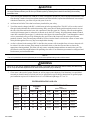
FILTER OPERATIONAL DATA
P/N 191807
FILTER
MODEL
NUMBER
FILTER
MODEL
(Sq. Ft.)
NSP-24
TURNOVER CAPACITY
FLOW RATE
(GPM)
(Gallons)
(Based on 2.0 GPM/Sq. Ft.)
Residential
2.5 GPM/Sq. Ft.
Public
2.0 GPM/Sq. Ft.
6 Hrs.
8 Hrs.
10 Hrs.
12 Hrs.
24
60
48
17,280
23,040
28,800
34,560
NSP-36
36
90
72
25,920
34,560
43,200
51,840
NSP-48
48
120
96
34,560
46,080
57,600
69,120
NSP-60
60
150
120
43,200
57,600
72,000
86,400
NSP-72
72
150
144
51,840
69,120
86,400
103,680
2
Rev. C 12-30-03
SECTION II. FILTER INSTALLATION.
WARNING
THIS FILTER OPERATES UNDER HIGH PRESSURE. WHEN ANY PART OF THE CIRCULATING
SYSTEM, e.g., CLAMP, PUMP, FILTER, VALVE(S), ETC. IS SERVICED, AIR CAN ENTER THE SYSTEM
AND BECOME PRESSURIZED. PRESSURIZED AIR CAN CAUSE THE LID TO BE BLOWN OFF
WHICH CAN RESULT IN SEVERE INJURY, DEATH, OR PROPERTY DAMAGE. TO AVOID THIS
POTENTIAL HAZARD, FOLLOW THESE INSTRUCTIONS.
A.
1.
BEFORE REPOSITIONING VALVE(S) AND BEFORE BEGINNING THE ASSEMBLY, DISASSEMBLY,
OR ADJUSTMENT OF THE CLAMP OR ANY OTHER SERVICE OF THE CIRCULATING SYSTEM: (A)
TURN THE PUMP OFF AND SHUT OFF ANY AUTOMATIC CONTROLS TO ENSURE THE SYSTEM
IS NOT INADVERTENTLY STARTED DURING THE SERVICING; (B) OPEN THE AIR RELIEF VALVE;
(C) WAIT UNTIL ALL PRESSURE IS RELIEVED.
2.
WHENEVER INSTALLING THE FILTER CLAMP FOLLOW THE FILTER CLAMP INSTALLATION
INSTRUCTIONS EXACTLY.
3.
ONCE SERVICE ON THE CIRCULATING SYSTEM IS COMPLETE FOLLOW SYSTEM RESTART
INSTRUCTIONS EXACTLY.
4.
MAINTAIN CIRCULATION SYSTEM PROPERLY. REPLACE WORN OR DAMAGED PARTS
IMMEDIATELY, e.g., clamp, pressure gauge, valve(s), O-rings, etc.
5.
BE SURE THAT THE FILTER IS PROPERLY MOUNTED AND POSITIONED ACCORDING TO
INSTRUCTIONS PROVIDED.
GENERAL INFORMATION.
1. Check carton for any evidence of damage due to rough
handling in shipment. If carton or any filter components are
damaged, notify freight carrier immediately.
2. After inspection, carefully remove filter components from
carton.
3. The filter should be mounted on a level concrete slab. Position
the filter so that instructions, warnings and the pressure gauge
are visible to the operator. It also should be positioned so that
the piping connections, control valve and drain port are
convenient and accessible for servicing and winterizing.
Table 1.
Model
184941
184942
184943
184944
184945
Size
24
36
48
60
72
sq.
sq.
sq.
sq.
sq.
ft.
ft.
ft.
ft.
ft.
Vertical
Clearance Req.
NSF
61 in.
67 in.
73 in.
79 in.
85 in.
yes
yes
yes
yes
yes
4. Provide space and lighting for routine maintenance access. Do not mount electrical controls over filter. Install
electrical controls (e.g., on/off switches, timers, control systems, etc.) at least five (5) feet from the filter. This
will allow you enough room to stand clear of the filter during system start up.
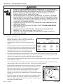
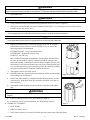
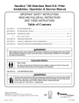
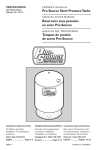
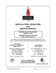
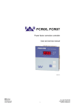
5. Allow sufficient clearance around the filter to permit visual verification that the clamp is properly installed around
the tank flanges, see Figure 1.
6. Allow sufficient space above the filter to remove the filter lid for cleaning and servicing. This distance will vary
with the model of filter you are using. See Table 1. for the required vertical clearance.
7. Filter plumbing connections are provided with an O-ring seal. If you have a
Multi-port Valve, assemble the valve to tank, being sure O-rings on valve
fittings are in place and are clean. To avoid damage to the O-rings, use
only a silicone base lubricant, applied lightly, such as silicone grease,
Mytilube or similar product on O-rings and O-ring grooves prior to
assemble. Do not use pipe joint compound, glue or solvent on the bulkhead
connections.
8. If you have a two position slide valve, align the valve with tank so that the
handle is toward the top of the tank, push valve into ports and turn the
valve nuts snugly on tank fittings. It is not necessary to cinch valve nuts to
tank fitting beyond hand tightness.
Rev. C 12-30-03
3
Figure 1.
P/N 191807
9. Assemble piping and pipe fittings to pump and valve. All piping must conform to local and state plumbing and
sanitary codes.
10.
Use Teflon tape or Plastojoint stick on all male connections of pipe and fittings. Use only pipe compounds suited
for plastic pipe. Support pipe to prevent strains on filter, pump or valve.
11.
Long piping runs and elbows restrict flow. For best efficiency use the fewest possible fittings, large diameter pipe
(at least 1½", preferably 2") and locate equipment as close to the pool as possible.
12.
A check valve is recommended between the filter and heater to prevent hot water "back up" which will damage
the filter and valve. Another check valve is recommended between the filter and the pump to prevent D.E. from
migrating back to the pool when the filter is off.
13.
The maximum operating pressure of this unit is 50 pounds per square inch. Never operate this filter above this
pressure or attach a pump to this filter that has more than 50 psi shut off pressure.
14.
Never install a chlorinator upstream of the filter - always downstream and with a check valve in between the
chlorinator and filter.
15.
A positive shut off valve is not recommended at the outlet of the filtering system. If the system is ever run with
such a valve closed, the internal air relief system becomes inoperative and an explosive situation could exist.
Additionally, running the system with no flow will seriously damage the equipment.
16.
A positive shut off valve is also not recommended at the waste port of the valve. If the system is ever run with
such a valve closed, the filter pressure will go abnormally high and increase the risk of vessel separation.
Additionally, running the system with no flow will seriously damage the equipment.
17.
Never store pool chemicals within 10 ft. of your pool filter and pump. Pool chemicals are corrosive and should
always be stored in a cool, dry and well ventilated area.
WARNING
Chemical fumes and/or spills can cause sever corrosive attack to the filter and pump structural metallic components.
Structurally weakened filter components can cause filter or valve attachments to blow off and could cause severe
bodily injury or property damage.
B. INITIAL START-UP.
1. On a new pool, clean the pool before filling with water. Excess dirt and large particles can cause damage to pump
and filter.
2. Check clamp assembly for tightness. See Filter Disassembly and Assembly procedures.
3. Move valve handle to filter position. Open air bleeder screw (Item 1) on the filter top. Check pump strainer
pot to be sure it is full of water. Replace pump lid.
WARNING
Conditions where air enters the filter and the tank lid is not installed properly can cause the lid to separate and could
cause serious bodily injury and/or major property damage. Always stand clear of the filter when it is in operation or
when power to the pump is turned on.
4. Open all suction and return line valves. Stand clear of filter during the following operations.
5. Start pump. The tank will fill with water and expel air from air bleeder.
6. Remove the skimmer lid, put the recommended amount of diatomaceous earth (D.E.) into the skimmer. The D.E.
will be drawn into the filter and deposited evenly upon the grid elements. Now the filter is providing the pool with
bright, clean water.
NOTE
Do not operate filter without D.E. charge for more than two minutes. Do not use more than the recommended amount of D.E. in your filter.
P/N 191807
4
Rev. C 12-30-03
C. D.E. RECOMMENDATION.
The amount of D.E. should be 1 pound for each 10 square feet of filter
area or:
7. On a new pool installation, it will require approximately one week to
obtain and maintain the water clarity of which your filter is capable.
It is recommended to disassemble and clean the filter after initial
pool clean up (approximately 48 hours of operation). Follow the
instructions given in this manual for disassembly, cleaning and
reassembly.
8. Be sure to note the operating pressure of the filter when it is clean
and properly charged with D.E. As the filter removes dirt from the
pool, the pressure will gradually increase. As a guide, when the
pressure has increased 7 to 10 psi from the initial reading, it is time
to backwash the filter.
MODEL
POUNDS OF D.E.
NSP-24
2.4
NSP-36
3.6
NSP-48
4.8
NSP-60
6.0
NSP-72
7.2
NOTICE: ½ pound if D.E. will fill a 13 oz. coffee can.
Alternately another method for determining when to backwash the filter is by judging a drop in the amount of
water flowing from the filter by observing the flow from the inlet fittings in the wall of the pool. As a general rule,
backwashing is needed when the flow rate becomes about 2/3 the rate of a clean filter.
D. FILTER DISASSEMBLY/ASSEMBLY.
Before Disassembling Filter:
Backwash filter according to instruction under "Filter Backwash Procedure" but stop after instruction #7. Do not
precoat with new D.E.
E. DISASSEMBLY.
1. Be sure pump is turned off and all pressure has been released from system.
WARNING
Releasing clamp with pressure on system will cause tank lid to blow off, causing severe injury or property damage! NEVER
adjust, tighten or loosen band clamp when tank is under pressure! Turn off system and release pressure before working on the
filter.
2. Remove filter drain plug and drain all water from tank.
WARNING
Clamp hardware and filter surface could have sharp edges which can cause bodily injury if improperly handled. Please use
caution when performing the following procedures:
3. To remove the clamping ring, partially unscrew the adjustment knob and release the head of the T-bolt from the
slotted bracket.
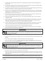
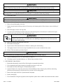
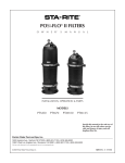
4. Remove the tank lid with screwdriver or with a tool available from the manufacturer. Avoid cutting rubber O-ring
or bending of lid or tank O-ring channel. See Figure 1.
F. ASSEMBLY.
Lid
1. Thoroughly clean air relief filter screen on top of manifold EVERY time filter
is opened. Be sure to remove all debris from screen.
O-ring
Filter Lid Opener
2. Inspect tank seal (or tank o-ring, Item 35) for cuts, nicks, etc. If damaged,
replace with a new one.
3. Clean tank seal area of tank shell (both halves) and tank seal.
4. Inspect, clean and lubricate the O-ring (Item 25) on the upper pipe assembly
(Item 17).
Rev. C 12-30-03
5
Tank
(2)
(1)
Figure 1.
P/N 191807
5. Replace holding wheel over center rod; place washer over rod and turn holding wheel until elements spread to
widest gap. Replace washer or hold-down spring (800 series only) then screw wing nut on rod. Do not tighten
nut beyond finger tight. Be sure to clip air vent tube back into slot on holding wheel. Clean vent tube screen
cap of any debris.
6. Remove rubber tank seal and clean both tank seal and channel. Lubricate tank seal with a non-water soluble
grease or silicone lubricant and replace tank seal in channel.
7. Clean the inside surface of the tank lid where it seals against the tank seal. Place lid on tank; push down on lid to
seat in place.
8. Replace the clamping ring. Engage the head of the T-bolt into the slotted bracket and tighten the adjustment knob.
(Hand tighten only.)
WARNING
Do not over tighten the clamp band. Tightening the clamp band beyond recommended procedures may
damage the clamp band and cause unexpected failure, sudden release of pressure and injury or damage.
Over tightening may also deform tank seal, causing leakage at band clamp. Corroded components cannot be
repaired and must be replaced. If you are experiencing corrosion, consult your pool service company or dealer.
WARNING
Always visually inspect filter components during normal servicing to insure structural safety. Replace any item which is
corroded, bent or otherwise visually deteriorated. Deteriorated filter components can allow the filter top or attachments to blow
off and could cause severe bodily injury or property damage.
G. FILTER CARE.
Keep pool water pH at the recommended levels (7.2 to 7.6) as well as other pool chemicals at their proper levels to
avoid deterioration of the stainless steel tank. The tank is stainless steel, but is not corrosion proof it the pool chemistry
is allowed to act aggressively. Under such conditions the steel can experience pitting which will be most apparent in the
flange area where the O-ring seats and seals the two halves of the filter. To minimize this tendency, it is recommended to
keep the flanges clean of surface corrosion by removing any corrosion with fine emery cloth or stainless steel wool, (do
not use steel wool) and to coat the O-ring with a substance such as petroleum jelly, silicone grease, Mytilube or similar
product. If corrosion is allowed to progress, the filter will eventually leak at the O-ring seal. This process cannot be
arrested or corrected by tightening the closure band, though that may temporarily stop the leak.
H. CLEANING FREQUENCY.
The filter on a new pool should be backwashed, disassembled and cleaned after approximately 48 hours of operation to
clean out plaster dust and/or construction debris.
Once a new pool has been established, the dirt collected will gradually increase the filter pressure. When the filter
pressure increases 7 to 10 psi over the initial pressure or when the flow has been reduced by about 1/3 from when the
filter was clean, it is time to backwash the filter. Different areas and water conditions will have different normal cleaning
intervals.
If at any time the starting pressure after backwashing the filter indicates 2 to 6 psi higher than normal starting pressure, it
is time to perform a manual filter cleaning or a chemical cleaning procedure in the worst cases.
It is a good idea to disassemble the filter and perform a chemical cleaning procedure twice a year to remove accumulated
body oils, etc.
In areas that have freezing winter temperatures, protect equipment by backwashing and either manually cleaning or
chemically cleaning before winter storage. Be sure all water is drained from the filter using the drain plug. The air bleeder
must be opened as well as all other valves.
P/N 191807
6
Rev. C 12-30-03
I. FILTER BACKWASH PROCEDURE.
WARNING
To prevent equipment damage and possible injury, turn pump OFF before changing valve position.
NOTE
When backwashing with a separation tank, see Separation Tank Owner's Manual for instructions.
1. Stop pump. Ensure that the backwash line is open and any valving is adjusted to allow the free flow of water.
2. Change valve positions.
a. If using Multi-port Valve, set to backwash position.
b. If using Two-Position Slide Valve, raise handle to fully extended position.
3. Stand clear of filter.
4. Start pump, this will circulate water backwards through the filter to flush D.E. cake and contaminants into the
separation tank or to waste.
5. If system has a sight glass, backwash until water in glass runs clear.
6. If system does not have a sight glass:
a. Backwash one minute.
b. Stop pump and change valve position.
1. If using Multiport Valve, set to rinse position.
2. If using Two-Position Slide Valve, push handle down to filter position.
WARNING
To prevent equipment damage and possible injury, turn pump OFF before changing valve position.
c. Stand clear of filter.
d. Restart pump, run for one minute.
e. Repeat steps a, b, c, and d three times.
Cycling is effective when cake and contaminants are difficult to break and flush out of the filter.
CAUTION
Do not vacuum pool while backwashing filter. Vacuum hose can restrict flow and prevent proper backwashing.
7. Stop pump.
8. Open air bleeder screw and release all pressure from tank and system.
9. Follow "Initial Start-Up" procedure to restart system.
10.
Compare pressure reading on gauge with reading recorded after initial start-up. The two readings should be very
close; if not, do "Manual Filter Cleaning Procedure".
J. MANUAL FILTER CLEANING.
NOTE
At least once a year, disassemble and clean filter regardless of operating pressure readings. This can be done conveniently while winterizing
pool in cold climates. Use this method regularly if no means of backwashing is available.
BEFORE DISASSEMBLING FILTER:
1. Backwash filter as recommended but do not precoat with new D.E.
2. STOP PUMP.
3. OPEN air bleeder screw.
4. WAIT until all pressure is released from filter tank and system before loosening clamp.
Rev. C 12-30-03
7
P/N 191807
WARNING
Releasing clamp with pressure on system will cause tank lid to blow off, causing severe injury or property damage! NEVER adjust,
tighten or loosen band clamp when tank is under pressure! Turn off system and release pressure before working on the filter.
5. Disassemble filter.
WARNING
To avoid severe injury or property damage, follow instructions exactly under "Disassembly" (Page 5).
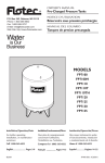
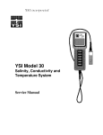
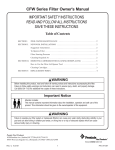
6. Grasp element assembly at top manifold using hand holds and lift to remove it (Figure 2).
7. Hose down element assembly and clean with bottle brush (Figure 3). Use detergent solution or filter cleanser
available from a pool service store.
NOTE
To avoid damaging fabric, do not allow filter element to rub on concrete or any abrasive surface during cleaning.
NOTE
Do not expose element cloth to direct sun for long periods. Direct sun will cause cloth to deteriorate.
8. Inspect grid cloth for tears, calcification, plugged areas, etc. If necessary,
soak element in filter cleanser to remove buildup of oils, etc. One of the
following cleaners is recommended:
FILTER-CLEANSE - Great Lakes Biochemical
FILTER-FREE - Hydrotech Chemical Corp.
KLEEN-IT - Bio Lab, Inc.
Mix a solution following the manufacturer's instructions on the label. Place
the entire grid assembly in a plastic container and add the solution so the
entire grid assembly is submerged. Allow to stand overnight (12 hours). The
following day, wash with a hose and remove all of the solution from the grid
so it does not return to the pool. If calcified, perform the chemical cleansing
procedure described under "Chemical Cleaning Procedures".
9. Thoroughly clean air relief filter screen.
10.
With filter drain open, hose down the internal portion of filter and thoroughly
clean sealing area of tank halves.
11.
Replace the grid assembly by setting the manifold opening directly over the
connector pipe. Push down on the grid assembly and check to see that it is
seated properly.
12.
Thoroughly clean drain plug seal and sealing area and replace and tighten
plug.
Figure 2.
WARNING
To avoid severe injury or property damage, follow instructions exactly under "Assembly"
(Page 5)!
13.
If unit is returning to service, see "Initial Start-up" (Page 4).
14.
If cleaning is part of seasonal shutdown, see "Winterizing" (Page 9).
Figure 3.
K. CHEMICAL CLEANING.
1. STOP PUMP.
2. OPEN air bleeder screw.
3. WAIT until all pressure is released from filter tank and system before loosening clamp.
P/N 191807
8
Rev. C 12-30-03
WARNING
Releasing clamp with pressure on system will cause tank lid to blow off, causing severe injury or property damage! NEVER adjust,
tighten or loosen band clamp when tank is under pressure! Turn off system and release pressure before working on the filter.
CAUTION
Do not expose element cloth to direct sunlight for long periods. Direct sunlight will cause the cloth to deteriorate. To avoid
damaging fabric, do not allow filter element to rub on concrete or any abrasive surface during cleaning.
4. Disassemble Filter.
WARNING
To avoid sever injury or property damage, follow instructions exactly under "Disassembly" (Page 5)!
5. Disassemble and inspect element grid assemblies for tears and worn areas. Replace as needed.
6. Rinse each grid thoroughly with water.
7. Wash each grid with a mild soap solution. If necessary, soak element grids in filter cleaner to remove buildup of
oils, etc.
8. Rinse thoroughly to remove all soap film.
9. To remove mineral buildup from filter cloth, soak each element grid two to four hours in a solution of one part
muriatic acid to ten parts water. Some foaming may occur.
WARNING
Working with muriatic acid can be dangerous. When cleaning elements always wear rubber gloves and eye
protection. Add acid to water, do not add water to acid. Splashing or spilling acid can cause severe personal
injury and/or property damage.
10.
Rinse each element grid thoroughly with water.
11.
Reassemble element grids.
12.
Inspect inside of filter tank and remove all debris remaining after backwashing.
13.
Thoroughly clean air relief screen on top of manifold. Be sure to remove all debris from screen.
14.
Follow "Filter Assembly" procedure (Page 5).
WARNING
To avoid severe injury or property damage, follow instructions exactly under "Assembly" (Page 5)!
15.
If unit is returning to service, see "Initial Start-up" (Page 4).
16.
If cleaning is part of seasonal shutdown, see "Winterizing" procedures, below.
L. WINTERIZING PROCEDURE
1. Backwash and manually clean the filter following the recommended procedures.
2. We recommend removing the internal grid assembly and store in a dry area.
3. Reassemble the filter following the recommended procedures.
4. Open air bleeder valve. Open all system valves. Position Multiport Valve between port positions (winterizing
position) to allow passage to all ports and relieve pressure on the sealing gasket.
5. Remove drain plugs from filter, separation tanks and pumps.
6. Drain system piping.
7. We recommend covering the equipment with a tarpaulin or plastic sheet to inhibit deterioration from the weather.
Rev. C 12-30-03
9
P/N 191807
SECTION III.
TROUBLE SHOOTING.
System Problem
Cause
D.E. Leaking back to pool.
Remedy
1. After backwashing and re-coating the
filter with D.E. some amount of
"puffback" is normal.
2. Damaged Grid or O-ring in filter
assembly.
3. Improper assembly of internal parts.
4. Missing or defective check valve.
The D.E. will eventually be filtered out of the pool. No action necessary.
Allow pressure to build to 5-11 psi above clean filter condition before
backwashing, see SECTION II-F.5.
Correct assembly of parts.
Install or repair check valve.
Pool water not sufficiently clean. 1. Improper precoat of D.E. on grids.
2. Inadequate turnover rate.
3. Pool chemistry not adequate to inhibit
algae growth.
Use recommended amount of D.E.
Consult dealer or pool service technician.
Maintain pool chemistry or consult pool service technician.
High filter pressure after
backwash.
1. Insufficient backwashing.
2. Filter cloth plugged with D.E. and
contaminants.
3. Filter cloth plugged with mineral deposits.
4. Partially closed valve or restriction in
return line.
Backwash until water runs clear.
Manually clean filter grids.
Return flow to pool diminished
and low filter pressure.
1. Obstruction in pump hair and lint strainer.
2. Obstruction in pump.
3. Obstruction in suction line to pump.
Clean basket in strainer.
Disassemble and clean pump.
Clean skimmer basket. Remove obstruction in lines. Open valves in suction line.
Requires frequent backwash
(short filter cycle).
1. Improper backwash.
2. Pool chemistry not adequate to inhibit
algae growth.
3. Improper precoat of D.E. on grids.
4. Plugged girds.
5. Flow rate too high.
Backwash until water runs clear.
Maintain pool chemistry or consult pool service technician.
1. Improper torque on closure band
hardware.
2. Debris contamination on tank seal and
flanges.
3. Cut or damaged tank seal.
4. Corrosion pits on flanges.
Reassemble clamp following procedure under Assembly on page 5.
Leakage at the clamp.
Chemically clean filter grids.
Open valve or remove obstruction in return lines.
Use recommended amount of D.E.
Manually clean or chemically clean as required.
Restrict flow to capacity of filter.
Clean tank seal and flanges. Lubricate tank seal.
Replace tank seal.
Replace tank and consult pool service technician for source of corrosion.
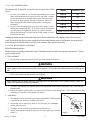
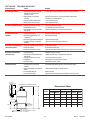
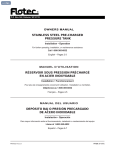
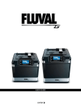
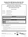
INTERNAL
STAND PIPE HT.
CLEARANCE TO REMOVE GRIDS
Dimensional Sheet
C
MODEL
A
OUTLET
INLET
DRAIN
2" FEMALE
PIPE THD.
16-1/2"
9"
B
A DIM.
B DIM.
C DIM
INCHES METRIC INCHES METRIC INCHES METRIC
NSP-24
32
813 mm
61
1549 mm
5 1/2
140 mm
NSP-36
38
965 mm
67
1702 mm
11 1/2
292 mm
NSP-48
44
1118 mm
73
1854 mm
17 1/2
445 mm
NSP-60
50
1270 mm
79
2007 mm
23 3/8
594 mm
NSP-72
56
1422 mm
85
2159 mm
29 3/8
746 mm
18"
INLET AND OUTLET QUICK CONNECT FITTINGS
ARE 1-1/2" SOCKET / 2" SOCKET
P/N 191807
10
Rev. C 12-30-03
SECTION IV. TECHNICAL DATA
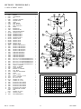
A. REPLACEMENT PARTS
DESCRIPTION
AIR RELIEF ASSEMBLY
BLEEDER
O-RING BLEEDER
CAP
VALVE BODY - MACHINED
PRESSURE GAUGE
O-RING
LABEL, WARNING
SHELL-TOP, NSP-24
SHELL-TOP, NSP 36-72
SPACER
BULKHEAD NUT
STRAINER-AIR VENT
MANIFOLD GRID COMPLETE
GRID-PARTIAL, NSP-24
GRID-PARTIAL, NSP-36
GRID-PARTIAL, NSP-48
GRID-PARTIAL, NSP-60
GRID-PARTIAL, NSP-72
GRID-FULL, NSP-24
GRID-FULL, NSP-36
GRID-FULL, NSP-48
GRID-FULL, NSP-60
GRID-FULL, NSP-72
GRID ASSY.-COMPLETE, NSP-24
GRID ASSY.-COMPLETE, NSP-36
GRID ASSY.-COMPLETE, NSP-48
GRID ASSY.-COMPLETE, NSP-60
GRID ASSY.-COMPLETE, NSP-72
PIPING ASSY.-UPPER, NSP-24
PIPING ASSY.-UPPER, NSP-36
PIPING ASSY.-UPPER, NSP-48
PIPING ASSY.-UPPER, NSP-60
PIPING ASSY.-UPPER, NSP-72
ROD 5/16 X 15-1/2 in. MANIFOLD RETAINER, NSP-24
ROD 5/16 X 21-1/2 in. MANIFOLD RETAINER, NSP-36
ROD 5/16 X 27-1/2 in. MANIFOLD RETAINER, NSP-48
ROD 5/16 X 33-1/2 in. MANIFOLD RETAINER, NSP-60
ROD 5/16 X 39-1/2 in. MANIFOLD RETAINER, NSP-72
O-RING - 2 in. BULKHEAD
SPACER - 2 in. EXTERNAL
O-RING - BULKHEAD
BULKHEAD - 2 in. W/GROOVE
FOOT - NSP/PF
PIPING ASSY. LOWER W/DRAIN
O-RING
PLUG - 2 in. DRAIN
SPACER - 2.8 in. DIA. X 1/4 in. PVC
NUT - 2 in. BULKHEAD
NUT - 5/16 in., 16 s/s
WASHER 5/16 in. s/s FLAT
WASHER 5/16 in. s/s LOCK
BOTTOM ASSY., NSP-24/w PIPING
BOTTOM ASSY., NSP-36/w PIPING
BOTTOM ASSY., NSP-48/w PIPING
BOTTOM ASSY., NSP-60/w PIPING
BOTTOM ASSY., NSP-72/w PIPING
CLAMP-RING ASSY., INCLUDES:
KNOB
WASHER 5/16 in. s/s FLAT
TANK SEAL (O-RING)
GRID, RETAINER/BAFFLE
QTY.
1
1
1
1
1
1
2
1
1
1
1
1
1
1
1
1
1
1
1
7
7
7
7
7
1
1
1
1
1
1
1
1
1
1
2
2
2
2
2
2
1
1
1
1
1
2
1
1
1
4
2
2
1
1
1
1
1
1
1
1
1
1
4
3
5
2
6
1
7
8
9
29
10
30
11
12
13
14
34
15
33
17
35
16
26
18
32
19 20 21
22
30, 31
29
28
23
19
27
24
26
25
40
35
PRESSURE DROP In FT. of W.C.
ITEM PART NO.
1
273550
2
273512
3
273513
4
273501
5
273550
6
155050
7
154492
8
272546
9
191808
9
191821
10
273505
11
154412
12
172855
13
192193
14
59001000
14
59001700
14
59002300
14
59002900
14
59003500
15
59001100
15
59001800
15
59002400
15
59003000
15
59003600
16
192324
16
192325
16
192326
16
192327
16
195060
17
194981
17
194982
17
194983
17
194984
17
194985
18
192182
18
192183
18
192184
18
192185
18
195002
19
154492
20
194893
21
192320
22
194801
23
154722
24
194913
25
192323
26
195829
27
154747
28
154412
29
192013
30
072173
31
174955
32
197092
32
197096
32
197093
32
197094
32
197095
33
191805
076033
072173
34
071442
35
192194
NSP-60
NSP-72
30
25
20
15
10
NSP-24
NSP-36
NSP-48
5
0
10
20
30
40
50
60
70
80
90
100 110 120 130 140 150 160
CAPACITY In U.S. GPM
Rev. C 12-30-03
11
P/N 191807
SAVE THESE INSTRUCTIONS.
Pentair Pool Products
1620 Hawkins Ave., Sanford, NC 27330 • (919) 774-4151
10951 West Los Angeles Ave., Moorpark, CA 93021 • (805) 523-2400
P/N 191807
12
Rev. C 12-30-03