1
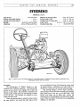
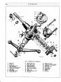
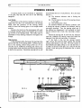
SECTION J
STEERING
NUMBER
1
DATE
SUBJECT
CHANGES
AUSTIN
A40
SERVICE
MANUAL
J/1
STEERING
GENERAL DATA
Type of Gear
... ... ,..
Cam and Lever
... ... 14 to 1
Steerhg Gear Ratio (Saloon) ...
...
... 12 to 1
Steering Gear Ratio (Sports) ...
Bearings ...
... ... Ball Race akd Felt Bush
Adjustrnent
...
... Screw & Packwood Shims
Diameter of Steering Wheel
... 17-ins. (43.18 cm.)
Turning Circle (Cars) ...
. ..
37-ft. (1 1.278 m.)
Turning Circle (Coinmercials) ...
38-ft. (1 1 .S82 m.)
Track Toe-in
...
... fs-A-in. (1.5875-3.175 mm.)
Austin Ball Type
Steering Comections
... ...
Fig. 1. A general view of the steering linkage for a right-hand model. On left-hand steering models the positions of the
steering box and idler shaft are reversed.
Description
The steering gear. of "Bishop" design, is a selfcontained unit of extreme simplicity. The steering tube
revolves a cam which in turn engages with a taper peg
fitted to a rocker shaft. This assembly is enclosed in an
oil-tight casing, which carries two ball bearings at either
end of the cam. The bearings are designed to carry
radial and thrust loads.
When the steering wheel is turned the tube revolves
the cam. which in turn causes the taper peg to move
over a pre-determined arc, thus giving the rocker shaft
its desired potion. Attached to the rocker shaft is a
double lever which links up with the steering linkage.
The steering linkage is of the "three cross-tube"
type, having a centre cross-tube connecting the steering
gear double lever to the arm on the idler shaft. Two
shorter cross tubes, one on either side, connect the
steering arms to the steering gear and idler levers respectively. These two shorter cross-tubes are more generally
referred to as side tubes.
512
STEERING
Maintenance
Lubrication of the oil nipples on the steering
connections and swivel bearings is most important to
maintain accurate steering.
Approximately every 500 miles, use the oil gun and
recommended oil to charge the following points with
1ubricant:-
(a) Steering side and cross-tubes-6 nipples.
(b) Lower wishbone arm outer bearing-2 nipples.
(c) Swivel pin bushes-4 nipples.
(d) Steering idler-1 oil filler plug.
The steering gear should be topped up with recommended oil to the top of the filler plug opening approximately every 5,000 miles.
STEERING CONNECTIONS AND IDLER
Adjusting the Track
The track is best checked by means of the Dunlop
Optical Alignment Gauge No. 9, particulars of which
can be obtained from the Dunlop Rubber Company
Limited, Fort Dunlop, Erdington, Birmingham.
The cross-tube is threaded right-hand at one end
and left-hand at the other, so that the track adjustment
can be made by simply rotating the tube in the required
direction after releasing the locknuts. On some models
the adjustment is secured by clainps and pinch bolts.
Under no circumstances should the setting of those
side-tubes that are adjustable, be disturbed for tracking
purposes except after a dismantling of the steering link-
ages. They should then be reset to 11%-in. measured
between the ball pins. Always re-tighten the locknuts
at each end of the cross-tube after an adjustment has
been made.
Side and Cross-Tubes
The side and cross-tubes are held in position by a
castellated nut and split pin at each end. On later models
a washer is fitted beneath the castellated nut. It is essentia1 that this washer be replaced on reassembiy, otherwise
the nut, when tightened, will be screwed too far down
the thread to enable the split pin to lock the nut in
position.
Fig. 2. Chxking the wheel track with the Dunlop Optical Alignment Gauge No. 9.
A. Wheel pointer. B. Attachment hook. C. Mirror. D. Calibrated scale. E. View box.
STEERING
Fig. 3. The toe-in rnust be adjusted rothat A is
inch less than B.
6 to
1I
J/3
a very fine adjustment. Adjustments should be made and
checked regularly, otherwise undue slackness will cause
a deformity of the ball pin thereby making further
adjustment impossible.
To make an adjustment, remove the split pin, lightly
screw it back to the first alignment of the split pin hole
and castellation. The ball should then be able to move
freely in the socket.
Always ensure that the rubber boot fits snugly in
the groove provided for it in the tube end.
An alternative type of connection is employed on
some models. This type is self-adjusting and requires
no attention other than lubrication at the prescribed
intervals.
To remove the tubes, witlidraw the split pin and
release the nut at each end of the tube and then carefully
tap the tubes clear of the levers to which they are attached. When removing one of the connections from
either end of the steering gear double lever, always
support the lever to prevent any shock from being
transmitted to the steering gear where damage may be
caused.
Tube Connections
Some steering side and cross-tubes are equipped with
the Austin patent ball and socket connections which are
screwed into the ends of the tubes and can be adjusted
to take up wear. These connections consist of a threaded
and castellated lower socket screwed into position and
locked by a split-pin. The body of the tube-end has
four split pin holes drilled, vernier-pattern, at a different
pitch from the castellations in the socket, thus permitting
Fig. 5. Showing the adjustable type of the Austin
patented ball and socket connection.
Removing- the Double Levers
These are held to the steering gear rocker shaft and
to the idler shaft respectively by a nut and split pin.
With the removal of the nut and split pin, the double
levers can be withdrawn from their splined shafts by
using an extractor. See Fig. 1 l. Never attempt to lever
or hammer the steei-inggear double lever from the rocker
shaft, otherwise serious damage to the steering gear
may result.
Fig. 4. Illusirating the self-adjusting type ball and
socket connection.
Removing the Idler
With the side and cross-tubes disconnected the idler
can be detached from the chasis. It is secured by
three bolts, inserted from the inside of the dumb-iron
and terminating in the three tapped holes in the idler
flange. Support the idler with the hand and unscrew the
setscrews until their threads are clear of the holes,
when the idler can be detached.
phosphor bronze bushes. At its lower end the shaft
incorporates a spline to take the double lever and a
portion of screw thread to take the lever securing nut.
The idler shaft is drilled for passing lubrication to the
bearing bushes.
No adjustment is necessary for this type of idler.
Refitting the Idler
The refitting of the idler is generally a reversal of
the removal procedure, but care should be taken to
ensure that it is secured firmly against the frame by
means of the three bolts with spring washers beneath their
heads.
Refitting the Double Levers
There is a location mark in the double lever and a
corresponding mark on the end of the steering gear
rocker shaft. When refitting the double lever make sure
that these marks coincide. Press the lever on to the
splined shaft and sedure it with the castellated nut,
plain washer and split pin.
To check for the correct fitting of the lever, ensure
that there is a distance of approximately 3-ins. between
the underside of the frame side member and the upper
machined face of the rear arm of the lever.
Press the lever on to the splined shaft and secure
Fig. 6. Steering idler parts explodd
Cap setpin and washer. 8. Washer.
Idlrr cap.
9. Double lever.
Oil plug.
10. Slotted nut and pin.
Joint washer.
11. Washer.
Idler body.
12. Lower bush bearing.
6. Idler shaft.
13. Upper bush bearing.
7. Cork seal.
l.
2.
3.
4.
5.
Dismantling and Assembling the Idler
The idler top cap is secured to the body by three
setpins and has a joint washer inserted between cap and
body. Lubrication is effected by removing the oil plug
in the cap and injecting oil into the body.
Internally 'the body' has a recess in the head and a
plain bore right through. Twp phosphor bronze bush
bearings, with interna1 oil grooves, are pressed into
position, one at the top and the other at the bottom of
the body.
At the lower end of the body a cork sea1 butts up to
the lower bearing bush and is retained in position by
a steel washer, which in turn, is secured by the bore of
the body being "peened" ovqr. By removing this burr,
with the aid of a hand scraper, the washer and cork sea1
can be extracted.
The idler shaft can be removed by hand once the
body cap has been released. The flange of the idler shaft
locates in the recess within the body head and the two
highly finished portions of the shaft rotate within the
Fig. 7. Checking the alignment of a swivel arm
(method 2).
STEERING
J/5
it with the slotted nut, plain washer and split pin. Note
that location marks are not necessary for this lever
and shaft, but the clearance between the underside of
the frame member and the rear machined face of the lever
should be the same as for the lever fitted to the steering
box shaft.
The wheels must be in the straight-ahead position
while these two levers are being fitted.
Refitting the Side and Cross-Tubes
First connect the two side-tubes to their respective
steering arms and levers. Fit the cross-tube and ensure
that both the side and cross-tube securing nuts are tight
and split pinned.
Swivel Arms
The swivel arms connecting the swivel axles to the
steering side-tubes may be checked for misalignment in
the following way:(1) Place a rule along the brake backplate so that
it projects alongside the arm. The distance between the
centre of the ball pin locating hole and the rule should
be 4-in. plus or minus Ig-in.
(2) Place a straight-edge across the centre of the
bolt holes used to secure the arm to the swivel axle.
The distance between the straight-edge and the lower
face of the arm machined face against which the ball
pin nut fits-should be &in. plus or minus Ig-in. (See
Fig .7.)
Removing the Steering Gear
To remove the steering gear and column complete
from the car, first remove the upper portion of the direction indicator control tube from within the steering
column. Release the three grub screws which pass
through the steering hub to secure the horn quadrant.
At the steering box end of the column, the horn and
indicator electrical cables should be disconnected at the
nearest snap connections. The horn quadrant and short
stator tube may then be withdrawn complete with cables.
It will be noticed that the short tube has a number
of indentations on its outer diameter, thus forming lugs
internally, which locate in the slot of the long tube
remaining within the steering column.
Finally remove the locknut retaining the steering
wheel in position. With a sharp jerk upwards the wheel
may be freed from the splines and so removed from the
column.
The gear change lever and rod are secured to the
steering column by means of a clamp bracket, therefore
the gear change must be released from the steering
column. This operation simply entails the removal of
the two Allen screws from the bracket.
Fig. 8. Checking a swivel arrn for misalignrnent
lmethod 1).
Holding the steering column in place within the
body there is a "U" bracket which is secured to the
underside of the fascia panel. To dismantle this bracket,
release the two setpins and remove the "U" bracket
complete with its packing.
Next jack up the car at its front end and remove the
bumper and apron, two operations that have been
detailed under the Bodywork section of this manual.
(In the case of the Sports and Commercials, it is only
necessary to remove the front number plate.)
Remove the double lever from the rocker shaft, as
previously described. Finally disengage the steering box
from its mounting by removing the single nut and bolt
and relative washers, and the two rear setpins and spring
washers, al1 of which pass through the chassis side members, to the steering supporting bracket.
The steering gear complete with column may now be
withdrawn from the car by an outward movement and a
slight twisting to avoid the bodywork.
When replacing the steering, reverse the removal
procedure but do not tighten the box securing setpins
and single bolt, until the column has been secured within
the driving position.
STEERING
516
Fig. 9. Componenb of the studng b x .
1.
2.
3.
4.
5.
6.
7.
8.
9.
10.
Wlt washer.
Circlip.
Cork washer.
Steering inner wlumn.
Top cover setpin.
Rocker shaft adjusting screw.
Adjusting screw locknut.
Top cover.
Joint washer.
Steering gear housing.
I 1. Rmker shaft arm.
12. Peg for rocker a m .
13. Steering gear bracket.
14. Setpin and washer.
15. Bracket clamp bolt.
16. Clamp bolt locknuts.
17. Ball cups for bearings.
18. Ball and cap assemblies
19. Cam.
20. Joint washer.
21. M n g adjustment s h h s
22. End cover.
23.
24.
25.
26.
27.
28.
29.
30.
31.
32.
Setpin and washer.
Trafficator tube gland washer.
Trafficator tube securing nut.
Filler plug.
Filler plug washer.
Cork washer.
Retaining disc.
Double lever.
Washer.
Slotted nut.
--
STEERING
517
7
Dismantling
The top cover plate should be removed after extracting the three securing setscrews.
Tum the steering gear over and suitably support the
top face leaving the rocker shaft free to be lightly tapped
out using a soft metal drift. The following peg is a
drive fit in the rocker and need not be removed unless
showing an appreciable amount of wear.
Adjusting the Gear
The adjuster in the cover plate should be clackened
by releasing the locknut and unscrewing the screw a few
tums. The cover plate can then be fitted making sure
an oil-tight joint is obtained. The adjuster should be
screwed down until there is no free movement in the
straight ahead position of the gear and the adjustment
secured by the locknut.
Final adjustment should be made once the gear has
been reassembled to the chassis. It should be noted that
as wear in use is normally greater in the straight ahead
position than on lock, provision is made for this in the
design of the cam, and it will be found that there is
a slight end play towards each lock. It is essential,
therefore, that adjustment should be made in the
straight ahead position to avoid the possibility of
tightness.
The steering gear should be fiiled with recommended
gear oil via the filler plug situated at the rear righthand side of the steering box and then a final test
made to ensure that the movement is free from lock to
lock.
Fig. 10. Using Service Tool 18G 70 to withdraw a
tight stecring whecl.
Remove the four setpins securing the end cover
plate in position, and release the end cover. The complete unit should now be up-ended with the steering box
uppermost. By bumping the end of the inner shaft on a
block of wood, placed on the floor, the worm with its
two ball bearings will be displaced. The complete inner
column can then be withdrawn from the casing through
the open end of the steering box.
For extracting the felt bush at the top of the column,
use a piece of strong hooked wire, the hook pulling on
the under face of the bush. The fitting of a new bush is
simple ; smear the felt with heavy oil and press into
place.
Adjusting shims should be fitted behind the end
cover so that there is no end play on the column, but at
the same time they should not be pre-loaded, otherwise
damage to the ball races may ensue.
The rocker shaft may now be dropped into position,
ensuring that it is a good fit in its housing and that the
oil sea1 at the lower end of the trunnion is making
good contact.
HM. ase. A.
Fig. 11. Using .%i.vice Tool 1 8 6 75 to remove a
double lever.
J 18
STEERING
STEERING FAULTS
If steering faults are not attributed to adjustment
of the gear, they may fall into one of the following
categories.
Lost Motion
The amount of lost motion reaches its maximum at
either lock, but this is not normally felt at the steering
wheel, since the geometry of the steering always
tends to return the steering gear to the straight ahead
position.
Excessive lost motion in the steering gear will result
in unsteady steering, knocks and backlash al1 of which
can be felt at the steering wheel. This defect may be
attributéd to loose steering connections throughout the
linkage.
Tight Steering
If the steering is tight, disconnect the steering tubes
and test the feel of the steering wheel. Stiffness may be
due to the steering column being pulled out of line
and this can be verified by loosening the column supporting bracket under the fascia and allowing the column
to find its free position. Should the steering still be stiff
check whether this is so in al1 positions. If so, the cause
may be:(a) The direction indicator tube is fouling the
column.
(b) The felt bush at the top of the steering column
is too tight.
(c) The steering tube is bent.
To ascertain whether the direction indicator tube
is fouling the column, withdraw the indicator tube as
previously described. Turn the steering wheel and if
the stiffness has disappeared, it will probably be found
that the indicator tube is bent, thus requiring a replacement.
Should the steering still be stiff with the indicator
tube free, withdraw the steering wheel and check the
tightness of the felt bush and renew, if necessary.
If the bush is free but the steering remains
tight, remove the bush and check whether the steering
column pulls heavily to one side. The inner column is
fairly flexible and slight pulling to one side has little or
no effect on the feel of the gear, but it may be that the
column is bent thus giving no alternative but to renew
the column.
Fig. 12. Seclional views oí the steering gear.
l . Felt bush.
2.
3.
4.
5.
6.
Steering inner colurnn.
Steering gear housing.
Ball cup for bearing.
Rall cage-inner.
Cam.
7.
8.
9.
10.
I l.
12.
Ball cage-outer.
Ball cup for bearing.
Joint washer and shims.
End cover.
Securing setpin.
Rocker shaft.
13.
14.
15.
16.
17.
18.
Tdp cover setpin.
Rocker armpeg.
Rocker shaft adjusting screw.
Rocker shaft bearing.
Double lever.
Securing nut.
STEERING
Loose Steering
Loose steering is invariably attributed to end play
of the inner column, which can be rectified by the
removal of shims located behind the steering box end
cover plate, in a manner already described.
To check for this end float, disconnect the side and
J19
cross-tubes from the double lever and turn the steering
partly to the right or left lock. Then with the steering
wheel held to prevent it from turning, endeavour to tum
the double lever. Should the steering wheel have a
tendency to lift, it may be assumed that there is end
float of the gear.