1
SERIES JP-24 DISHWASHERS MODELS
JP-24/F, JP-24B/BF, JP-24LT/LTF
HOT WATER OR CHEMICAL SANITIZING
UNDERCOUNTER DISHMACHINE
INSTALLATION AND OPERATION
INCLUDES:
-Warranty Policy
-Installation Requirements
-Operating Instructions
-Basic Functions of Dishwasher
-Description of Components
-Maintenance and Care
-Troubleshooting Guide
-Wiring Diagrams
WORLD HEADQUARTERS & MANUFACTURING OPERATIONS
Highway 25E, P.O. Box 1060
Barbourville, KY 40906
888/800-JMSC, Fax 606/523-9196
July 25, 1997
P/N 7610-011-39-40 Rev A
TABLE OF CONTENTS
BEFORE CONNECTING, OPERATING OR ADJUSTING THIS DISHWASHER, PLEASE READ THIS MANUAL CAREFULLY TO
FAMILIARIZE YOURSELF WITH YOUR JACKSON DISHWASHER AND ITS PROPER OPERATION.
THIS MANUAL CONTAINS IMPORTANT OPERATING, SAFETY AND MAINTENANCE INFORMATION ON YOUR
DISHWASHER. YOU MUST FOLLOW THE INSTRUCTIONS GIVEN IN THIS MANUAL TO ENSURE THAT YOUR WARRANTY
REMAINS IN FORCE.
FOR YOUR CONVENIENCE, THIS MANUAL CONSISTS OF THE FOLLOWING SECTIONS IN THIS ORDER:
SECTION
PAGE
GENERAL
2
CONCEALED DAMAGE OR MISSING PARTS
3
INSTALLATION PROCEDURES
3
CHEMICAL DISPENSING INSTRUCTIONS
8
OPERATING INSTRUCTIONS
9
WIRING DIAGRAM
11, 12, 13
NATIONWIDE MAINTENANCE & REPAIR CENTERS
Back Cover
Dishwasher Certification
The UL mark on this dishwasher indicates this product is listed with the Underwriters
Laboratory. This agency conducts tests and evaluations of product for compliance to UL
Standards for Safety. All Jackson Dishwashers meet or exceed these standards.
The NSL seal on this dishwasher indicates this product meets or exceeds all standards and
requirements for dishwashing machines by the National Sanitation Foundation. The NSF seal
is widely recognized as a sign that the product to which it is affixed complies with all public
health and safety codes for Foodservice Equipment.
Dishwasher Record
FOR FUTURE USE, PLEASE RECORD THE DISHWASHER INFORMATION IN THE SPACES BELOW:
MODEL NUMBER __________________
DEALER _____________________
VOLTAGE/PHASE __________________
DATE INSTALLED .
SERIAL NUMBER __________________
SERVICE AGENCY.
GENERAL
The Installation and Operation Manual covers the installation of the Series JP-24 dishwasher and operating procedures. Please complete all
plumbing connections prior to arranging for electrical requirements.
IMPORTANT — PLEASE READ CAREFULLY — NOTE TO ELECTRICAL INSTALLER: THE RINSE HEATER RELAY HAS BEEN
TEMPORARILY DISABLED SO THAT THE MACHINE'S INTERNAL BOOSTER TANK CAN FILL WITH WATER BEFORE TURNING ON
THE HEATING ELEMENT. A QUALIFIED SERVICEMAN MUST RECONNECT THE WIRE (ORANGE/WHITE) TO THE RINSE HEATER
RELAY COIL (TAGGED) AFTER THREE CYCLES OF OPERATION AND THE WASH TANK IS FULL OF WATER. THE CIRCUIT
BREAKER FEEDING THE UNIT SHOULD BE TURNED OFF BEFORE DOING THIS.
Once the machine is initially filled, the dishwashing cycle consists of: the machine washes a rack of dishes, drains the wash water, and then
rinses with fresh water which remains in the machine to wash the next rack of dishes. During the rinse, detergent and rinse chemical should
be injected into the wash water.
MACHINE NOMENCLATURE
Hot-water sanitizing Models JP-24/F and JP-24B/F must have a minimum 180 Deg. F rinse water temperature at 20 PSI +/-5
PSI water flow pressure to assure proper sanitization of ware.
The JP-24 series dishwasher is not supplied with chemical dispenser pumps for dispensing detergent, rinse additive or
sanitizer (JP-24LT/F). Contact an authorized detergent representative for information about a chemical dispenser.
Low-temperature chemical sanitizing Model JP-24LT/F requires a minimum of 50 PPM of 5.25 % sodium hypoclorite (liquid
bleach) be injected in the final rinse line during the rinse. Do not operate dishwasher as a low-temperature chemical sanitizing
machine without a properly installed, N.S.F. recognized chemical dispenser.
The "B" designation in the model number indicates the unit has a built-in hot water booster tank, requiring a 140 Deg. F. hot
water supply. Units without the "B" require a 180 Deg. F. hot water supply. The "LT" designation indicates a low-temperature
model requiring a minimum 120 Deg. F. and 140 Deg. F. maximum hot water supply.
Free standing units not installed under a countertop will require atop and side panels, indicated by a "F" designation in the
model number.
IMPORTANT SAFETY INSTRUCTIONS
Please read all instructions before using this dishwasher. Safety precautions in this manual are preceded by the words
"DANGER", "WARNING" or "CAUTION" and "NOTE" are very inmportant. DANGER is used to indicate the presence of a
hazard which will cause severe personal injury, death or substantial property damage if the statement is ignored. WARNING
is used to indicate the presence of a hazard which can cause severe personal injury, death or substantial property damage if
the statement is ignored. CAUTION is used to indicate the presence of a hazard which will or can cause minor personal injury
or property damage if the statement is ignored. NOTE is used to notify personnel of installation, operations, or maintenance
information which is important, but not hazard related.
NATIONWIDE MAINTENANCE AND REPAIR CENTERS
If repairs are required, please call one of the Jackson Maintenance & Repair Centers from the list provided on the rear cover
of this manual. Your Jackson Maintenance & Repair Center is fully equipped to perform expert service on your dishwasher
and will be happy to assist you with any questions about your dishwasher. If needed, a service manual for your dishwasher
may be purchased through this center.
ORDERING REPLACEMENT PARTS
When replacment parts are required, call the Maintenance & Repair Center closest to you and give them the model and serial
number of your dishwasher and the part number or description of the part you wish to order.
UNPACKING/INSPECTION OF DISHWASHER
Before any connections are made, visually check the entire machine for any possible shipping damage or missing parts. If any
damage is found proceed to "Concealed Damage or Missing Parts".
Steps:
1. Remove all protective packing material from machine.
2. Place machine in its operating location and remove skid.
CAUTION: Insure weight of machine is evenly distributed when
removing bolts holding wooden skid to machine.
3. The following parts should be inside machine: One (1) wash spray
arm, two (2) rinse spray arms— upper and lower, four (4) adjusting
feet, one (1) Instruction Manual, two (2) dish racks, one (1) pan
strainer, one (1) warranty registration card, one (1) service network
map.
4. Remove the tape from around the wash tank pan strainer, wash and
rinse arms.
5. Inspect and check the following parts:
a. Upper and lower rinse arms: check and make sure they rotate
freely and remove by unscrewing. Check for end caps in each
end of arm and tighten if needed.
b. Lower wash arm: check same as rinse arm.
c. Rack slides: check to see if they are tight and rack slides into
machine properly.
CONCEALED DAMAGE OR MISSING PARTS
UNPACKING/INSPECTION
MPORTANT: FOR YOUR PROTECTION, PLEASE READ AND OBSERVE THE FOLLOWING:
The dishwasher has been thoroughly inspected and carefully packed before leaving our warehouse.
IMPORTANT: Inspect the dishwasher for any of the following damage conditions before installation:
1. The door does not close firmly against the hood because the door is warped or the hinge is damaged.
2. If there is any visible damage to exterior or interior of the dishwasher.
If any of the above conditions exist, DO NOT OPERATE THE DISHWASHER.
Concealed loss or damage means loss or damage which does not become apparent until the dishwasher has been
unpacked. The contents may be damaged in transit due to rough handling even though the carton may not show external
damage.
If it is found that the shipment has concealed damage PLEASE DO NOT RETURN IT TO US, but notify the carrier (within 48
hours) asking them to send their agent to fill out an inspection report. Save the cartons so he may see them and be sure to
note in the report any black marks, creases, tears, crushed corners or any other marks indicating rough handling. Also, notify
the Dealer where the dishwasher was purchased immediately.
If it is discovered that there are missing parts such as: strainers, spray arms, rinse arms, service manual or racks, please notify
the Dealer where the dishwsher was purchased.
VENTILATION OF DISHWASHER
The dishwasher should be located with provision for venting into adequate air conditioning, exhaust hood or ventilation system.
This is essential to permit efficient removal of the steam exhaust. Make certain the exhaust system is an acceptable system in
accordance with proper ventilation codes and standards.
INSTALLATION PROCEDURES
Procedure 1: INSTALLATION OF TOP AND SIDES ON MODELS WITH "F" DESIGNATION
Before installing machine or placing machine into a permanent location, install the top and side panels. Rear lower enclosure
panel is installed by factory.
Steps:
1. Install top and side panels with hardware supplied (taped) with
panels.
2. Insert lip of top and side panels under front flange to secure. Note:
Apply a bead of silicone sealer along length of lip before inserting
under front flange.
Procedure 2: INSTALLATION OF DISHWASHER UNDER STAINLESS
STEEL DISHTABLE
Steps:
1. Position dishwasher under dishtable in permanent location and
squarely against the guide bracket on dishtable.
2. Fasten guide bracket on dishtable to side panel of dishwasher by
drilling hole in outer panel only.
CAUTION: Install stop on drill to prevent drilling through interior
wall of dishwasher.
INSTALLATION OF DISHWASHER
UNDER POROUS COUNTER-TOP
If dishwasher is installed under a porous counter-top, it is the
installer's responsibility to provide protection of material from steam
damage.
Procedure 3: LEVELING OF DISHWASHER
The dishwasher must be level before any connections are made.
Steps:
1. Install all four (4) leveling feet into mating threaded fasteners at each corner of machine. Feet are supplied with machine.
2. Turn leveling feet in or out to adjust machine square and to proper height. Adjust left to right and front to back,
Procedure 4: PUMPED DRAIN (PRESSURE) DRAIN CONNECTION TO
INDIRECT DRAIN LINE
Dishwasher has a pumped (pressure) drain capable of pumping waste water to a height of 24 inches from floor to the kitchen's
drain system. The dishwasher is supplied with a 8-foot long drain hose that extends from the right rear side of machine. Drain
hose is one (1) inch inside diameter.
WASTE PIPE MUST BE ABLE TO HANDLE FLOW FROM THE PRESSURE DRAIN CAPABLE OF PUMPING TWELVE
(12) GALLONS PER MINUTE.
MOST PLUMBING CODES REQUIRE INDIRECT DRAIN LINE TO HAVE AIR GAP. ALL PLUMBING CONNECTIONS
MUST COMPLY WITH ALL SANITARY, SAFETY AND PLUMBING CODES.
Steps:
1. Install drain hose to waste line and secure with clamp. NOTE: Install drain hose to 1 1/2 (minimum pipe size) "P" trap.
NOTE: To aid in easy removal of machine from wall or undercounter for servicing — leave sufficient drain hose looped at rear
of machine to move machine out for servicing.
CAUTION: If direct floor drain is under or near machine, make certain that adequate protection is made to prevent
water splatter or steam exhaust from contaminating or damaging machine. THIS IS THE RESPONSIBILITY
OF THE INSTALLER.
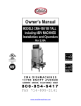
Procedure 5: CONNECTION FOR
HOT WATER SUPPLY
Water supply line must have capacity to supply 30.0
gallons per hour at 15-25 PSI flow pressure to the
dishwasher.
Model JP-24B/BF is equipped with an internal booster
heater tank ("B" model designation) to boost the
regularly available 140 degree F. hot water up to 180
degree F. for the required sanitizing final rinse.
Dishwasher will require a minimum 140 degree F. hot
water supply.
Model JP-24/F does not have an internal booster and
will require a minimum 180 degree F. hot water supply.
Model JP-24LT7F is a low-temperature chemical sanitizing machine and will require a 120 degree F. min. (factory recommended 140 F.) hot water supply.
INCOMING HOT WATER SERVICE CONNECTION
(SUPPLIED BY CUSTOMER) MUST BE A 1/2 INCH
PIPE SIZE MINIMUM WITH SHUT-OFF VALVE.
Procedure 5: CONNECTION FOR
HOT WATER SUPPLY
LINE
Steps:
1. Connect water supply line to dishwasher using soft
copper tubing or flexible copper tubing. Loop sufficient length of tubing at rear of machine so it can be moved for servicing.
2. Install 1/2'' flexible fill hose between service connection and dishwasher 1/2 "line strainer (female) behind lower kick panel.
Hot water service connection must have 1/2" male hose fitting.
FLUSH HOT WATER SUPPLY LINE FOR DEBRIS BEFORE CONNECTING TO DISHWASHER. DO NOT TAP SUPPLY
LINE FOR OTHER SERVICE — THIS WILL DROP THE REQUIRED FLOW PRESSURE FOR DISHWASHER FINAL
RINSE.
WATER FLOW PRESSURE REQUIREMENTS
The dishwasher requires 20 PSI +/-5 PSI flow pressure. Do not confuse static pressure with flow pressure.
Flow pressure is the pressure in the final rinse line when the rinse valve is open, and machine is rinsing. Static pressure is line
pressure with no water flowing, all valves and service closed.
Procedure 6: CHECKING FOR PROPER WATER LEVEL
Step:
1. Run machine through several cycles. The proper water level is reached when water touches the screen portion of the
dishwasher's basket strainer each cycle. If the water level is higher, install pressure reducing valve and adjust valve to 20
PSI until proper water level is achieved. Pressures above 25 PSI will cause rinse spray to fog or atomize. If water level is
lower than basket strainer, you must have low water pressure, check with plumber to see if pressure can be corrected.
WARNING: Dishwasher will not clean or sanitize ware properly without proper water pressure and temperature.
Procedure 7: INSTALLATION OF PRESSURE GAUGE
A pressure gauge is not supplied with the dishwasher. A petcock valve is provided in the incoming water line at the fill valve
for a pressure gauge. To verify proper water pressure, keep valve closed until reading the pressure, then close valve.
Procedure 8: ELECTRICAL REQUIREMENTS AND CONNECTIONS
IMPORTANT — PLEASE READ CAREFULLY — NOTE TO ELECTRICAL INSTALLER: THE RINSE HEATER RELAY HAS BEEN
TEMPORARILY DISABLED SO THAT THE MACHINE'S INTERNAL BOOSTER TANK CAN FILL WITH WATER BEFORE TURNING
ON THE HEATING ELEMENT. A QUALIFIED SERVICEMAN MUST RECONNECT THE WIRE (ORANGE/WHITE) TO THE RINSE
HEATER RELAY COIL (TAGGED) AFTER THREE CYCLES OF OPERATION AND THE WASH TANK IS FULL OF WATER. THE
CIRCUIT BREAKER FEEDING THE UNIT SHOULD BE TURNED OFF BEFORE DOING THIS.
WARNING:
ALL FIELD WIRING CONNECTIONS MUST CONFORM TO THE LOCAL AND NATIONAL ELECTRICAL CODES.
INSTALL PROPER CIRCUIT BREAKER, WIRE AND CONDUIT SIZE. THIS DISHWASHER MUST BE ADEQUATELY
AND SAFELY GROUNDED. INJURY OR DEATH MAY OCCUR FROM SHOCK IF MACHINE IS NOT PROPERLY
GROUNDED. PRIOR TO INSTALLATION, TEST THE ELECTRICAL SERVICE TO ASSURE THAT IT IS CORRECT
WITH THE SPECIFICATIONS ON THE MACHINE DATA PLATE.
All machines are factory pre-wired for one point connection to the dishwasher terminal block and ground lug. Model
JP-24LT/F will be supplied with a plug and cord factory installed to machine.
Steps:
1. Refer to dishwasher electrical data decal located on the right-side of machine for machine voltage and amperage load
and serial number.
2. IMPORTANT — PLEASE READ CAREFULLY:
BEFORE PROCEEDING TO CONNECT
POWER SUPPLY TO MACHINE, MAKE SURE THE
ORANGE/WHITE WIRE IS DISCONNECTED FROM
THE RINSE HEATER RELAY COIL. WIRE WILL BE
TAGGED AND MARKED.
3. REMOVE FRONT LOWER KICK PANEL BY
REMOVING TWO SCREWS AT THE BOTTOM CORNERS AND LIFT UP AND AWAY. CHECK TO SEE
THAT ORANGE/WHITE WIRE IS DISCONNECTED, IF
NOT, DISCONNECT.
4. SET KICK PANEL BACK INTO PLACE — DON'T
FASTEN DOWN WITH SCREWS.
5. MODEL JP-24LT/F: Route plug end of cord to mating
receptacle (provided by installer) and insert squarely and
securely. Other end of plug is factory installed to machine
terminal block and is secured in place with a cord grip for
strain relief.
IMPORTANT — PLEASE READ CAREFULLY — for
personal safety, this dishwasher must be properly
grounded. The power cord of this dishwasher (JP24LT) is equipped with a three-prong grounding plug
which mates with a standard three-prong
grounding wall receptacle. Have the wall receptacle
and circuit checked by a qualified electrician to make
sure the receptacle is properly grounded. DO NOT, UNDER ANY CIRCUMSTANCES, CUT OR REMOVE THE THIRD
(GROUND PRONG FROM THE POWER CORD.
6. MODELS JP-24/F, JP-24B/F: Install conduit from rear of machine to hole directly above machine's terminal block. 7.
Route power wires, L1, L2 and Ground to terminal block.
8. Install power wires, L1,1-2 and Ground to appropriate terminals marked L1, L2 at terminal block. Install ground wire into
grounding lug provided. NOTE: It is also recommended that "DE-OX"or similar antioxidation agent be used on all incom
ing power connections.
WARNING: INSURE ALL WIRING CONNECTIONS TO TERMINAL BLOCK AND GROUND LUG ARE PROPERLY
TIGHTENED AND TORQUED ACCORDINGLY.
Procedure 9: CHECK FOR PROPER VOLTAGE
Steps:
1 Apply power to dishwasher. WARNING: CHECK INCOMING POWER AT POWER BLOCK FOR PROPER VOLTAGE
PER MACHINE'S ELECTRICAL DATA DECAL. IF APPLICABLE, CHECK VOLTAGE AT L1 AND L2 TO GROUND
INDIVI-DUALLY TO INSURE NEITHER IS CONNECTED TO A HIGH OR WILD LEG.
2. Turn off power switch on machine and at service breaker. Mark breaker for dishwasher and advise proper personnel
CAUTION: DO NOT APPLY POWER TO MACHINE OR OPERATE MACHINE AT THIS TIME UNLESS PLUMBING
(DRAIN) AND WATER SUPPLY CONNECTIONS HAVE BEEN MADE.
Procedure 10: TO FILL DISHWASHER WITH WATER
Steps:
1. Open incoming water shut-off valve to machine and place the "ON/FILL" switch to the "ON" position. Machine shout ^
up with water.
2. Open and close door to start a dishwashing cycle. Run machine through several complete wash and rinse cycles.
3. When machine's wash tank is full of water up to screen portion of basket strainer, proceed as follows:
fill
4. IMPORTANT — PLEASE READ CAREFULLY — NOTE TO ELECTRICAL INSTALLER: THE RINSE HEATER RELAY HAS BEEN
TEMPORARILY DISABLED SO THAT THE MACHINE'S INTERNAL BOOSTER TANK CAN FILL WITH WATER BEFORE TURNING ON
THE HEATING ELEMENT. A QUALIFIED SERVICEMAN MUST RECONNECT THE WIRE (ORANGE/WHITE) TO THE RINSE HEATER
RELAY COIL (TAGGED) AFTER THREE CYCLES OF OPERATION AND THE WASH TANK IS PULL OF WATER. THE CIRCUIT
BREAKER FEEDING THE UNIT SHOULD BE TURNED OFF.) BEFORE DOING THIS.
Procedure 11: TO INSTALL CHEMICAL DISPENSING EQUIPMENT
The JP-24 series dishwasher is not supplied with dispenser pumps for detergent, rinse additive or sanitizer (JP-24LT/F).
Low -temperature chemical sanitizing Model JP-24LT/F requires a minimum of 50 PPM of 5.25% sodium hypochlorite (liquid bleach) be injected in the final
rinse line during the rinse. Do not operate dishwasher as a low -temperature chemical sanitizing machine without a properly installed, N.S.F. recognized
chemical dispenser. Contact an authorized detergent representative for information about a chemical dispenser.
The dishwasher is a DUMP-AND-FILL type machine that dumps (drains) the wash water after each washing cycle, water added from the fresh water final rinse
is used for the next washing cycle.
Detergent Recommendations and Rinse Additives: We suggest that you contact your local Detergent Specialist for the correct detergent and rinse
additives for your area. Dump the detergent on the pan strainer. This may have to be increased or decreased to obtain satisfactory results.
VERY IMPORTANT: Do not use a domestic type detergent in this machine at any time. This type of detergent may damage and/or obstruct pump operation
and may cause corrosion to tank.
CAUTION: WHEN USING OR WORKING WITH LIQUID DETERGENT AND SANITIZER (LIQUID BLEACH) USE
CAUTION AS IT CAN IRRITATE THE SKIN.
Step 1: DISPENSING EQUIPMENT ELECTRICAL CONNECTION
Power and signal source for detergent, rinse additive and sanitizer (JP-24LT/F) dispensing equipment are provided as follows:
DETERGENT SIGNAL — White/Red wire, "L1" signal (line voltage) for detergent dispensing. Detergent dispenses during rinse
cycle.
DISPENSER POWER — Red wire, "L2" return (line voltage).
DISPENSER POWER — Green/White wire, "L1" power (line voltage) during dishwashing cycle.
RINSE
AGENT/ — Blue wire, "L1" signal (line voltage) during rinse cycle for dispensing rinse agent and sanitized (JPSANITIZER SIGNAL
24LT/F) into final rinse line during rinse.
DISPENSER MAXIMUM AMPERAGE LOAD: LINE VOLTAGE
MAXIMUM.
0.5KVA MAX. FUSE-TYPE SAG "SLO-BLO" 2.5A
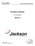
Procedure 11:
Step 3 and 4
TIMER ADJUSTMENT FOR DETERGENT
CONCENTRATION
The amount of detergent may need to be increased or
decreased depending on water quality and type of
detergent. It is factory set to dispense 15 miililiters of
detergent into the wash water during the rinse cycle.
Consult your detergent representative for adjustment.
Step 2: LIQUID DETERGENT DISPENSING POINT
Liquid detergent will be dispensed into machine from
factory supplied hole at rear wall of machine above
basket strainer. Remove factory installed plug and install
injection fitting for injecting detergent.
Step 3: RINSE ADDITIVE INJECTION — FINAL RINSE
LINE
.Power and signal source for injecting rinse additive into
the final rinse line manifold may be obtained by using a
pressure switch in the final rinse line or by connecting in
parallel to the rinse/fill solenoid blue wire.
Step 4: LOW TEMPERATURE JP-24LT/F SANITIZER INJECTION
WARNING: Low-temperature chemical sanitizing Model JP-24LT/F requires a minimum of 50 PPM of 5.25% sodium
hypochlorite (liquid bleach) be injected in the final rinse line during the rinse. Do not operate dishwasher as a lowtemperature chemical sanitizing machine without a properly installed, N.S.F. recognized chemical dispenser. Con- ct
an authorized detergent representative for information about a dispenser.
Follow the same procedure outlined for rinse additive injection to inject sanitizer during the final rinse.
WARNING: DO NOT PRE-MIX RINSE ADDITIVE AND SODIUM HYPOCHLORITE (LIQUID BLEACH). CERTAIN MATERIAL SUCH AS
SILVER PLATE, ALUMINUM AND PEWTER ARE ATTACHED BY SODIUM HYPOCHLORITE (LIQUID BLEACH).
DISHWASHER OPERATING INSTRUCTIONS
INITIAL START-UP:
1. Open door and install basket strainer into wash tank.
2. Install rinse spray arm assembly into fitting at upper wash chamber.
3. Install wash spray arm assembly into fitting at lower wash chamber.
4. Install lower rinse spray arm assembly feed pipe fitting.
5. Install detergent, rinse additive and sanitizer (JP-24LT/F Only) pickup (suction) tube into chemical bottle.
TO FILL THE UNIT AT START OF DAY
6. Close door and place power switch in On/Fill position and place Cycle switch in Auto position. Red power indicator light will
light to indicate machine has power turned on and the green light will come on to indicate that the machine is automatically filling with water. Proper water level will be achieved when water touches the bottom of basket strainer.
NOTE: CYCLE SWITCH MUST BE IN THE AUTO POSITION TO PILL MACHINE. MACHINE WILL NOT FILL IN THE MANUAL
POSITION AND WOULD CAUSE PUMP MOTOR TO RUN WITHOUT WATER WHICH CAN DAMAGE PUMP SEAL.
7. After the wash tank is full of water, the green fill light will go out. Open the door, the amber cycle light will go out to indicate that the
machine is reset for another dishwashing cycle.
REQUIRED OPERATING TEMPERATURES
8. Close the door and the machine will automatically go through the complete wash, drain and rinse cycles. The amber cycle
light will remain on during the complete dishwashing cycle and go out at the completion of the cycle. NOTE: Initially, at
start-up, run machine thru several cycles to reach operating temperatures of 150 degree F. wash and 180 degree F.
rinse.
Detergent, rinse additive and sanitizer (JP-24LT/F Only) will dispense automatically during dishwashing cycle.
9. When dishwasher has reached operating temperatures, place rack of soiled ware into machine and close door.
STANDBY MODE OF OPERATION
10. Placing the Cycle switch to the center "Off" position will allow the door to be opened and closed without starting an
automatic cycle. Machine will still maintain proper temperatures in this position.
DOOR SAFETY SWITCH OPERATION
11. If door is opened during a dishwashing cycle, machine will stop the cycle until door is closed. When door is closed, cycle
I, will resume where it was stopped.
TO DRAIN THE MACHINE AT END OF DAY/MEALTIME
12. The dishwasher Cycle switch must be in the Auto position in order to drain machine. Machine will not drain in the Manual
mode.
a. Close the door and start a dishwashing cycle without a rack in the machine.
b. Once the cycle has started and the amber cycle light is on, push the Power switch from the On/Fill position to the
Off/Drain position. The machine will finish the wash cycle and then drain.
13. Daily or as needed: Clean strainer, wash arms and rinse arms and delime machine.
WARNING: DO NOT OPERATE WASH PUMP WITHOUT WATER IN THE WASH TANK. THIS WILL CAUSE DAMAGE TO
PUMP SEAL.
MANUAL WASH
14. Place Cycle switch in the Manual Wash position. In this position, machine will wash indefinitely until switch is placed in
Center Off or Auto Cycle position. Detergent will be dispensed in this mode.
DELIMING OF MACHINE
15. Follow Steps to drain machine.
1. Remove detergent, rinse additive and sanitizer (Model JP-24LT/F) pickup (suction) tubes from chemical bottles or
disable dispenser pumps by turning off power to pumps.
2. Place Power switch to On/Fill position then close and latch door. Allow machine to complete a fill cycle.
3. Open the door and dispense delimer (follow manufacturer's instructions on product label) into basket strainer. Place
Cycle switch in Manual Wash position.
4. Close and latch the door. The machine will begin to run continuously. Allow the machine to run and delime for 10-15
minutes.
5. Place the Cycle switch to the Auto position.
6. Run several normal cycles to completely flush residual deilming solution from the machine.
CAUTION: NEVER LEAVE DELIMER SOLUTION IN THE MACHINE OVERNIGHT OR FOR LONG PERIODS OF TIME
(OVER ONE HOUR).