1
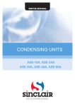
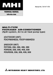
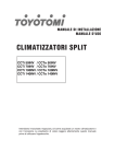
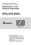
Air Conditioner
Service Manual
2
MODEL:
AC-CF40CM
Model No.: AC-CF40CM
Version: 1.0
3
CONTENTS
PRODUCT FEATURES........................................................................................................................... 4
TECHNICAL SPECIFICATION.............................................................................................................. 6
NOISE LEVEL......................................................................................................................................... 8
VELOCITY AND TEMPERATURE DISTRIBUTION........................................................................... 9
OPERATION RANGE ........................................................................................................................... 11
CAPACITY TABLE ............................................................................................................................... 12
REFRIGERATION CYCLE DIAGRAM............................................................................................... 13
ELECTRIC CONTROL FUNCTION .................................................................................................... 14
TROUBLE SHOOTING ........................................................................................................................ 19
WIRING DIAGRAM ............................................................................................................................. 22
INSTALLATION.................................................................................................................................... 24
SERVICING AND MAINTENANCE ................................................................................................... 39
EXPLODED VIEW................................................................................................................................ 41
PART LIST ............................................................................................................................................. 43
Model No.: AC-CF40CM
Version: 1.0
4
PRODUCT FEATURES
1.
Convenient installation
a. The ceiling type can be easily installed into a corner of the ceiling even if the ceiling is very
narrow.
b. It is especially useful when installation of an air conditioner in the center of the ceiling is
impossible due to a structure such as lighting.
Floor & ceiling type
2.
Double auto swing and wide angle air flow
a. Air flow directional control minimizes the air resistance and produces wilder air flow to
vertical direction
b. The range of horizontal air discharge is widened which secures wider air flow distribution to
provide more comfortable air circulation no matter where the unit is set up.
Model No.: AC-CF40CM
Version: 1.0
5
3.
Water proof by utilizing the absorbing plastic film on water collector
4.
Low noise level plus compact size
a. Shape of the blades has been improved to prevent noise caused by turbulence
Model No.: AC-CF40CM
Version: 1.0
6
TECHNICAL SPECIFICATION
Power supply
Cooling
Capacity
Capacity
Input
Rated current
EER
Moisture Removal
Max input consumption
Max current
Starting current
Type
Capacitor
Input
Rated current (RLA)
Compressor
Locked rotor Amp (LRA)
Thermal protector
Capacitor
Refrigerator
Input
Indoor fan motor
Capacitor
Speed (hi /lo)
Number of rows
Tube pitch (a) x row pitch (b)
Fin spacing
Indoor coil
Fin type (code)
Tube outside dia and type
Coil length x height x width
Number of circuits
Indoor air flow (Hi /Lo)
Indoor noise level (Hi /Lo)
Dimension (W * H * D)
Indoor unit
Packing (W * H * D)
Net /Gross weight
Input
Outdoor fan motor
Capacitor
Speed
Number of rows
Tube pitch (a) x row pitch (b)
Fin spacing
Outdoor coil
Fin type (code)
Tube outside dia and type
Coil length x height x width
Number od circuit
Outdoor air flow
Outdoor noise level
Dimension (W * H * D)
Outdoor unit
Packing (W * H * D)
Net Gross weight
Model No.: AC-CF40CM
Version: 1.0
Ph-V-Hz
Btu/h
kW
W
A
Btu/W.h
L/h
W
A
A
Btu/h
W
A
A
uF
ml
W
uF
R/min
mm
mm
mm
mm
M3 /h
dB(A)
mm
mm
kg
W
uF
R/min
mm
mm
mm
mm
M3/ h
dB (A)
mm
mm
kg
220-240V, 50Hz
36000
10.5
4100
18.6
8.8
3.6
6150
28
58
Scroll
39602
4000
17.3
50
Internal type
60uF /450V
DAPHN-E FV68S 1697
130
3.5
1250 /940
3
25.4 x 22
1.7
Hydrophilic aluminium
Φ9.53, innergroove tube
905* 203* 66
5
1400/ 1200
49/ 43
1860 * 600 * 220
1984 * 730 * 370
32/ 40
290
10
850
2
25.4 x 22
1.7
Unhydrophilic aluminium
Φ9.53, bare tube
715 x 1220 x 44
4
6000
62
990 x 960 x 360
1120 x 1090 x 435
99/ 104
7
Refrigerant type R407C
Design pressure
Liquid side
Refrigerant piping
Max. refrigerant pipe length
Max. difference in level
Connection wiring
Plug type
Controller
Operation temp
Ambient temp
Application area
Qty per 20’ /40’ 40HQ
g
MPa
mm
(inch)
m
m
o
C
C
m2
Pc
o
2700g
2.8 /1.2
Φ19 (3/4’) Φ12.7 (1/2”)
25
10
NO
NO
Remote
17 ~ 30
18 ~ 45
60-85
28 /66 /76
Note:
1. Nominal cooling capacities are based on the following conditions:
a. Indoor temp: 27oCDB, 19oCWB
b. Outdoor temp: 35oCDB
2. Nominal heating capacities are based on the following conditions:
a. Indoor temp: 20oCDB
b. Outdoor temp: 7oCDB, 6oCWB
3. Actual noise level may differ, depending on the room structure, etc. since these noise values are from
an anechoic room.
Model No.: AC-CF40CM
Version: 1.0
8
NOISE LEVEL
Ceiling
Floor
High airflow
Low airflow
36000btu/h
Sound pressure level dB(0dB=0.0002µ bar)
Sound pressure level dB(0dB=0.0002µ bar)
1.30000btu/h
Audibility limits of
continuous white
sound
Octave band center frequency(Hz)
Ceiling
Model No.: AC-CF40CM
Version: 1.0
Audibility limits of
continuous white
sound
Octave band center frequency(Hz)
Floor
9
VELOCITY AND TEMPERATURE DISTRIBUTION
Discharge angle 60° (CEILING)
Airflow velocity
Temperature
Model No.: AC-CF40CM
Version: 1.0
10
Discharge angle 60°(FLOOR)
Airflow velocity
Temperature
Model No.: AC-CF40CM
Version: 1.0
11
OPERATION RANGE
Ensure the operating temperature is in allowable range.
Cooling only
Cool i ng
Ambi ent
emp. ( ° C)
52
45
STD
35
17
-7
17
24
30
I ndoor t emp. ( ° C)
Heat pump
Heat i ng
Cool i ng
17
emp. ( ° C)
STD
STD
35
17
Ambi ent
6
Ambi ent
emp. ( ° C)
52
45
-7
-7
17
24
30
I ndoor t emp. ( ° C)
Model No.: AC-CF40CM
Version: 1.0
17
24
30
I ndoor t emp. ( ° C)
12
CAPACITY TABLE
COOLING
Indoor
Conditions
21ºC D
15ºC W
24ºC D
17ºC W
27ºC D
19ºC W
32ºC D
23ºC W
OUTDOOR TEMPERATURE DRY
Total capacity kW
Sensitive capacity
kW
Input kW.
Total capacity kW
Sensitive capacity
kW
Input kW.
Total capacity kW
Sensitive capacity
kW
Input kW.
Total capacity kW
Sensitive capacity
kW
Input kW.
Model No.: AC-CF40CM
Version: 1.0
21ºC
25ºC
30ºC
35ºC
40ºC
45ºC
50ºC
10.19
9.75
9.39
8.86
8.51
8.24
7.98
8.15
7.80
7.51
7.09
6.81
6.59
6.38
2.58
11.16
2.95
10.68
3.32
10.29
3.69
9.71
4.06
9.32
4.43
9.03
4.80
8.74
8.93
8.54
8.23
7.76
7.45
7.22
6.99
2.73
12.13
3.12
11.61
3.51
11.18
3.90
10.55
4.28
10.13
4.67
9.81
5.06
9.50
9.71
9.28
8.95
8.44
8.10
7.85
7.60
2.87
13.95
3.28
13.35
3.69
12.86
4.10
12.13
4.51
11.65
4.92
11.28
5.33
10.92
13.89
13.28
12.80
12.08
11.59
11.23
10.87
11.11
10.63
10.24
9.66
9.27
8.98
8.69
13
REFRIGERATION CYCLE DIAGRAM
Cooling only
Outdoor unit
Indoor unit
Valve
Sensor of room temp.
Heat exchanger
Heat exchanger
Sensor of heat
exchanger temp.
Compressor
Valve
Model No.: AC-CF40CM
Version: 1.0
Capillary
14
ELECTRIC CONTROL FUNCTIONS
Performance Index
No.
1
2
3
Item
Applicable Voltage Range
A/C Frequency
Working environment temperature
Index
185-253V~, 342-418V~
50Hz
-5°C- +43°C
Main Parts Introduction
1.
Indoor Fan
a. High speed and low speed.
b. Breeze speed for anti-cold air.
2.
Outdoor Fan
a. High speed and low speed.
b. Remark: some model just have one speed.
3.
Buzzer
a. It will buzz when its driving port in the main chip outputs high level.
b. It will buzz once when the main frame receives remote start-up signal.
c. It will buzz once for 1 second when receiving turn-off signal.
d. It will buzz for 0.5 second once receiving other signal.
4.
Indicator
a. There are 4 indicators: operating indicator, timer indicator, water level warning indicator,
defrosting indicator and pre-heating indicator (wind-delivery indicator for cooling-only A/C).
b. LED indicates errors when protection is in effective.
5.
Four-way Valve
It is controlled by relays.
Operation Modes and Functions
1.
Manual Operation
a. The manual operation mode is controlled through “manual” pad in the wind in-take grid,
including such two modes as manual action and manual cooling. Push the manual pad for each
switchover, the order for which is shown below:
REMOTE CONTROL
Model No.: AC-CF40CM
Version: 1.0
MANUAL ACTION
MANUAL COOLING
15
2.
b.
Manual Cooling
i.
Under this mode, no remote control signal will be received.
ii.
The compressor is started up unconditionally and the rotating speed of indoor and
outdoor fans is set to be in high and forced cooling operation.
iii.
Under this mode, the buzzer will buzz twice with each lasting 0.5 second at 0.5
interval. During the first 30 minutes of unconditional forced cooling operation, the
operation indicator will blink at 0.5Hz. In the process of switchover to manual action
mode, the buzzer buzzes for 0.5 second and the indicator is illuminated.
iv.
Under this mode, the corresponding protections are in effective (3- minute delayed
start-up, over current, outdoor protection and evaporator low temperature protection.).
Corresponding protection will act once any protection is in active. Push “manual”
pad once to end this mode and enter the remote control pending status. The buzzer
will buzz for 1 second and the indicator turn off.
c.
Manual Action
i.
Under this mode, the remote signal will be received and corresponding actions will
be taken accordingly upon the receipt of the remote signal.
ii.
On entering this mode, the buzzer will buzz for 0.5 second and the indicator on.
iii.
The system will operate under the auto mode whose temperature is set to be 24°C
and at the same time, the wind grille will swing automatically.
iv.
Under this mode, corresponding protections are in effective.
v.
Push “ manual” pad to end this mode and switch over to manual cooling mode.
Heating Mode
a. Four-way valve opens at once, while defrosting process closes.
b. Condition for the compressor action: (Ts = set temperature, Ta = room temperature)
Condition
Room temp. up
Room temp. down
c.
Ta> Ts+4℃
Ta <Ts+4℃
Ta < Ts+3℃
Ta >Ts+3℃
Compressor
Off
On
On
Off
Outdoor fan
Off
On
On
Off
Indoor Fan Action
i.
Fan speed among high/low/auto,(anti-cold air function takes priority).
ii.
Anti-cold air:
Switchover between fan speed and fine tune can be set according to temperature of
evaporator pipe.
Indoor
exchanger
temp. up
Indoor
exchanger
temp.
down
Condition (T= Indoor
exchanger temp.)
T<25°C
25°C <T<32°C
Indoor
fan speed
Off
Breeze
T>32°C
Setting
fan speed
Setting
fan speed
T> 30°C
15°C <T<30°C
T<15°C
Breeze
Off
During anti-cold air period, if indoor fan is shut down, then pre-heating/defrosting
lamp is on. Once indoor fan starts, pre-heating/defrosting lamp will be off.
Model No.: AC-CF40CM
Version: 1.0
16
iii.
Auto fan of indoor fan under heating mode.
Room temp. up
Room temp. down
3.
Condition (T =Indoor Temp.- Setting
Temp.)
T <3°C
T >3°C
T > 1°C
T <1°C
Indoor fan speed
High
Low
Low
High
Defrost (only available to heating mode)
a. The defrosting of 1~3HP, 4HP(1N) is processed by indoor control board.
i.
Defrosting Conditions
Low temperature defrosting condition:
Accumulated operating time when temperature of outdoor heat exchanger Coil T3 is
below -2°C reaches up to over 40 minutes.
High temperature defrosting condition:
Under high temperature protection of evaporator, the time when outdoor fan is shut
down but compressor is not has been accumulated for up to 90 minutes. It is
considered that defrosting is performed when either 3.3.1.1 or 3.3.1.2 is met.
ii.
Defrosting Action
Four-way valve and outdoor fan are shut down. Indoor fan operates according to
anti-cold air function. Compressor keeps on continuously.
iii.
Ending Of Defrosting Condition
It is considered that defrosting condition is ended when any of the conditions is met:
Operating current of compressor reaches 1.5Ie.
Time of defrosting reaches 10 minutes.
Temperature of outdoor coil T3 is up to 20°C.
iv.
Ending Action of Defrost
Outdoor fan and four-way valve are open.
Compressor keeps on continuously.
Indoor fan acts according to anti-cold air function.
Defrosting/pre-heating lamp continues to be on until indoor fan starts up.
b.
The defrosting of 4~7HP(3N) is processed by outdoor control board.
i.
Defrosting Conditions (any of the following conditions is met)
Under indoor pipe high temperature protection in heating mode, accumulated
operating time is up to 90 minutes (if outdoor fan is off and compressor are cut
down, time again.)
When T4≥-8℃, 1min, process the normal defrost mode: compressor operates
continue 40 minute, the accumulated time up to 40 minutes when pipe
temperature sensor T3≤-2℃ (if compressor is off, time again); when defrosting
ends, check T4 again.
ii.
Defrosting Action
When defrosting, the outdoor four-way valve is power off, defrosting valve is
power on, outdoor fan is off, compressor operate continue, indoor fan operates
according to anti-cold air condition in heating mode. If indoor fan is to be off,
cut down the electric auxiliary heater and after 15 seconds cut down indoor fan.
iii.
Ending Action of Defrost (any of the following conditions is met)
Time of defrosting reaches 10 minutes.
Temperature of outdoor coil T3 is up to 20°C
iv.
Ending Action of Defrost
Operate in normal heating mode. After defrost stops, indoor fan starts to operate
according to anti-cold air condition.
Model No.: AC-CF40CM
Version: 1.0
17
4.
Cooling Mode
a. Four-way valve is closed.
b. Conditions for the compressor and outdoor fan action (Ts = set temperature, Ta=room
temperature)
Room temp. up
Room temp. down
c.
Condition
Ta > Ts+1
Ta <Ts+1
Ta > Ts
Ta <Ts
Compressor
On
Off
On
Off
Outdoor fan
On
Off
On
Off
Action of Indoor Fan
i.
HIGH/LOW/AUTO fan can be switched over for your comfort.
ii.
Auto fan under cooling mode.
Temp. up
Temp. down
Condition (T=Indoor Temp.-Setting
Temp.)
T<4°C
T>4°C
T> 1°C
T<1°C
Indoor fan speed
Low
High
High
Low
5.
Dehumidifying Mode
a. Dehumidifying mode is the cooling operation, under which the indoor fan is high and outdoor
fan is low.
b. Protective condition is active.
6.
Auto Mode
a. Under auto mode, the indoor fan is set to be auto (refer to auto fan under cooling, heating).
b.
When entering auto mode, the heating, fan only or cooling operation will be automatically
chosen according to the room temperature Ta and the set temperature Ts.
i.
When Ta < Ts -1°c, it performs the heating operation with a set temperature of Ts
-1°c (refer to the heating mode). However the cool only model will be in low fan.
ii.
When Ts +2°c ≥ Ta ≥ Ts -1°c, control according to cooling auto fan with a set
temperature of 23°c.
iii.
c.
d.
7.
When Ta > Ts +2°c, it performs the cooling operation with a set temperature of Ts
(refer to the cooling mode).
After one mode is chosen, if the condition Ta > Ts+1°c or Ta < Ts - 1°c lasts for 15 minutes,
meanwhile the compressor doesn't start up within consecutive 15 minutes, the operation mode
will be re-chosen according to the Ta and Ts.
Protective condition is active.
Fan Only Mode
a. Under this mode, four-way valve, compressor and outdoor fan are shut down.
b. High/Low/Auto fan can be switched over through manual control. Auto fan will be controlled
in line with cooling auto fan with temperature set to be 23°C.
c. After entering fan mode, the operating indicator is on. If the model is cooling only mode, fan
indicator is on at the same time.
Model No.: AC-CF40CM
Version: 1.0
18
Other Functions
1. LED Display
Operation lamp, timer lamp, defrosting/pre-heating lamp, and water level alarm lamp.
a. Operation Lamp
When the operation is recovering, it will blink at 1 Hz.
After the unit is on, the lamp will keep on.
After the unit is off, the lamp will be off.
When the unit is switched over from manual cooling to remote control, the lamp will be off.
b. Timer Lamp
During timer operation, it will be on.
c. Defrosting/Pre-Heating Lamp
When heat pump model performs defrosting or anti-cold air, it will be on.
2.
Timer
Refer to remote controller manual for detail operation.
Note: The timer is valid for one operation of the A/C.
Model No.: AC-CF40CM
Version: 1.0
19
TROUBLE SHOOTING
1.
Protective Function
a. 3-minute delay for the compressor start-up.
At the beginning of energizing or after the stop of the compressor, 3-minute delay will be
needed to start the compressor.
When switchover between cooling/heating mode, the compressor stops automatically.
b.
Compressor current overload protection
i.
3HP and 4HP(1N) compressor current examination and action
current
3 seconds later, the compressor / outdoor fan close down
I3
5 minutes later, the compressor / outdoor fan close
down
I2
I1
Recover
restart the outdoor fan
(works only when heating)
Remark :Ie: rating current; I1:1.3 time Ie; I2:1.5 time Ie; I3:2.0 time Ie.
The compressor and outdoor fan closed for protection purpose will restart after 3
minutes.
During the protection, the indoor fan continues working in a set speed, while the
anti-cold air function when heating and the compressor will be 3 minutes
ii.
iii.
delayed to shut down for protection.
When there are 4 times compressor protection within one hour, the A/C will be
shut down, meanwhile the operation light and timer light will be turned on, the
defrosting light flashes in a frequency of 0.5Hz. This situation will be
recovered only when power is switched off.
If AC don’t check the compressor current through electric control system, then use
compressor self current protection.
4HP(3N) and 5HP compressor current is checked by outdoor main board. The
protection principle is as following:
In any case, after the compressor starts, if
Only in heating mode, when current is higher than 1.5Ie, then outdoor fan will
shut off. When compressor current is less than 1.3Ie, then restart outdoor fan and
recover operation.
When current is higher than 1.5Ie and time is up to 20seconds, compressor and
outdoor fan will shut down. At the same time, cut down outdoor protection
communication wiring, protection malfunction will be indicated by indoor unit
and 3minutes later restart compressor.
Model No.: AC-CF40CM
Version: 1.0
20
c.
Evaporator protection against high temperature(heating mode)
Only available to heating mode, including heating mode, heating operation under auto mode.
※ Note: During protection, the indoor fan continues operating at a setting speed, while the anti-cold
air function of heating and the compressor will be 3 minute delayed to shut down for protection.
d.
Evaporator Protection against low temperature (cooling mode)
i.
When the evaporator pipe temperature ≤ 3°c and this lasts for 3 minutes, the
compressor and outdoor fan will be shut off.
ii.
iii.
e.
When the evaporator pipe temperature ≥ 7°c, it recovers.
The restart of the compressor shall execute the delay protection.
Anti-cold air protection
Only available to heating mode, including heating mode, heating operation under auto mode.
f.
Condenser high temperature protection
i.
Only available to cooling (incl. cooling mode, cooling operation under auto mode)
and dehumidifying mode.
ii.
g.
Delay protection should be performed when the compressor restarts.
Outdoor protection
Only 3HP has outdoor protection function.
Model No.: AC-CF40CM
Version: 1.0
21
2.
Self-diagnosis
a.
Indoor unit
No.
1
Type
Protection
Contents
Over current protection of the
compressor occurs 4 times in 1h
2
Protection
3
Error
4
Error
5
Error
6
Error
Outdoor protection (absent
phrase, phrase sequence and
temperature protection)
Room temperature sensor
checking channel is abnormal
Evaporator sensor checking
channel is abnormal
Condenser sensor checking
channel is abnormal
Temperature fuse is
melt(reserved)
b.
LED Flashing
Lamps of operation,
timer, defrosting (only
fan) flashing
simultaneously at 5Hz.
All lamps flashing at
5Hz
Timer lamp flashing at
5Hz
Operation lamp flashing
at 5Hz
Defrosting lamp flashing
at 5Hz
Operation lamp and
timer lamp flashing at
5Hz
Remark
Whole unit is shut
down. It cannot
recover unless
power is cut off
Recover
automatically
after errors are
eliminated (For
T3 malfunction of
5HP, can’t recover
automatically)
LEDs for the indication of outdoor trouble (3 ~ 3.5HP, 3 phase)
LED3
Contents
Normal
Ok
Off
Off
On
Protection
Phase sequence error
On
Off
On
Protection
Overload of current
Off
On
On
Protection
Lack of phase
On
On
On
Protection
Protection of pressure
On
On
On
c.
LED1
LED2
Type
LEDs for the indication of outdoor trouble (4 ~ 7 HP, 3 phase)
Type
Protection
Protection
Protection
Protection
Protection
Protection
Protection
Contents
Phase sequence
Lack of phase
Protection of pressure
Overload of current
Open-circuit and short-circuit trouble of T3
Open-circuit and short-circuit trouble of T4
High temperature protection of condenser
Model No.: AC-CF40CM
Version: 1.0
LED1
Flash
Flash
Flash
Off
Off
Off
Flash
LED2
Off
Off
Flash
Off
Flash
Flash
Flash
LED3
Off
Off
Off
Flash
Flash
Off
Flash
22
WIRING DIAGRAM
Indoor Unit
Model No.: AC-CF40CM
Version: 1.0
23
Outdoor Unit
Model No.: AC-CF40CM
Version: 1.0
24
INSTALLATION
1.
Installation of indoor unit
a. Wall Mounting Installation :
Please use the level indicator when install the unit on the floor by wall mounting.
Keep the unit perpendicular to the floor.
Use inlay screw blot or flaring screw bolt to install.
Inlay Screw Bolts
Inlay Screw Bolts
b. Ceiling Installation :
Overhang the indoor unit onto the hanging screw bolts with block.
Position the indoor unit in a flat level by using the level indicator, unless it may cause leakage.
Screw nut
Washer
Hanging
screw bolt
c.
Overhang part
Dimension
Capacity (Btu/ h)
1800Btu/h
2400-30000Btu/h
30000-36000Btu/h
48000-60000Btu/h
Model No.: AC-CF40CM
Version: 1.0
A
980
1200
1200
1860
B
864
1084
1084
1744
D
12.7
16
19
19
E
6.35
9.53
12.7
12.7
25
Chart for wall mounting installation
A
237
220
600
D. Connecting point of
refrigerant pipe
(D. gas side)
Drain point
E. Connecting point of
refrigerant pipe
(E. Liquid side)
B
350
Model No.: AC-CF40CM
Version: 1.0
26
Chart for Ceiling Installation
236
A
350
600
D. Connecting point of
refrigerant pipe
(D.gas side)
B
Drain point
E. Connecting point of
refrigerant pipe
>20
(E. Liquid side)
2.
Install outdoor unit
a.
Caution
i.
Keep this unit away from direct radiation of the sun or other heaters. If unavoidable,
please cover it with a shelter.
ii.
In places near coast or with a high attitude where the wind is strong, please install the
outdoor unit against the wall to ensure normal performance.
iii.
Use a baffle when necessary.
iv.
In the case of extremely strong wind, please prevent the air from flowing backwards
into the outdoor unit. (Refer to chart 10).
v.
Locate the outdoor unit as close to the indoor unit as possible.
vi.
The minimum distance between the outdoor unit and obstacles described in the
installation chart does not mean that the same is applicable to the situation of an
airtight. Leave open two of three directions A, B, and C.
Model No.: AC-CF40CM
Version: 1.0
27
b. Necessary room for installation and maintenance (Refer to chart 11)
Remove the obstacles nearby to prevent the performance from being impeded by too little of
air circulation. Leave open two of the three direction (A, B, and C).
c.
3.
Moving and installing
i.
Since the gravity center of this unit is not at its physical center, be careful when
lifting it with a sling.
ii.
Never hold the air-in of the outdoor unit to prevent it from deforming.
iii.
Do not touch the fan with hands or other objects.
iv.
Do not lean it more than 45o and do not lay it sidelong.
v.
Fasten the feet of this unit with bolts firmly to prevent it from collapsing in case of
earthquake or strong wind.
vi.
Make concrete foundation. (Refer to chart 12).
Refrigerant pipe connecting
Check whether the height drop between the indoor unit and outdoor unit. The length of
refrigerant pipe and the number of the bends meet the following requirement:
The max height drop …10m
(If the height drop is more that 10m, the outdoor unit should put above the indoor unit).
The length of refrigerant pipe …less than 30m
The number of bends …less than 10m
Model No.: AC-CF40CM
Version: 1.0
28
a.
Piping connection
i.
Measure the necessary length of the connecting pipe, and make it by the following
way.
Connect the indoor unit at first, then the outdoor unit.
Bend the tubing in proper way. Do not harm them.
CAUTIONS
Daub the surfaces of the flare pipe and the joint nuts with frozen oil, and wrench it for 3~4
rounds with hands before fasten the flare nuts.
Be sure to use two wrenches simultaneously when you connect or disconnect the pipes.
Tubing size
6.35
9.52
12.7
16
19
Torque
1420~1720N.cm(144~176kgf.cm)
3270~3990N.cm(333~407kgf.cm)
4950~6030N.cm(504~616kgf.cm)
6180~7540N.cm(630~770kgf.cm)
9720~11860N.cm(990~12106kgf.cm)
The stop value of the outdoor unit should be closed absolutely (as original state). Every time
you connect it, first loosen the nuts at the part of stop value, then connect the flare pipe
immediately (in 5 minutes). If the nuts have been loosened for a long time, dusts and other
impurities may enter the pipe system and may cause malfunction later. So please expel the air
out of the pipe with refrigerant before connection.
Expel the air after connecting the refrigerant pipe with the indoor unit and the outdoor unit.
Then fasten the nuts at the repair-points.
ii.
Locate The Pipe
Drill a hole in the wall (suitable just for the size of the wall conduit), then set on
the fittings such as the wall conduit and its cover.
Bind the connecting pipe and the cables together tightly with binding tapes. Do
not let air in, which will cause water leakage by condensation.
Pass the bound connecting pipe through the wall conduit from outside. Be
careful of the pipe allocation to do no damage to the tubing.
iii.
Connect the pipes.
iv.
Then, open the stem of stop values of the outdoor unit to make the refrigerant pipe
connecting the indoor unit with the outdoor unit in fluent flow.
v.
Be sure of no leakage by checking it with leak detector or soap water.
vi.
Cover the joint of the connecting pipe to the indoor unit with the soundproof /
insulating sheath (fittings), and bind it well with the tapes to prevent leakage.
b. Additional charge
When the length of the one-way pipe is less than 5m, additional refrigerant charge after
vacuuming is not necessary.
When the length of one-way pipe is over 5m, the quantity to be added is as follows (unit in
gram):
Connective pipe
length
Less than 5m
Over 5m
Model No.: AC-CF40CM
Version: 1.0
Air purging method
Use refrigerant of outdoor
unit
Use vacuum pump or
refrigerant cylinder
Additional amount of refrigerant to be
charged
30g(length-5m) (capacity≤20000btu/h.)
65g(length-5m) (capacity≥24000btu/h.)
29
4.
Connect the drain pipe
a. Install indoor unit drain pipe
The outlet has PTI screw bread. Use sealing materials and pipe sheath (fitting) when
connecting PVC pipes.
Cautions
The drain pipe of indoor unit must be heat insulated or it will condense dew, as well as the
connections of the indoor unit.
Hard PVC binder must be used for pipe connection and make sure there is no leakage.
With the connection part to the indoor unit, be noted not to impose pressure on the side of
indoor unit pipes.
When the declivity of the drainpipe downwards is over 1/100, there should not be any
winding.
The total length of the drainpipe when pulled out traversal shall not exceed 20m, when
the pipe is over long. A prop stand must be installed to prevent winding.
Refer to the figures on the right for the installation of the pipes.
b.
Drainage test
Check whether the drainpipe is unhindered.
New built house should have this test done before paving the ceiling.
c.
Drain Elbow installation (Cooling only type without)
Fit the seal into the drain elbow, then insert the drain elbow into the base pan hole of
outdoor unit, rotate 90o to securely assemble them.
Connect the drain elbow with an extension drain hose (Locally purchased). In case of the
condensate draining off the outdoor unit during the heating mode.
Model No.: AC-CF40CM
Version: 1.0
30
5.
Wiring
a. Please refer to the Wiring Diagram.
i.
The air conditioner should use separate power supply with rated voltage.
ii.
The external power supply to the air conditioner should have ground wiring, which is
linked to the ground wiring of the indoor and outdoor unit.
iii.
The wiring work should be done by qualified persons according to circuit drawing.
iv.
A leakage protector should be installed according to the National Standard
concerning electrical appliance.
v.
Be sure to locate the power wiring and the signal wiring well to avoid
cross-disturbance and their contact with connecting pipe or stop value body.
vi.
The wiring attached to this air conditional is 10m long. Be sure to prolong it with
wiring of the same type and proper length if necessary. Generally, do not twist two
wiring together unless the joint is soldered well and covered with insulator tape.
vii.
Do not turn on the power until you have checked carefully after wiring.
b.
The specification of power
TYPE
PHASE
FREQUENCY
AND VOLT
CIRCUIT BREAKER /FUSE (A)
INDOOR UNIT POWER WIRING
(mm2)
GROUND
WIRING
OUTDOOR UNIT
INDOOR
POWER WIRING
/OUTDOOR
STRONG
CONNECTING
ELECTRIC
WIRING
SIGNAL
2
(mm )
WEAK
ELECTRIC
SIGNAL
POWER
18000Btu/h
(For R407C and
R410A, Heating
& cooling)
1-PHASE
24000Btu/h
(For R407C and
R410A, Heating
& cooling)
1-PHASE
24000-36000Btu/h
(For R407C and
R410A, Heating
& cooling)
3-PHASE
220-240V~, 50Hz
220-240V~, 50Hz
380V 3N~, 50Hz
20/16
40/25
20/15
-
3 x 2.5
5 x 1.5
2.0
2.5
1.5
5 x 2.0
3 x 2.5
5 x 1.5
5 x 2.0
(3 x 2.0)
3x1
(2 x 1)
4 x 1.0
(3 x 1.0)
1-core shield wire
1 x 0.5mm2
2-core shield wire
2 x 0.5mm2
2-core shield wire
2 x 0.5
TYPE
PHASE
FREQUENCY
AND
VOLT
CIRCUIT BREAKER /FUSE (A)
INDOOR UNIT POWER WIRING (mm2)
GROUND WIRING
INDOOR
OUTDOOR UNIT
/OUTDOOR
POWER WIRING
CONNECTING STRONG ELECTRIC
WIRING
SIGNAL
(mm2)
WEAK ELECTRIC
SIGNAL
POWER
Model No.: AC-CF40CM
Version: 1.0
30000-36000Btu/h
(For R407C and R410A,
Heating & cooling)
1-PHASE
36000-60000Btu/h
(For R407C and R410A,
Heating & cooling)
3-PHASE
220-240V~, 50Hz
380V-3N~, 50Hz
40/35
3 x 3.0
3.0
40/20
5 x 1.5
1.5
3 x 3.0
5 x 1.5
5x1
(3 x 1)
1-core shield wire
1 x 0.5mm2
3x1
(2 x 1)
-
31
TYPE
PHASE
FREQUENCY
AND VOLT
CIRCUIT BREAKER /FUSE (A)
INDOOR UNIT POWER WIRING
(mm2)
GROUND
WIRING
OUTDOOR UNIT
INDOOR
POWER WIRING
/OUTDOOR
STRONG
CONNECTING
ELECTRIC
WIRING
SIGNAL
2
(mm )
WEAK
ELECTRIC
SIGNAL
POWER
18000Btu/h
(For R407C and
R410A, cooling
only)
1-PHASE
24000Btu/h
(For R407C and
R410A, cooling
only)
1-PHASE
24000-36000Btu/h
(For R407C and
R410A, cooling
only)
3-PHASE
220-240V~, 50Hz
220-240V~, 50Hz
380V 3N~, 50Hz
30/25
40/25
20/15
3 x 2.0
3 x 2.5
5 x 1.5
2.0
2.5
1.5
4 x 2.0
3 x 2.5
5 x 1.5
-
2 x 1.0
3 x 1.0
-
-
2-core shield wire
2 x 0.5
TYPE
PHASE
FREQUENCY
AND
VOLT
CIRCUIT BREAKER /FUSE (A)
INDOOR UNIT POWER WIRING (mm2)
GROUND WIRING
INDOOR
OUTDOOR UNIT
/OUTDOOR
POWER WIRING
CONNECTING STRONG ELECTRIC
WIRING
SIGNAL
(mm2)
WEAK ELECTRIC
SIGNAL
POWER
TYPE
PHASE
FREQUENCY
AND
VOLT
CIRCUIT BREAKER /FUSE (A)
INDOOR UNIT POWER WIRING (mm2)
GROUND WIRING
INDOOR
OUTDOOR UNIT
POWER WIRING
/OUTDOOR
CONNECTING STRONG ELECTRIC
WIRING
SIGNAL
(mm2)
WEAK ELECTRIC
SIGNAL
POWER
Model No.: AC-CF40CM
Version: 1.0
30000-36000Btu/h
(For R407C and R410A,
cooling only)
1-PHASE
36000-48000Btu/h
(For R407C and R410A,
cooling only)
3-PHASE
220-240V~, 50Hz
380V-3N~, 50Hz
40/25
3 x 3.0
3.5
25/15
5 x 2.5
2.5
3 x 3.0
5 x 2.5
2 x 1.0
2 x 1.5
-
-
36000-60000Btu/h
(For R22C Heating &
cooling)
3-PHASE
36000-60000Btu/h
(For R22C Heating &
cooling)
3-PHASE
380V 3N~, 50Hz
380V-3N~, 50Hz
25/15
5 x 2.5
2.5
25/15
5 x 2.5
2.5
5 x 2.5
5 x 2.5
3 x 1.5
1 x 1.5
-
-
32
c.
Wiring chart
Installing wiring hart, refer to link circuit chart for details.
Caution: The wiring chart of both cooling only type and cooling & heating type in R22, R407C and
R410A series are shown as follows. When wiring, please choose the corresponding chart or it may
cause damage.
Model No.: AC-CF40CM
Version: 1.0
33
Model No.: AC-CF40CM
Version: 1.0
34
Model No.: AC-CF40CM
Version: 1.0
35
Model No.: AC-CF40CM
Version: 1.0
36
Model No.: AC-CF40CM
Version: 1.0
37
Model No.: AC-CF40CM
Version: 1.0
38
6.
Test operation
a. The test operation must be carried out after the entire installation has been completed.
b. Please confirm the following points before the test operation.
The indoor unit and outdoor unit are installed properly.
Tubing and wiring are correctly completed.
The refrigerant pipe system is leakage-checked.
The drainage is unimpeded.
The ground wiring is connected correctly.
The length of the tubing and the added stow capacity of the refrigerant have been
recorded.
The power voltage fits the rated voltage of the air conditioner.
There is no obstacle at the outlet and inlet of the outdoor and indoor units.
The gas-side and liquid-side stop values are both opened.
The air conditioner is pre-heated by turning on the power.
c. According to the user's requirement, install the remote controller when the remote controller's
signal can reach the indoor unit smoothly.
d. Test operation
Indoor unit
Whether the switch on the remote controller works well.
Whether the buttons on the remote controller works well.
Whether the air flow louver moves normally.
Whether the room temperature is adjusted well.
Whether the indicator lights normally.
Whether the drainage is normal.
Whether there is vibration or abnormal noise during operation.
Outdoor unit
Whether there is vibration or abnormal noise during operation.
Whether the generated wind, noise, or condensed of by the air conditioner have
influenced your neighborhood.
Whether any of the refrigerants is leaked.
Model No.: AC-CF40CM
Version: 1.0
39
SERVICING AND MAINTENANCE
1.
Troubles and Solutions
If any the following abnormal conditions occur, turn off the power supply immediately. Please
contact our dealer.
TROUBLES Indicator lamps flash rapidly, after your disconnecting and connecting the unit, the
situation is the same.
Fuse or circuit breaker work frequently.
Foreign matter or water has fallen into the unit.
Remote controller is disabled or the switch is out of hand.
Any other unusual conditioner is observed.
If any of the following conditions occur, check your unit and resolve corresponding problems
referring to given remediation. If the trouble can't be settled contact our dealer.
Trouble
Cause
Solutions
Unit does not start Power failure.
Wait for the comeback of power
Power switch is open.
Switch on the power
Fuse of power switch may have blown.
Replace the fuse
Batteries of remote controller are
Replace the batteries
exhausted.
The time is not start-up time you have set.
Wait or cancel the time set.
Air flowing
Temperature is not set correctly.
Set the temperature properly.
normally with low Door or window is open.
Close door and window.
cooling(heating)
Air filter is blocked with dust or dirtiness.
Clean the air filter.
effect
Inlet/outlet of indoor/outdoor units are
Clear all blockages.
blocked.
Inlet/outlet of indoor/outdoor units are
Clear the blockage, then restart
blocked.
your operation.
Be in 3 minutes protection of compressor
Wait
NOTE: Do not replace electric wire or repair the air conditioner by yourself to avoid possible danger.
2. Troubles and solutions concerning the remote controller
Please make the following check before asking for repair or maintenance.
Trouble
Cause
Solutions
CAN NOT CHANGE THE
Check if the mode display on
The indoor Unit will select fan
FAN SPEED SETTING
the LCD is AUTO
speed automatically when AUTO
mode is selected.
Check if the mode display on
The indoor Unit will select fan
the LCD is DRY
speed automatically when the
unit is on DRY mode.
Symptom
Press ON/OFF button, the
remote controlling signals can
not be transmitted
The transmission symbol does not flash
Checking items
Cause
Check if the remote controller When the battery was out,
has run out of power
transmission signals can not be
sent
Symptom
Temperature Display does not
light.
Model No.: AC-CF40CM
Version: 1.0
Temperature display disappear
Checking items
Cause
Check if the mode display on You can not set the temperature
the LCD is FAN ONLY
when the unit is on FAN ONLY
mode.
40
Symptom
The indication on the
display disappears after a
lapse of time.
The ON TIMER indicators
go off after a lapse of
certain time.
Symptom
No receiving tone sounds
from the indoor unit even
when the ON/OFF button is
pushed.
Buttons on the remote
controller don't work.
3.
The Display Goes Off
Checking items
Check whether the timer
operation has come to an end
when the OFF TIMER is
indicated on the display.
Check whether the timer
operation is started when the
ON TIMER is indicated on the
display.
Cause
The air conditioner operation stops
since the set time elapsed.
When the time set to start the air
conditioner is reached, the air
conditioner will automatically start
and the appropriate indicator will
go off.
The Signal Receiving Tone does Not Sound
Checking items
Cause
Check whether the signal
Direct the signal transmitter of the
transmitter of the remote
remote controller to the receiver of
controller is properly directed
the indoor unit, and then repeatly
to the receiver of the indoor
push the ON/OFF button twice.
unit when the ON/OFF button
is pushed.
Press Reset button.
Clean
CAUTION:
Please turn off your air conditioner and disconnect power supply before cleaning.
a.
CLEANING INDOOR UNIT
Use a dry to wipe the indoor unit.
A cloth dampened with cold water may be used if the indoor unit is too dirty.
It is allowed to remove the front panel of indoor unit and clean it with water, and ensure
to wipe it up with a dry rag.
Note:
Do not use a chemically treated duster for wiping or leave such materials near the unit for long.
Do not use benzene, thinner, polishing powder, or similar solvents for cleaning.
b.
CLEANING AIR FILTER
The air filter in unit can filter dust and other granules in air. It may reduce the cooling
effect that the air filter is covered with dust. So clean the air filter often.
Model No.: AC-CF40CM
Version: 1.0
41
EXPLODED VIEW
Indoor Unit
6
3
4
5
2
1
1.1
7
38
7
8
37
9
15
10
11
14
12
13
13
16
19
14
18
20
22
15
17
36
21
23
26.1
26.2
35
24
34
25
33
26
26.3
Model No.: AC-CF40CM
Version: 1.0
26.5
26.6
27
28
29
30
31
32
42
Outdoor Unit
9
10
8
7
6
5
11
16
3
4
17
12
2
18
23
24
19
13
21
22
14
20
27
1
29
26
15
28
25
Model No.: AC-CF40CM
Version: 1.0
43
PART LIST
Indoor Unit
No
Part name
1
Front grille assy
1.1
Air filter
2
Clap for grille
3
Front panel assy
4
Display panel
5
Display board
6
Left cover
7
Side cover for air-out frame
8
Louver motor
9
Supporter for horizontal louver
10
Louver assy
11
Air-out frame assy
12
Water collector assy
13
Left volute shell
14
Right volute shell
15
Centrifugal fan
16
Strengthen board for motor
17
Capacitor box
18
Fan capacitor
19
Middle beam
20
Evaporator temp sensor
21
Evaporator temp sensor
22
Right fixing board for evaporator
23
Protecting board
24
Evaporator
25
E-parts box cover
26
Electric control assy
26.1
Terminal block, 5p
26.2
Wire joint
26.3
Main control board
26.5
Electric part box
26.6
Transformer
27
Left separating board
28
Fixing board for middle beam
29
Chassis
30
Right separating board
31
Holder for remote controller
32
Remote controller
33
Left fixing board for evaporator
34
Holder for fan motor
35
Right fixing clamp for motor
36
Left fixing clamp for motor
37
Fan motor
38
Right cover
Model No.: AC-CF40CM
Version: 1.0
Qty
1
2
1
1
1
1
1
2
1
3
1
1
1
2
2
2
1
1
1
1
1
1
1
1
1
1
1
1
1
1
1
1
1
1
1
1
1
1
1
1
1
1
1
1
44
Outdoor Unit
No
Part name
Front net
1
Clamp for front net
2
Front clap board
3
Propeller fan
4
Fan motor
5
Holder for fan motor
6
Top cover
Condenser I
7
Condenser II
8
Left clap board
9
Rear net
10
Big handle
11
Rear right clap board
12
Separating board
13
Installation plate for valves
14
Chassis
15
Front right clap board
16
AC contactor
17
Fan motor capacitor
18
Connector
19
Washer for wire joint
20
Wire joint, 5p
21
Installation board for E-parts
22
Clamp for wiring
23
Refrigerant container
24
Fixing clamp, container
25
Liquid pipe valve
26
Gas pipe valve assy
27
Compressor
28
Copper nut, TLM-C03
29
Copper nut, TLM-E05
Model No.: AC-CF40CM
Version: 1.0
Qty
1
10
1
1
1
1
1
1
1
1
1
1
1
1
1
1
1
1
1
1
1
1
1
1
1
1
1
1
1
1
1