1
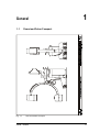
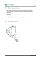
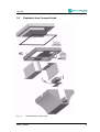
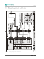
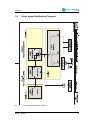
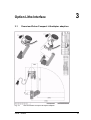
Ziehm Compact Litho
Service Manual
Supplement to Service Manuals
Ziehm 8000 & Ziehm Compact
28298 - 10/2005
Safety instructions
This manual does not constitute a complete catalog of all safety measures necessary for
the operation of the respective medical equipment, since special operating conditions may
require further measures. However, it does contain instructions which must be observed in
order to ensure the personal safety of operating staff and patients as well as to avoid
damage to property. These instructions are highlighted as follows:
WARNING
This is the highest level of risk. Personal injury or damage to property may occur if the
operator does not observe the instructions provided here.
CAUTION
This means that a situation exists which may require a decision or action on the part of the
user for optimum equipment performance or to avoid a minor hazard.
Note
Notes are informative. Additional useful information and hints are provided for the operator
here.
Intended use
The medical equipment is intended for fluoroscopies in the field of surgery, e.g. in
traumatology, orthopedics, neurology, urology, cardiology. Third-party devices and
components used in combination with the system must comply with the safety requirements
according to IEC 60601-1 and/or IEC 60601-1-1 or furnish proof of an equivalent degree of
safety.
Proper and safe operation of the system requires adequate transportation, storage,
assembly and installation as well as appropriate use and maintenance.
The limiting values indicated in this user manual must not be exceeded; this applies also
when putting the system into service.
Operation (U.S.A.)
In the U.S.A., Federal law restricts use of this device to trained personnel on the order of a
physician.
Authorized personnel
Only authorized personnel are allowed to assemble and/or repair the medical equipment
described in this manual. Authorized personnel are persons who have attended an
appropriate training course provided by the manufacturer.
Exclusion of liability
The manufacturer accepts responsibility for the safety, reliability and performance of the
system only if
•
any installation, modification or repair work is carried out exclusively by persons
authorized by the manufacturer;
•
the electrical installation of the room where the system is operated complies with the
requirements of VDE 0107 or the corresponding national regulations of the respective
country;
•
the system is used in accordance with the user manual.
The warranty becomes invalid in case that any repair, modification or installation work is
carried out by unauthorized personnel. No consequential damages will be accepted either.
The equipment conforms to Class IIb according to the Council Directive 93/42/EEC.
This user manual has been written and reviewed originally in German and translated.
Copyright
Copyright © 2005 Ziehm Imaging GmbH
All rights reserved.
Transmission or reproduction of this manual, exploitation and
disclosure of its contents to third persons is not permitted without
express written consent of the manufacturer. Infringements shall
entitle to damage claims.
Registered Trademarks
This manual may contain the names of registered trademarks or
brands, the use of which by third persons for their purposes may
infringe the rights of their respective owners.
Quality Standards
This manual was produced in compliance with the quality principles of
ISO 9001. The information provided in this manual may be updated at
regular intervals and is subject to change without prior notice.
Manufactured by:
Ziehm Imaging GmbH
Isarstraße 40
D-90451 Nuremberg (Germany)
e-mail: info@ziehm-eu.com
http://www.ziehm.com
In the U.S.A.:
Ziehm Imaging, Inc.
4181 Latham Street
Riverside, CA 92501
e-mail: info@ziehm.com
Rev. 10/2005
28298 - 10/2005
Table of Contents
Table of Contents
i
1
General
1.1 Overview Ziehm Compact ................................................................................
1.2 Ziehm Compact features ..................................................................................
1.3 View Compact head .........................................................................................
1.4 Exploded view Compact head..........................................................................
1.5 Wiring Compact head – mobile stand ..............................................................
1.6 Block diagram Compact ...................................................................................
1.7 Wiring diagram Compact..................................................................................
1.8 Video signal distribution Compact ....................................................................
1.9 Wiring module3 Compact .................................................................................
1-1
1-1
1-2
1-2
1-3
1-4
1-5
1-6
1-7
1-8
2
Monitor
2.1 18.1’’ flat-screen monitor ..................................................................................
2.1.1
Description ........................................................................................
2.1.2
Technical data...................................................................................
2.1.3
Power switch .....................................................................................
2.1.4
Connectors........................................................................................
2.1.5
On screen display .............................................................................
2.1.5.1 Locking and unlocking the on screen display ....................
2.1.5.2 Restoring the factory settings ............................................
2.1.5.3 Table of settings ................................................................
2-1
2-1
2-1
2-2
2-3
2-3
2-4
2-4
2-5
2-6
3
Option Litho Interface
3.1 Overview Ziehm Compact Lithotripter adaption ...............................................
3.2 Lithotripter adaption requirements....................................................................
3-1
3-1
3-2
28298 - 10/2005
-i
-ii
28298 - 10/2005
Contents General
1.1
1.2
1.3
1.4
1.5
1.6
1.7
1.8
1.9
Overview Ziehm Compact ................................................................................
Ziehm Compact features ..................................................................................
View Compact head .........................................................................................
Exploded view Compact head..........................................................................
Wiring Compact head – mobile stand ..............................................................
Block diagram Compact ...................................................................................
Wiring diagram Compact..................................................................................
Video signal distribution Compact ....................................................................
Wiring module3 Compact .................................................................................
28298 - 10/2005
1-1
1-2
1-2
1-3
1-4
1-5
1-6
1-7
1-8
-i
-ii
28298 - 10/2005
General
1.1
Fig. 1-1
1
Overview Ziehm Compact
Overview Ziehm Compact
28298 - 10/2005
1-1
1 General
1.2
Ziehm Compact features
• 18,1" single TFT flat-screen mounted on the horizontal slide of Mobile Stand
• Image memory for two images selected serial using the Mobile Stand keyboard.
(Module 3)
• Cross hair in the image selectable using the F-key on the Mobile Stand keyboard.
(Module 3)
• Stepwise digital rotation of the image 0 / 90° / 180° / 270° / 360° using the Mobile Stand
keyboard. (Module 3)
• Compact Mobile Stand can be linked with Monitor Cart.
1.3
Fig. 1-2
1-2
View Compact head
View Compact head
28298 - 10/2005
1 General
1.4
Fig. 1-3
Exploded view Compact head
Exploded view compact head
28298 - 10/2005
1-3
1 General
1.5
Fig. 1-4
1-4
Wiring Compact head – mobile stand
Wiring Compact Head - Mobile Stand
28298 - 10/2005
1 General
1.6
Fig. 1-5
Block diagram Compact
Block Diagram Compact
28298 - 10/2005
1-5
1 General
1.7
Fig. 1-6
1-6
Wiring diagram Compact
Wiring Diagram Compact
28298 - 10/2005
1 General
1.8
Fig. 1-7
Video signal distribution Compact
Video Signal Distribution Compact
28298 - 10/2005
1-7
1 General
1.9
Fig. 1-8
1-8
Wiring module3 Compact
Wiring Module3 Compact
28298 - 10/2005
Contents Monitor
2.1
18.1’’ flat-screen monitor ..................................................................................
2.1.1
Description ........................................................................................
2.1.2
Technical data...................................................................................
2.1.3
Power switch .....................................................................................
2.1.4
Connectors........................................................................................
2.1.5
On screen display .............................................................................
2.1.5.1 Locking and unlocking the on screen display ....................
2.1.5.2 Restoring the factory settings ............................................
2.1.5.3 Table of settings ................................................................
28298 - 10/2005
2-1
2-1
2-2
2-3
2-3
2-4
2-4
2-5
2-6
-i
-ii
28298 - 10/2005
Monitor
2.1
18.1’’ flat-screen monitor
2.1.1
Description
2
The 18.1’’ flat-screen monitor is a monocrome high resolution LC Display. It works as a seperate
module and is not integrated in the CAN bus. All settings and adjustments are made by a integrated setup menu.
Fig. 2-1
18.1’’ flat-screen monitor
28298 - 10/2005
2-1
2 Monitor
2.1.2
Technical data
Viewable Diagonal (inches)
18.1
Brightness (cd/m², typical)
600
Native Resolution (pixels)
1280 x 1024
Dot Pitch (mm)
0.28
Vertical Viewing Angle
170o
Horizontal Viewing Angle
170o
Contrast Ratio (typical)
600:1
VGA Input signal level at 75 Ohm
0,7Vp-p
BNC Input signal level
1Vp-p
Power (nominal)
70W
Monitor Weight
6.35 kg
Operating Temperature
0oC to 40oC
Storage Temperature
-20oC to 60oC
Relative Humidity (non condensing)
5% – 85%
2-2
28298 - 10/2005
2 Monitor
2.1.3
Power switch
There is a power switch on the rear side of the monitor.
Fig. 2-2
2.1.4
Monitor power switch
Connectors
+12V in
DVI / VGA in
Video in
RS232 interface
Fig. 2-3
Monitor connectors
28298 - 10/2005
2-3
2 Monitor
2.1.5
On screen display
2.1.5.1 Locking and unlocking the on screen display
The monitor is set up and adjusted by a on screen display. The functions are controlled by a integraded keypad.
Fig. 2-4
Monitor keypad
The on screen display is activated by pressing the "Menu" key. In the section "Setup" it is possible
to lock the menu.
Fig. 2-5
Menu "Setup"
If this function is activated, the menu will disappear. Instead of the menu you will get a message
"MENU LOCKED" for a short time. Now the access to the on screen display is denied. You will
get this message any time you press a key on the keypad.
Fig. 2-6
Menu locked
In order to unlock the menu, you have to press the keys " MENU" and "SCROLL" simultaneously
until you get a message "MENU UNLOCKED"
2-4
28298 - 10/2005
2 Monitor
Fig. 2-7
Menu unlocked
You can use the key combination "MENU" and "SCROLL" also to lock the on screen display
directly. This function will toggle between "MENU LOCKED" and "MENU UNLOCKED"
2.1.5.2 Restoring the factory settings
In the section "Defaults" of the on screen display you can restore the factory settings. The factory
settings are not optimized for the video output of the image memory.(Bios Version 58B0109 C 01)
The top line refers to the input connector and the timing. BNC 733 x 568 / 50 Hz for Compact Flat.
M
Fig. 2-8
Menu "Defaults"
If the factory default was performed, the image will be outshining and not centered.
Refer to the table of settings for correct values.
28298 - 10/2005
2-5
2 Monitor
2.1.5.3 Table of settings
Picture
Horizontal Position
285
Vertical Position
47
Sharpness
oooXOO
Phase
25
Frequency
908
Scaling
Aspect
Gamma
Gamma
2,2
Setup
Menu Position
top left
Menu Orientation
Portrait
Menu Language
English
DPMS (power management)
off
Auto Source Select
on
Brightness / Contrast
Contrast
99
Brightness
50
Backlight brightness
100
2-6
28298 - 10/2005
Contents Option Litho Interface
3.1
3.2
Overview Ziehm Compact Lithotripter adaption ...............................................
Lithotripter adaption requirements....................................................................
28298 - 10/2005
3-1
3-2
-i
-ii
28298 - 10/2005
Option Litho Interface
3.1
Fig. 3-1
3
Overview Ziehm Compact Lithotripter adaption
Overview Ziehm Compact Lithotripter adaption
28298 - 10/2005
3-1
3 Option Litho Interface
3.2
Lithotripter adaption requirements
• Mechanical interface for a Lithotripter source: The focal spot of the lithotripter source must
be in the intersection of the central beam and the angulation axis of the C-arm.
• Reinforced bearing blocks for the orbital rotation of the C-arm.
• Horizontal slide blocked at position "0 cm" indicated on attached scale.
• Vertical lift restricted to 230 mm.
• Wig-Wag (10-0-10 degrees) blocked at 0 position.
3-2
28298 - 10/2005