1
Film-Tech
The information contained in this Adobe Acrobat pdf
file is provided at your own risk and good judgment.
These manuals are designed to facilitate the
exchange of information related to cinema
projection and film handling, with no warranties nor
obligations from the authors, for qualified field
service engineers.
If you are not a qualified technician, please make no
adjustments to anything you may read about in these
Adobe manual downloads.
www.film-tech.com
The Victor Guarantee
Each new British-madeVictor 16 mm. Sound-onFilm Animatophonemanufacturedand/or suppliedby
us is guaranteedto be free 'from defectsdue to faulty
material and workmanshipfor the period of TWELVE
MONTHS'from the time' of delivery to the Retail
Purchaser.
Our obligation under this Guaranteeis limited to
repairrng or replacing at our factory any part of the
machine-excludingvalves,projector, exciterand pilot
lamps and photo-electriccells-which shall within such
period of TWELVE MONTHS be returned to our
Distributor for transmissionto our Head Office or
Factory free of cost to us, and which on examination
be found to have been so defective at the time of
delivery to the Retail Purchaserand that such part
has not been interfered with in any way or damaged
through maltreatment.
This undertakingis in lieu of all other guarantees
or warranties expressedor implied and of all other
obligationsor liabilities on our part directly or otherwise available to the origrnal purchaser or any other
person. No agentis authorisedto assumefor us and
we do not acceptany liability exceptas abovesetforth.
i.;;.i rr
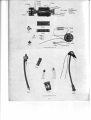
ILLUSTRATIONS
Ill. No.
Page
0 . Projector open for use
4
1
Speaker
l.
2 . Transformer
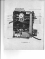
9 . ProjectorUnit with part numbers
i 0 . Gearing and Flywheel Assembly with part
A
16
numbers
Ill. No.
Page
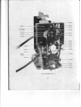
11. Shutter and Intermittent Mechanism,etc., with
part numbers
18
12. Lamphouse and Light CondenserU:its with
part numbers
..
19
I J.
Motor Secti,ons
with part'numbers
..
..
20
1 4 . Photo-ElectricCell, Exciter Lamp and S o u n d
C h a n n eU
l n i t sw i t h p a r t n u m b e r s
. 2 0
DIAGRAMS
Ill.
3.
4.
5.
6.
No.
ThreadingFilm, first stage
Threading Film, secondstage
Threading Film, third stage
OperatingControls
..
..
..
..
Page
5
5
5
6
ltl. No.
7. Oiling Points
Timing the Projector
8. Amplifier Wiring Diagram
Motor Wiring Diagram
.
.
.
..
Page
6
ll
1
2
t-)
INDEX
Page
Amplifier Circuit References . .
Amplifier, Removing from Case
Amplifier Voltage Check
Belts
Blowing of Fuses
Cam OscillatingGear .
Circuit Reference,Amplifier
Clutch and Trip
Controls,Sound..
Dimensions of Equipment
Drive Belt
Exciter Lamp
Film Capacity
12
10
l3
7,l0
o
10
12
8
8
a
Film Over-running Feed Spool
F i l m P e r l o r a t i o n sC h i p
Film Tear at Sprocket
Film Scratches
Flicker
FlyrlheelUnits .
F o c u s s i n gP i c t u r e
Focus, Picture partly out of
Fuses
Fuses,Blowing of
Gate
General Description
cenerai rr;p""ti;;
Ceneral Orerhaul
Chost
..
:.
Covernor
Hand Operating Knob
lllumination
Inspecting the Projector
Inspecting the Sound System .
Insufficient Light on Screen
Intermiftent lVlechanism
Lamps Blowing . .
I arrip, Exciter
Lampnouse
Lamphouse, Removing
I amp, Projector. .
LCNS
Light, Insufficient on Screen
Loop, Loss of Lower
Loop, Loss ofTop
Microphone, to Use
Motor
Motor Boating . .
Motor not Running
Motor, Removing
Noise
Oiling
Operating Instructions ..
Photo-Cell
Pholo-CellVoltage
,
l0
8
4
9
9
9
9
9
lt
6
9
8
9
7
4
7
l0
7,11
5
8
7
8
9
10
o
8
7
l0
7
7
9
o
o
'7
7
o
o
l0
8
7
6
8
6
Page
Picture Unsteady
Power Requirements
Pro:eooi,-Insp.iiio"oi
..
.:
Projector, Removing from Case
Projector Troubles and their Remedies
Quality of Sound
RecordPlayer,ToUse
..
..
Removing Amplifier from Case
RemovingLamphouse. .
..
.:
Removing Motor
Removing Projector from Case
Removing Side Plate
Rewinding
Reversing
Rollers
..
Running of Film
SafetyShutter
Scratches
Scratches,
Film ..
ServiceParts,Spares
Setting-Up Equipment
Setting-Up for lnspection
Setting-Up for Operation
Shuttle
Side Plate, Removing
Sound Controls . .
SoundDrum and Slit
Sound,Quality
Sound System,Inspectionof . .
Spare ServiceParts
Speaker
Speeds
SpeedVariation
Sprockets
SprocketGuard
Starting Levers
Still Pictures
Stop Projector
Synihroriisation
..
::
Takc-Ups
Take-UpPulleys
Test Film
ThreadingFilms (Siient)
T h r e a d i n gF i l m s( S o u n d t
Timing
Tilting Projector
Travel Ghost
Trip and Clutch
Unsteady Picture
Valves
Voltage Check, Amplifier
Voltage, Photc-Cell
..
w"ieiiibirq"ip'r'"nt
9
4
7
l0
9
8
7
10
l0
10
l0
l0
b
t)
..
.:
..
7
b
ll
8,9
9
1 4 ,1 5
5
7
6
1, 10
10
8
8
8
8
14,15
8
7
9
7
l1
l0
6
o
5
8
l1
8
5
lt
o
t0
8
9
8
I J
..
::
..
..
o
4
GENERAL DESCRIPTION
Film Capacity:
From 100 to 1,600ft. of erther silent or sound
16 mm. film. With additional extensionarms up
to 2,000ft.
Power Requirements:
110 volts, 50 to 60 cycles,A.C. Watts 950.
Dimensions:
ProjectorOutsidecase-I4] x 9| x 13] in.
SpeakerOutsidecase-l8$ x l0* x 16$in.
Step-downTransformerl0x7x5in.
Weight:
50 lb.
Projector45 lb.
Speaker-Transformer-27 lb.
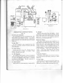
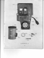
SETTING-UP EQUIPMENT
Illustration l.
1. Remove back from speakercaseby loosening
two oatches at top. Swing back open and slide to
one side.
2. Remove cover of speaker at front of speaker
case.
3. Insert one end of speakercable in one of the
sockets on speaker-it does not matter which one
as sockets are wired in parallel. The other socket
is used when a second speaker is required.
4. Seethat matching panel on speaker is plugged
into Figure I when one speaker is used and Figure
2 when two speakers are used, etc.
5. Set speaker at front of room, fairly high,
facing slightly downward towards the centre of the
audience.
6. Connect other end of speaker cord in socket
No.2 (Illus. 6).
7. Connect step-down transformer lead into
socket No. 2 (Illus.6) having first checked that the
transformer input voltage tappings correspond with
mains voltase.
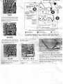
Illustration 2.
Threading Film:
1. Remove reel arms from bottom of case. Place
in sockets so that shafts are at the front.
2. Place take-up belts in small pulleys on both
reel arms for small reels and in large pulleys for
1,600ft. reels. Nearest, or inside belt goes to rear
arm. Back or outside belt goesto front arm. Both
belts must be crossed (see lllus. 5), so that both
reels revolve clockwise when machine is running in
forward motion. Feed reel goesto rear and take-up
reel at front.
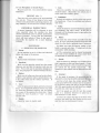
3. (Refer to lllus.4). Open upper and lower film
shoes (M) and (G) by pulling out on pivot ends
shown by arrow. Open tension rollers against (A)
and (C) by pressing down. (Illus. 3). (1) Thread
film straight acrossfrorn full reel to hub oftake-up
reel. (2) Pull generousloop of film down to bottom
of case. (Illus. 4\. Thread film under sound
sprocket (A), over sound drum (B), and under
impedance roller (C). Next open lens mount (D)
and thread film up in front of roller (E), between
red rollers (F), to under side of drive sprocket and
close film shoe (G), over in front of front film
roller (H) and back of roller (I). Now go back to
impedance roller (C) and thread back from
impedance roller, under and behind roller (J), into
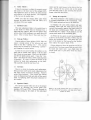
film channel (K), and close lens mount. (Illus. 5).
Thread film behind and over roller (L), over top of
drive sprocket, close upper film shoe (M) and
continue behind the roller (N) as shown. Check
both upper and lower film shoesto ascertain that
they are locked in closed position and that perforations of film fit over sprocket teeth. Threading:now
appears as shown in llhrs. 5.
Illustration 3.
A
Ittt
--.foi,yo
/upeosct
nur
Illustration 4.
Synchronisation :
For perfect synchronisation of sound and
picture, there must be exactly 25 "frames" or
pictures between aperture (K) and sound gate (B),
loop as shown in lllus. 4.
Hand Operating Knob:
Revolve a few turns to check movement of film
and to make sure film is in channel (K) and that
loops remain as shown in lllus. 5.
Silent Film Threading:
Same as for sound fllm except omitting sound
head (A, B, C, E) with lower film loop from in
front of roller (J) to behind roller (F).
I
Illustration 5.
lpmcrcr
0nta
Iflltto
ttlf
; toatil rt tIrrqlt
I ttttt rot6f-
Cotftot PANEI
| 0t nEAn ttO
.
of catE
i 2itfltt
isl!t!!_
l7
Stqtttt
Oil 7 places marked by red dots.
Illustratnn l.
Illustration
6.
OPERATING INSTRUCTIONS
(Illus. 6)
To Set Up for Operation:
Seecontrol panel on rear of projector case. Set
tone control (3) at midway position. Set volume
control knob (4) at midway position. Push down
exciterswitch(5). For soundfilm pushdown speed
switch (6).
To Rewind:
Remove take-up belt from reel pulley. Attach
rewind belt to rear pulley (belt not crossed), thread
end of film back from take-up reel to rear and
empty reel. Set motor to slow speed on switch (6.)
Pressdown on rewind switch (15).
Photo-Cell Voltage :
Loosen lens lock screw (9). Revolve lens in
mount until focus is sharp. To frame: Turn
knurled framing screw (19),
(Seeupper round opening (16) on right front of
case) adjust with small screw-driYer. Check setting
before each show with exciter lamp on and with
volume turned on full (without film) turn voltage
control clockwise until excessive humming or
squealing begins. Turn knob slowly back until hum
is less noticeable. Then turn volume back to
'olow."
Too much photo-electric cell voltage
results in objectionable noise ; too little, in loss of
volume.
To Tilt Projector :
To Reverse Frojector :
Use knurled knob located on top of projector
case near the front centre. Revolve anti-clockwise
to raise the projector until image is properly
positioned on the screen. Revolve clockwise to
lower to original positiOir.
Push down roller shaft (11) as far as it will go.
To resume forward movement, push up on roller
shaft (11).
To Run FiIm:
To start projector-raise operating lever (8).
Push down projection switch (7) (motor and lamp
now operating).
To Focus Ficture :
To Stop Projector:
Push forward on roller shaft (10). Switch-off (7).
To Show Stills:
Stop projector by pushing forward on shaft (10).
Raise still lever. Bring desired picture into
position by revolving hand operating knob (14).
_{
i
To Use Microphoneor RecordPlayer:
Plug into jack (12). Use control (20)for volume
adjustment.
OILING Qttus.7)
Thereare only sevenplacesto oil, eachindicated
by a red dot. Three or four drops of oil at each
ofthese sevenplacesbeforeoperatingprojector,are
fully sufficient.Do not usemore oil than directed.
7.
Lens :
Clean lens carefully. Use lens cleaning tissue or
chamois leather. (Remember that optical glass is
much softer than ordinary glass).
8. Lamphouse:
Releasethe lamphouselocking screwand remove
the lamphouse. Clean the condenser and reflector
with tissue.
9. Lamp:
GENERAL INSPECTION
A general inspection will be adequate in most
cases, especially where the machine has been
checked periodically and its general performance
known in advance. In any case the preliminary
check will soon indicate if there is any need to
disassemble the machine for a more elaborate
overhaul.
PROCEDURE
A.-INSPECTING
THE PROJECTOR
1. Set-up :
Set the machine up as for a show and check all
cables and plugs in the process.
Check the lamp for excessiveblackening adjacent
the condenser, and wipe it clean. If the glass is
blistered or if the filaments seem to sag, replace the
lamp immediately.
10. Motor:
(a) Check the motor brush accessible from the
front. If worn, remove the projector from caseand
check the other brush, replacing them if necessary.
(b) Make sure that the bearing surface of the
brush is smooth and shiny. If rough and oily the
commutator needs cleaning.
(c) The commutator can be cleaned moderately
well if not in bad condition by using a small piece
of cheeseclothor extra fine abrasive.
2. Belts:
Replace belts if stretched or kinked.
3. Sprockets:
Make sure the sprocket guards have the proper
clearance and see that the sprocket teeth are not
worn. Worn teeth can be extremely damaging on
film. Seeparagraph l4-General Overhaul Section.
4. Rollers:
Make sure all rollers are clean and revolve freely.
If there is any question make a special check to see
if the rollers have any flat surfaces anywhere. If
so, replace.
5. Gate:
Clean the gate, pressureplate, aperture and sound
drum. An orangewood manicure stick is very good
for removing encrusted emulsion and for getting
the corners of the aperture free ftom fuz:2. Check
"rails"
on which
carefully for wear of guides or
the film rides.
6.
Shuttle:
Check for wear on shuttle teeth.
11. Speerls:
Turn the motor on, listening to its sound and see
that it operates at silent and sound speeds. (Count
80 and 120revolutions ofthe l2-tooth feed sprocket
per minute for the speeds respectively). The
operation of the switches can be determined at this
time.
12. Governor:
If the speed is incorrect, the governor can be
adjusted by removing the grille underneath the case.
(a) First of all, clean the contact points. The
sound speed(24 F.P.S.) contacts can be recognised
by the heavier spring and also by the fact that the
16 F.P.S. speedcontactsare held down by a straight
lug while the other lugs are curved.
(b) If the speeds are still off, turn the contact
screw in a clockwise direction to speed up or
anti-clockwise to slow down.
(c) Clean the copper slip rings at the ba.ck of the
governor and make sure the brushes are not worn
and that thev are making good contact.
13. Clutch anil Trip:
Check the operation of theseunits.
14. Take-ups:
The operation of these is trcst checked with film
threBded on the machine. Inadequate pull or
jerkiness may mean new belts or adjustment of the
clutch pulleys.
15. Illumination :
Turn on the lamp and make sure the light on the
screenis even all the way across. (A photo-cell type
exposure meter will be found useful for this
although visual inspection will usually be satisfactory). If necessaryadjust the lamp sideways in the
lamphouse by slackening knurled nut (17) Illus. 6.
tock tight when in desired position.
16. Scratches:
Make a continuous loop of about 24 in. of new
(unused) film which is very soft and run through the
mechanism a dozen times or so. This will quickly
indicate if there is any scratching at the gate. If
any abrasion marks show up, the front and back
gate plates and other parts such as sprocket guards
must be cleaned and checked verv carefully.
20. Sound Drum and Slit:
Clean these very carefully. An ordinary pipecleaner is as effective as anything. Lens tissue or
even cheesecloth,with or without an orangewood
stick is satisfactory. Make sure the guides are not
worn.
21. Valves:
While the operating of the valves can be gauged
by listening to a test reel, it is urged that they be
removed and checked in a standard valve tester. A
good tester will show when a tube is near the end
of its useful life and will avoid subsequent trouble
if the machine is used a lot just after an incomplete
check.
22. Fuse:
Some users seem to think this is not important
and have replaced the regular fuse with other fuses
up to 10 amp. capacity. The fuse is for protection
and 2 amp, is the maximum size to be used, except
with machines bearing serial number Prefix B,
where a .25 amp. fuse is to be used.
23. Test Film:
17. Noise:
IJse a sound object, with which you are thoroughly familiar. Then you can quickly recognise any
variation from standard and investigate further.
If the machine is noisy, an overhaul is indicated.
(See General Overhaul).
24. Sound Quality:
B.-INSPECTING THE SOUND SYSTEM
18. Exciter Lamp:
Remove and check for excessiveblackening and
for saggingfilament. Wipe clean and replace. Make
sure the lamp is aligned with the slit. This can be
seeneasily when photo-electric cell is removed and
a piece of paper held in its place.
(a) Wows. Slow-speedvariations usually caused
by improper operation of the impedance roller
assembly. Make sure the flywheel is working
smoothly and that the pressureroller is free.
(b) Flutter.
Relatively high-speed variations
improper
functioning of the sound
usually due to
sprocket filter mechanism. Check the clearanceand
smoothnessof the sprocket and its roller.
25. Sound Controls:
19. Photo-Cell:
Remove cap, wipe clean. (Correct functioning of
the photo-cellcan be determined by noting the hiss
when the amplifier is turned on and without film,
and with the photo-cell voltage adjusting screw set
properly. Sometimesphoto-cell breakdown will be
checkedbest by listening to a test film with another
photo-cell in the machine).
Check the operation of switches, volume and
Listening to the sound while
tone controls.
operating the latter will indicate whether the
amplifier needsfurther attention.
26. Speaker:
Wipe off dust from speakercone and make sure
it is not cracked or broken.
SOMECOMMON PROJECTOR
TROUBLESAND THEIR
REMEDIES
1. Lamps Blow Out Prematurely:
(n) High-line Voltage : This is nearly always the
causeof the trouble. Check line with a good meter.
The power companies often boost the supply
voltage to compensatefor heavy loads in outlying
districts. Voltages also tend to vary with the
general industrial load and may vary greatly in
different parts of the same town at the same time.
(b) Incorrect Lamp llsed : The larnps usually
stockedby the dealerare rated for I l0 volts and are
suitablefor line voltagesoffrom 100 volts to 115
volts.
2.
Main Fuses Blow:
This indicatesa short or earth in the wiring. Test
the projector and amplifier separatel-v-.
Localise the
fault by disconnectingmotor, lamp, governor, etc.,
as necessaryuntil the faulty part is found.
3.
Motor Will Not Run:
(a)
(6)
(c)
(d)
4.
Check cablesand plugs.
Check motor brushes.
Check main switch contacts.
Check mains fuse.
Speed Variation :
Clean governor contact points and readjust
setting if necessary. See General Inspection,
paragraphs 12 (a) and (b).
5. Loss of Top Loop:
(a) Main sprocket guard may not be seating
properly.
(b) Film perforations may be torn.
6. Loss of Lower Loop:
(a) Torn perforations.
(b) Film not threaded properly at gate.
(c) Check sprocket guards and gate clearance.
(d) Excessivewear of shuttle and cam.
7.
Film Scratches :
This is usually due to an accumulation of
hardened film dust on aperture plates (or sprocket
guards). It may also be due to physical damage to
extremely smooth surface of gate plates or wear of
guides on back film channel, aperture plare, or
sound drum. If so, replacementis indicated.
8.
Pictures Unsteady :
(a) Film badly shrunken and perforation chipped.
(6) Wear on shuttle and cam or other parts of
intermittent mechanism.
(c) Wear on aperture and pressureplates.
9. Flicker :
(a) Speed on governor set too slow.
(b) Cam gear replaced "out of time."
General Overhaul, paragraph 15.
See
10. Film Over-runs Feed Spool:
Insufficient friction on feed spindle. SeeGeneral
Overhaul, paragraph 12.
11. "Motor-Boating" :
Sound drum not replaced all the way in, causing
film misalignment.
12. Film Tears at Sprocket:
If sprocket is replaced without hardened thrust
washer between it and the casting, the sprocket
teeth will not align with groove of idler rollers.
13. Film Perforations Chip:
(a) Worn sprocket teeth.
(b) Worn shuttle or shuttle teeth.
(c) Tension at gate insufficient.
(d) Badly shrunken film.
14. Insufficient Light on Screen:
(a) Still picture shutter "up."
(D) Dirty lens, condenser,or reflector.
(c) Lamp old, blackened or dirty.
(d) Low-line voltage.
(e) Dirty screen.
(/) Position of lamp.
See General Inspection,
paragraph 15.
15. Picture Partly Out of Focus:
(a) Gate alignment tampered with-must
parallel. Illus.9. ScrewNo. 18177.
(D) Dirt on lens.
be
(c) Projector not square with screen.
I
i
I
'fravel
16.
Ghost:
A picture with a "streaky" effecton the screen
usually indicates the cam or shutter has been
replaced"out of time." SeeGeneralOverhaul,
paragraph15.
GENERAL OVERHAUL
The General Overhaul involves dismantling the
projector in four or five main operations as below :
1. Remove Projector from Case :
The projector is held in the case by four screws
at the bottom of the case. After removing the
screws, tilt the projector forward carefully to gain
accessto the plugs connecting the projector to the
amplifier. Disconnect these plugs.
2.
given refer to the spare parts list and assembly
photographs.
6. Large Cam Oscillating Gear:
(a) If improperly engaged with small cam gear,
the machine will be noisy. To adjust, loosen the
two screws on part 17967 and the two screws
adjacent screw 18030(Illus. ll). Screw 18030is an
eccentric. Turning it moves the two cam gears
apart or closer. The proper position will be the
quietest but care must be taken not to set the gears
too close together. After adjusting, be sure to
tighten the above locking screws.
(6) The gear itself rarely needs attention but must
be removed to get at the shuttle tension spring,
18068. To do this, loosen the two screws on the
casting lug adjacent the spiral gear shown in
Illus.10.
Remove Amplifier:
The amplifier is held in the case by two screws
at the side (near the controls) and four screws at
the rear.
3.
1.
Remove Lamphouse:
(a) Check for wear or loosenessof the sides of
the shuttle against the heart-shapedcam. Replace
if there is play between cam surfaces and shuttle.
Care must be taken when replacing shuttle that the
claws withdraw clear of the film channel and also
give sufficient engagement to the film.
This
adjustment is carried out by loosening the two
screwsreferred to in paragraph 6 (b) and positioning
the oscillating gear assemblyuntil the correct claw
engagement and withdrawal is retained.
Loosen the thumbscrew holding the lamphouse
and remove that. Then remove the five screws
holding the remaining part of the lamphouse unit
to the main casting of the projector. This exposes
the shutter and intermittent mechanism, etc.
(Illus. ll).
4.
Remove Siile Plate:
This plate is held by four screws and covers
the take-ups, clutch pulleys, flywheels, etc. (Illus.
10).
(b) Make sure the shuttle teeth are not badly
worn or rough. Minor rough spots on shuttle teeth
can be stoned smooth provided care is used.
(Caution is urged if this is tried).
5. Remove the Motor:
This is necessary only when the commutator or
bearingsneedattention. To remove the motor from
its housing, proceed as follows :
(a) Remove two screwsfrom front and also back
of housing.
(b) Remove brushes.
In the event of any question of the best functioning of this vital part, replace the entire shuttle
rather than take any chances of subsequent
complaints.
(c) Remove wires and terminal plate.
THE
MAIN
INTERMITTENT
Shuttle :
This part 37416is the heart of the entire mechanism and must be checked carefully.
8.
Main Drive Belt:
Remove belt retaining guard 18218 (Illus. ll),
and replace belt if necessary. (Be sure to replace
o'step" to the right.)
this with the short
MECHANISM
Under the following headings are given the steps
most often necessary for properly checking the
projector mechanism.
Owing to the extreme
accessibility of the mechanism, replacements even
of vital parts are easy and positive. The numbers
Starting Lever Unit :
If the roller 37381 is loose on the shaft replace
the entire assembly,
9.
l0
10. Safety Shutter:
rollers and by small screwsin the slots at tlle free
ends. Loosen the two screwsand set the guides
until the back roller is just touching the sprocket
flange-then lock the screws.
It may be necessaryto adjust the eccentricscrew
(the screw at the lower end of the spring) 18015.
This adjustment raises or lowers the safety shutter
with relation to the main aperture. The alignment
of the two can be readily seen.
15. Timing the Projector:
Make sure that the shutter slides quite freely
between the guide screws 17979 and 17981, so it
will drop of its own weight.
I l.
The Victor projector is the simplest to time and
it is almost impossible to do it incorrectly. Only
TWO simple precautions have to be observed.
(a) Replace the cam pulley shutter and gear
assembly 37391 with the small end of the cam
centred (horizontally) against the punch mark on
the large cam oscillating gear 37406. (It will be
noticed that one "spoke" of the pulley is over tbe
centre punch mark of the oscillating gear.
Flywheel Units :
The only adjustment likely to be needed here is
so the shafts on which they are fastened have a
slight end play, approx. .004. Do nol tighten them
up too close to the bushing or too much drag will
occur. This is worse than if thev rvere too free.
(b) While the two gears are still set horizontally
as above, set the shutter assembly37360so that the
blades are horizontal also. This places the open
part of the shutter at the top and at the bottom,
then replace the support plate 37356.
12. Take-up Pulleys:
IJneven action of these pulleys (18123,Illus. l0)
causes a jumpy action of the take-up and may
result in the film " spilling over. " This uneven
action may be caused by oil becoming "gummy"
and clogging the ratchet action.
If these things are done the projector will be set
correctlybut it is alwaysa good idea to turn it over
by hand and make sure ; just check that the
shuttle teeth start to pull down while the shutter
is closed.
Loosen the set screw holding the pulleys on the
shaft and be careful when sliding it off the shaft
that it does not come apart. Place on a flat surface
and lift the pulley pieces apart. Clean the "runways" and check the rollers, 18070,replacing them
if necessary. It is easy to check the action of the
ratchets by hand after replacement on the shaft.
This assemblyshould be run free of oil.
13. Governor:
Once in a while the brushes need replacement.
(The governor itself rarely needs replacement, but
slip rings require occasional cleaning). Remove
motor from projector. Then loosen the locking
screw on the governor hub and slide off the motor
shaft. In replacing, allow the proper clearancefor
the brushes.
14. Sprocket Guard:
The sprocket guard rollers are set to the proper
clearance by adjusting the curved guide lock
members 37418 and 37479. These are fastened on
the main casting by the shafts of the right-hand
Shutter to be in this position when spot on oscillating gear
is in line with rib of cam pulleys-with
high side of cam in
position as shown.
11
AMPLIFIER WIRING DIAGRAM
Illustration 8.
Circuit Ref.
Description
Circuit Ref.
R1
R2, R17, R25
I
Potentiometer.250.000ohms.
Resistor, 1 megohm,+ waft, 20'%
tolerance.
R3
Resistor,4,700,000ohms, * watt,
20)( tolerance.
R4, R9
Resistor,2,200,000ohms, t watt,
2O)( tolerance.
R5
Potentiometer,50,000ohms.
R6
Resistor, 2,200 ohms, * watt,
209( tolerance.
R8,R14
Resistor, 100,000ohms, ] watt,
20)( tolerance.
R7, R20, R22, R28 Resistor,470,000ohms, * watt,
20/o tolerance.
R10
Potentiometer,1,000,000ohms.
R l 1 , R 2 6 ,R 2 7
Resistor, 10,000 ohms, + watt,
20)( tolerance.
R13
Resistor, 4,700 ohms, l- watt,
20)( tolerance.
R l 5 , R 1 6. .
Resistor, 22,000 ohms, I watt,
1O)( tolerance.
Rl8
Resistor, 1,000 ohms, * watt,
2Ol tolerance.
R19
Resistor, 22,000 ohms, I watt,
20)( tolerance.
R21
Resistor, 200 ohms, 10 watt,
709{ tolerancn.
R24
Resistor, 100,000ohms, ] watt,
2O)( tolerance.
Rl2
Potentiometer, 5,000 ohms.
cl, c8,
Condenser, Paper 0.1 UF 500 v.
c9.
WKG 20% tolerance.
c2, cl3
Condenser,
0.01UF 500v. WKG
25/" toleratce.
C 1 2 ,C 7
C4
C5
C6
c10
ct4
Vl, V2, V3
V4, V5
V6
LI
F
S2
S1
TI
T2
PI
P2
P3
P4
P5, P6
R29
t2
Description
Condenser,Paper0.1 UF 250 v.
WKG 25% tolerance.
Condenser, Electrolytic 10 UF
25 v. WKG-20%+50%.
Condenser,Paper0.05 UF 500 v.
WKG 2O%,tolerance.
Condenser, Electrolytic 2 UF
500 v. WKG-20%+50%.
Condenser,Electrolytic, 16+ 16+
8 UF 450v. WKG-20%+507.
Condenser, Electrolytic, 25 UF
50 v. WKG-20%+50%.
Valves, OsramZ 66.
Valves, Osram KT 66.
Valve. Osram U 52.
Choke 2H at 160 MA.
Fuse .25 amp or 2 amp.
Switch.
Switch, SinglePole, SingleThrow
Transformer, 6,600 ohms to 600
ohms.
Transformer,Input 110 v. 4016O
Cycles; Output 385-0-385
at 160
MA, 5 v. 3 amps,6.3v.3.3 amps,
Centre tap, 5v. 6.5 amps.
Plug and Socket.
TelephoneJack.
Two-PinPlug and Socket.
4-PinSocket.
Mains Connector (Apparatus
Member).
Resistor, 22,000 ohms, ] watt,
20/o tolerance.
AMPLIF'IER VOLTAGE CHECK
For Models without SerialNumber prefix
Letter
For Models with SerialNumbersprefixed
AandB
Meter Used-l ,000 ohms per volt
Yolume Control-Maximum
Component
Meter Range
Reading
lgeter Used-l ,000 ohms per volt
Volume Control-Maximum
Component
Meter Range
Reading
Output ValvesV4 and V5
A Screen(Pin 4)
500v.
B Anode (Pin 3)
500v.
465v.
460v.
Output ValvesV4 and V5
A Screen(Pin 4)
500v.
B Anode (Pin 3)
500v.
3 1 0v .
300v.
Phase Inverter V3
A Anode (Pins 3, 4, 5)
500 v.
22Ov.
Phase Inverter V3
A Anode (Pins 3, 4, 5)
500 v.
160v.
Driver V2
A Anode (Pins3, 4, 5)
500v.
190v.
Driver V2
A Anode (Pins3, 4, 5)
500v.
120v.
Pre-Amplifier Valve Vl
A Screen (Pin 4)
B Anode (Pin 3)
250v.
250v.
l0-15v.
lO-12 v.
Pre-Amplifier Valve Vl
A Screen (Pin 4)
B Anode (Pin 3)
250v.
250 v.
9-10 v.
9-10 v.
Grid Bias Reading
V.1 Pre-Amplifier
(Pin8)
V.2 Driver
lPin 8)
V.3 Inverter
(nin A)
V.4, V.5 Output @n Sj
5 v.
5 v.
100v.
100v.
.3-.4 v.
2.5-2.7 v.
60-65 v.
38-40 v.
Grid BiasReading
Vl Pre-Amplifier(Pin 8)
V2 Driver
(Pin 8)
V3 Inverter
(Pin 8)
V4, V5 Output
(Pin)
5 v.
5 v.
100v.
100v.
.2-.25 v.
1.7-1v.
38-40 v.
20-24 v.
MOTOR WIRING DIAGRAM-TWO-SPEED GOVERNOR
TWO SPEEO SWITCH-
l3
SPARE,SERVICE PARTS
Description
Ref. No.
{F17856 2.BA. Cap Nut
11864 Motor Switch
iF17865 Lamphouse Terminal Plunger
17867 Lamp Socket
17869 Lamp Adjusting Stud Assembly
17876 Still Picture Shutter Lever Pivot
17877 Lamphouse Terminal Plunger Spring
17878 Lamphouse Terminal Plunger Insulating Washer
iel7880 Rewind Belt Guard
17881 Lamp Adjusting Nut
17885 Loop Tension Roll Arm Assembly
17886 Tension Roll Grip
17887 Loop Tension Roll Arm Sub-Assembly
*17892 Loop Tension Roll Assembly
*17894 Sound Sprocket Tension Roll Arm Assembly
17895 ReverseSprocket Tension Idler Roll
17897 Sound Sprocket Tension Roll Arm Sub-Assembly
Ref. No.
Description
'&18063 Shuttle Rod Bearing Assembly
,F18064 Shuttle Oiler
18068 Shuttle Spring
18070 Reel Shaft Clutch Roller
*18081 Reel Arm Holding Screw
{i18084 Automatic Trip Plunger
*18090 Automatic Trip Roll (Inside)
*18091 Automatic Trip Roll (Outside)
18092 Hand Trip Knob
'F18097 Trip Lever Tension Spring
'F18098 TensionRoll Spring
{t17901 Sound Sprocket Tension Roll Assembly
17907 Tension Roll Spring Hook
*17909 Lamp Switch
x179ll ReverseSwitch
17923 Cap Nut 4.BA. (Hexagon)
*17940 Sound Sprocket Flywheel Hub Assembly
17942 Filter Springs (Sound)
*17948 Sound Sprocket Assembly
'*17949
Sound Sprocket Gear Shaft
*17950 Sound Sprocket Drive Gear
17951. Sound and Silent Switch Insulator
17953 Sound Channel Cap and Nameplate Assembly
*17965 Body Terminal
*17967 Shutter Housing Dowel Plate Assembly
*77971 Jack Shaft Collar
x17973 Shutter Drive Gear
*17974 Intermediate and Drive Gear Assembly
17975 Jack Shaft Support Washer Assembly
17976 Jack Shaft Oil Tube
*17979 Safety Shutter Guide (Upper)
tF17980 Shutter Housing Terminal Plate Insulator
xl798l Safety Shutter Guide (Lower)
x17983 Safety Shutter Trip Spring
*17992 Feed Sprocket Drive Pinion Assembly
17997 Cam Shaft Pin
18008
l80ll
18013
18014
,Fl80l5
18016
,&18017
18019
18022
't18030
18036
18037
ik18038
18040
*18041
18051
18053
18056
18057
Starting Lever Knob (Lower)
StartingLeverPlateSpringHook
Starting Lever Pivot
Starting Lever Pivot Washer
StartingLever Spring
Starting Lever Knob (Upper)
Hand Operating Knob
Hand Shaft Retaining Screw
Cam and Gear Assembly
Cam and Oscillating Gear Centre Adjusting Pin
Spiral Gear Shaft and Hub Assembly
Spiral Inter-Pinion Assembly
+ in. BSF. Cap Nut
Spiral Gear Thrust Ball
Inter-Spiral Pinion Thrust Washer
Oscillating Gear Shaft Sleeveand Bush Assembly
Oscillating Gear Thrust Washer
Spiral Drive Pinion Key
ReverseTake-up Clutch Cam Assembly
I A
18108
18112
18116
18117
,t18118
*18122
i*l8l23
18124
*18125
18126
18134
18139
18140
i(18146
tFl8148
18150
't18168
18171
it18175
18176
*18177
*18178
18179
18181
18182
18183
18184
18185
*18191
Tilt Knob
Tilt Feet
Film Trap Roll
Film Trap Roll Shaft
Take-up Operating Lever Assembly
Take-up Snubber Spring
ReverseTake-up Clutch Pulley Assembly
ReverseTake-up Clutch Pulley Bearing
Take-upFeed Roll
Take-up Belt
Small ShoeGrooved Roll
Small ShoeRoll (Outer)
Small ShoeRoll (Inner)
Reflector
Conza Condenser
CondenserRetainingRing
Pilot Light Socket
Aperture Plate Guide
Aperture Spring
Lens Mount Spring
Lens Mount Stop Screw
Lens Mount Lock Plate
Lens Mount Lock Plate SPacer
Lens Pivot Plate Screw7.8A.
Lens Mount Stop Pin
Lens Mount Lock Plunger
Lens Mount Lock Spring
Lens TensionSpringAssembly
Photo-Electric Cell Tube and Cap Assembly
iel8200
't18201
18202
18203
,F18204
18205
18206
18207
i*18208
*18209
18210
18217
r*18218
18222
18223
*18226
x18228
*18229
*18247
x18250
rR1825l
Lens Mount Lock Screw
Film Support Roll
Film Guard
Film Guard Spacer
Film Channel Tension Clip (2)
Film Channel Tension SPring
Film Guard Screw Roller
Film Guide Screw
Framing Screw
Framing Screw Knob
Sound Core Lock Screw
Drive Belt Guard Assembly Complete
Drive Belt Guard
Rewind Belt
CaseRewind Belt Hook
Body Front Cover Plate Assembly
Resistor (68 Ohms)
.5 mfd. Condenser
Base Support SleeveAssembly
BaseSupport Washer
BaseSupport Rubber Washer
Ref. No.
*18252
18256
*18263
*18277
*18278
*18279
*18282
it18283
*18284
18286
18288
18303
18307
18308
18310
18399
Descrintion
Wire Clamp
Motor Pulley Core
Motor Terminal Plate and Support Assembly
Governor Brush and Spring Assembly
Motor Brush and SpringAssembly
Motor Brush Holder Plug
Motor Support Sleeve
Motor Rewind Pulley
Motor Terminal Plate Insulator
Motor BearingFelt
Core Cap Bracket
Ref. No.
Description
*37422 Shuttle Bearing Clamp
3742614 Reel Shaft Assembly (Front)
3742618 ReelShaftAssembly( Rear)
37427lA Reel Arm Rod, Bearing Sleeveand Lock Nut
Assemblv(Front)
3742718 Reel Arm Rod, Bearing Sleeveand Lock Nut
Assembly(Rear)
*37436 ReelArm SocketRoller and Roller
ShaftAssemblv
37437 ReelArm Socket
*37441 Automatic Trip Lever Assembly
37446 Reel Arm Pulley and Reel Shaft
37450 Tilt Plate and Key plate Assembly
37451 Tilt Rack Bar and Foot Assemblv
37454 Tilt Cear Assembll
37460 Tilt Rod Assembly
37463 Tilt Plate Outside
37471 SpeakerOnly (Vitavox K.12120)
37472 SpeakerCabinet
37474 SpeakerOutput Transformer
x37476 Upper Film Shoe Assembly
*37477 Lower Film ShoeAssembly
*37478 Film ShoePlate (Upper)
*37479 Film Shoe Plate (Lower)
*37485 LamphouseLock Screw
x37486 Lamphouse Body and Parts Assembly
x37493 CondenserMount
37494 CondenserSpring
*37495 Lamphouse Cover
't37501 Exciter Lamp Base Plate Assembly
rr37505 Exciter Lamp, 5 v. 6.5 amp.
37506 P.E.C. Socket Wiring and Lamp Assembly
*37507 Pilot Light Cap
*37512 Lens Mount
37513 Lens Mount Pivot Plate and Spring pin Assembly
37515 Aperture RetainingPlateAssembly
*37516 Aperture Plate and Rivet Assembly
x37521 P.E.C. Socket Wiring and Lamp Con.
Assembly
37528 Film Support Shaft
x37529 Film Channel
37531 Rewind Belt Trap Assembly
37543 Projector Case Rear Flange and End Flange
37550 Projector Case (on1y)
lAssembly
37554 Mains Transformer
*3'7556 Drive Belt Friction Disc
37557 Motor Complete
37558 Motor Field
37559 Motor Armature
1137560 Drive Belt Friction Flange Assembly (Front)
x37562 Drive Belt Friction Flange Assembly (Rear)
37566 Motor Fan Assembly
x37568 Fan Body and Blade Assembly
*37569 Motor Cap Governor End Assembly
*37572 Motor Cap Pulley End
*37573 Motor Bearings
*37580 Two-SpeedGovernorAssembly
*37581 Photo-ElectricCell GS.44(4-pin)
*37583 Drive Belt
37592 Safety Cover for Standard P.73 Socket (18399)
37593 P.73A Safety Plug (for connecting Transformer
to Projector)
Rubber Feet for Case
3-pin Socket(usedon Loud Speakerand Amplifier)
3-pin Plug (usedon Loud SpeakerLead Assembiy)
SpeakerWander Plug
P.73Socket(for Transformerand projector). See
aLso J I )92.
18400 P.73 Plug (for Connecting Mains to Transformer)
18411 Fuse Cover
37302
*37307
37309
37313
*37314
*37315
37318
*37320
37321
*37327
*37329
37330
37332
*37333
37334
*37339
*37343
,t37351
*37352
*37355
3'7356
37358
37360
*37366
37369
*37374
*37376
*37381
ir37385
*3'7391
37393
37394
*37395
Carrying Casecomplete with Fittings
Lamphouse Casting
Still Picture Sbutter Assembly
Power Line Lead Wire Assembly
Motor or Two-SpeedSwitch
LamphouseBody Plate
Lamphouse Plunger Sleeve
Projector Body
ShutterHousing
Loop Roll Shaft Assembly
Loop Flywheel and Hub Assembly
SpeakerUnit Complete
Sound Core and Key Assembly
Sound Core
Sound Lens Assembly (SpecialAdjustment)
Sound Sprocket Gear Hub Assembly
Sound Unit Casting and Oiler Assembly
Shutter Housing Terminal plate and Bodv
Assembly
Safety Shutter Assembly
Support Plate Assembly
Shutter Support Plate Assembly
Jack Shaft
Shutter Assembly
Feed SprocketShaft Assembly
Feed Sprocket Gear
Feed SprocketBody Assembly
Hand OperatingShaft
Starting Lever PlateAssembly
Starting Lever
Cam Pulley Assembly
Cam Pulley .
Cam Pulley Bearing
Cam Shaft and Support Assembly
37400 Spiral Intermediate Pinion
*3'1406 Oscillating Gear Shaft and SleeveAssembly
37408 Spiral Drive Pinion
37409 Oscillating Gear Hub Assembly and Oscillating
Washer and Drive Gear Assemblv
37413 Oscillating Gear
*37416 Shuttle and Pawl Assemblv
43404 ScreeningCan
*Theseparts are all shown in the illustrations on the pages
following. The parts
not marked with qn asterisk are representative oJ' those items not illustrated.
t5
(a
r'}
$ ;$x*a[xaug*rEHsn
rf)
t.
f!
tr)
r.,
't'i
ffi-r::
{1'1
x
5
S
*
)
7
. f r k
*ry ; L n
cD
m
t*-
fn!
(n
S
rr
rf)
*.t
-""t
K\
q3*
6)S
{3 (}
li
gg
i
II
II
X
S
shS
O\[c)cO
a l c o N
{t3
i"
(3
x
rn
c0
cf
r",
{Y"}
sf, {3
{3
a\J
C3
t\!
g s
I
lfi
t\
6
r*
{\J
{vl
&
{}
.l-
a\, l'**
rfl f..
rir
ff)
sg
{}1
r.rf lr,
f*
r\
ca rft
l$
HFEE
t J
r., €
r{}
*t8t68
-tl
500
* r&r33
*374A8 I
NOTSHOi?ri
J
r79I4
r?sss
ls$4t
l?s7t
r7$gf
'7S4S
[7S5*
37339
NOTStiOwN
lr-l_{r
srR:fi e$si r#
t**sd|
374A3"
l7S7S
9&*3
te*s&*
{tf.l0T
$H&WIS
374t$
37355
374*6
3739r
,7973
37583
t7981
3735e
18n53
s/s{?l
f*-
{? $ s5
37385
is&t5*
l79&3
37351
Itrssfi
375$&
rsx4?
rE25'
18e50
Itr-{,$sT&&T}*M
t}
1*
@
s74S5
I L L U S T R A T I O NI 2
19
i 3;'55$
*nu*runr
{ *roron
L$nss
${0T&R
r}[$
If ? 6 4
#
lErrg
3 r5 /$
#
-,1,
*.:'t
3In*l
3i5?l
37505
3r*33
{ LilJ5T e ATtCIli{ l4
?.*
31501
AMENDMENTS
VICTOR SERVICE MANUAL
Since the Victor Service Monual was issued there hoye been some
modifications ond omendments mode to the instructions ond reference
numbers, Service engineersore odyised to.amend their Manuols in
occordance with the under-mentioned detoils so thot onv misunderstanding moy be ovoided when ordering by the referente numbers.
Page
3 INDEX-for "Ghost..:...5", read "Ghost......10.
4 P A R A G R A P H6 - f o r " S o c k e t . N o , 2 ( l l l u s . 6 ) , " r e a d " S o c k e t N o , | ( l l l u s . 6 ) . "
6 ILLUSTRATION 6, Control Panel Switches-for No, 4 read No, 3, for No. 3
read No. 4,
TO REWIND-First line, for "reel pulley," read "rear pulley,"
7 P A R A G R A P H 1 2 ,s e c t i o n ( a ) , t h i r d l i n e - d e l e t e " a n d a l s o " d o w n t o " a r e c u r v e d . "
8 P A R A G R A P H 2 2 , F U S E ,f i f t h l i n e - a f t e r " p r e f i x e d B " i n s e r t " a n d f o l l o w i n g
"
letters,
PARAGRAPH 23, first line-for "Object," read "subject."
9 PARAGRAPH l-lnsert "(c) Weaknessof contact spring in lampholder."
P A G A R P A P H 2 - f o r " M A I N F U S E SB L O W , " r e a d " M A I N S S U P P L Y F U S E S
BLOW."
l0 PARAGRAPH 8, first line-after "remove," insert "support Plate Assembly
37355 and."
Third line-for "This" read "18218,"
l 2 A M P L I F I E RW I R I N G D I A G R A M . l l l u s , 8 .
. . Note : ,25 amp. fuses are connected in series with the centre rap H,T, Secondary
of Transformer T.2 to earth in proiectors with serial numbers prefixed B
a n d f o l l o w i n g l e t t e r s . F u s e F s h o w n i n d i a g r a m i s a p p l i c a b l et o 2 a m p . f u s e
in projectors without prefix letter or prefixed u/ith letter A.
I3 MOTOR WIRING DIAGRAM-A "Short circuit" is shewn immediarelyacross
the line input terminals, This shoLrldbe deleted.
14 ADD 17936 Film Sound Channel and Spacer Assembly.
17991 Feed Sprocket Drive Gear Assembly.
1 8 0 0 9S t a r t i n g L e v e r A s s e m b l y ,
DELETE ltem 18063.
AMEND TO READ 17864Motor or Two-Soeed Switch.
1 8 1 3 4 ,1 8 1 3 9 ,1 8 1 4 0f o r " S m a l l" r e a d , , F i l m . "
l5
";|
\
ADD 37364 Sound Core complete {ssembly with Optics and Film Channel.
37421 Shuttle Rod Bearing.
37475 Terminal Plate Assembly-Loud Speaker Chassiswith Matching
Transformer.
43402 Power Pack Transformer T2-350 v,
43412 Output Transformer T.l.
D E L E T E i t e m s n u m b e r e d 1 8 2 8 6 ,1 7 3 1 4 , 3 7 1 1 2 , 3 7 3 3 3 , 3 7 3 3 4 .
A M E N D T O R E A D 1 8 3 0 72 - p i n J o n e s S o c k e t .
1 8 3 0 82 - p i n J o n e s P l u g .
37471 SpeakelUnit (Vitavox Kl2/20).
q*37560
t o 3 7 5 6l .
x37562 to 37563.
t 6 I L L U S T R A T T O N9 - I N S E R T a r r o w h e a d o f N o . 3 7 4 3 6 .
CORRECT No. 37314 (twice) to 17864; 37333 to 37364.
1 7 I L L U S T R A T I O N l 0 - T h e a r r o w h e a d o l | , 7 9 7 1J a c k S h a f t C o l l a r , s h o u l d b e
positioned immediately under the arrowhead of 17974.
18 ILLUSTRATION ll-Correct
N o . 1 8 0 6 3t o ? 7 4 2 3 .
20 ILLUSTRATION l3-Correct
No. 37314 to 17864.
ILLUSTRATION l4-Correct
No. 37333 to 37364.
\h
' vIGTSR:AHMAToGRAPH
(LOilDOil)
CoRPoRAT|ON
LTD.,LONDOI{,
W.€.1
"\
F E B R U A R Y .I 9 4 9 .
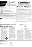
FROM SUPPTYREN
TO TAKE.UFREEI
FII.MTRIP
TOP SAFETY
(PRESS
TO
FORWARD
STOPFILM)
.
REWIND
SWITCH
CAUTION: REVERSE
MUSTBE IN FORWARD
POSITION
l. Releoselop Sofely TriP A
2. Threod film bock to
supply reel
3. Presr buiton B ond
rewind lever
RED
I
"Ovcf rovnd drum"-Aftlr
thrloding film dlrectly
fron rupply rocl lo lop olitql.'tlP rccl, pull rnough
filo troh rupply rccl lo cav.a nom.plqlc below Pro'
itrlor.holor. Stidc ilm dcr round drun' Engogc
,o.o.*Tt tol.. on l.oth ol tound tProckel. Clore
HAND
ATING
CONTROL
D€V/N
PRESS
TO REVERSE
MOIOR LAMP
r---l-l
lronl ond raor lrnllon roll.rt'
RtwrNo sTltl
r-l:
sltENr
To oPER^TE
R^rsErEvER
6)
'
souNDv/
REWIND TOCK RTI,EASE
SEQUENCE
EASYAS I-2.3 TO"THREADIN RED-WHITE-BIUE
I I;"::::":i*"."
lilm hor to mova
"On fo Single SPrcket"
5f
1)
Y"u need o Picture
" T h r o u g hF i l m G o t e '
' SAFETYFIIM IRIPSAUTO'
OR FILMIS DEFECTIVE
THREADED
IF INCORRECNY
MATICAUYSTOP PROJECTOR.CHECKTOOPSAND RAISESTARTINGTEVER
WHITE
"Undcr ringlc drivc rprockcl"-Ihrcod fllm loorcly
bchind middb Sofcty film lriP ond lo undcrridc of
ltolc! wilh
ringlc drive rprociel. Erigcgr !F€*.t
tccth of drirs tpro(kct ond 0lp boltom 0ln rhoc
clorcd. Loop filn oround rnubbcr rollcrr.
Clotq twing-out lenr ond threod filn ocr lop of
driv. iProckQl cngoging tcclh with rprockcf holcr'
flip top nln thoc clo3rd.
SPRING BETTS IN OPERATING POSIION
:
sThrolgh tln golc"-Plocr 0ln In iln got. chonncl
olloring botlon looP th. rlt. ol your Indcr ingcr
lc prcpu round rynchronirolion
*t,.:' ;,
T H A T ' SA L L
BLUE
-.o{-.'1,*-
Proicdor it now lhrcodcd lor Pi(lur! ond round.
FORM 47870-6-662
*.tft*-
Prlntrd In U.$,A.
Ploce rcwind belt on lorge pulley of reor reel orm' Plocr
reversebeh on smoll pulley odding holf-twisl. Toke up belt i
ploced on front reel ormi use smoll pulley for 400'reellorge pulley for reels greoler fhon 400'' Add holf-twist to belt
When replocing cover be sure spring belts ore free of twis
ond kinks. Loop lwo front belts (toke up ond reversel oroun
roised clips on lop ol proiector. The rewind bell is loopet
oround fhe reel orm reloining scrcw.