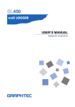
1
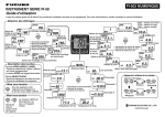
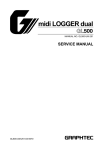
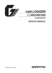
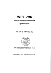
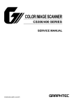
midi LOGGER
200
GL200-UM-251
SERVICE MANUAL
GL200-UM-251-03-9370
HISTORY OF REVISIONS
No. Date issued
Description of revision
1
06.02.14
First Printing
2
06.03.29 Information for the connector of narrow LCD flexible was added.
3
07.05.10 Part number for LCD was corrected.
GL200-UM-251-9370
i
Page
All
3-3
6-1,6-4
Edition
01
02
03
TO ENSURE SAFETY
This Service Manual has been compiled for the purpose of facilitating repair and maintenance of the GL200
midi LOGGER by Graphtec service personnel and other persons who have undergone equivalent technical
training.
Maintenance or repair by unauthorized service personnel is to be strictly avoided. Because the GL200
contains numerous internal components with a high electric potential, such work by unauthorized service
personnel could cause human injury or serious damage to the GL200 midi LOGGER.
GL200-UM-251-9370
ii
CONTENTS
1. CONFIGURATION .................................................................................. 1-1
1.1 Model Configuration .....................................................................................................1-1
1.2 Accessories and Options .............................................................................................1-1
2. UPGRADING THE FIRMWARE ............................................................. 2-1
2.1 How to Upgrade the GL200 Flash ROM from the USB memory device ...................2-1
3. DISASSEMBLY AND REASSEMBLY .................................................... 3-1
3.1
3.2
3.3
3.4
3.5
3.6
3.7
3.8
Notes on Disassembly and Reassembly ....................................................................3-1
Removing the Side Pads...............................................................................................3-1
Disassembling the Top Cover and the Bottom Case Assembly ...............................3-2
Replacing the Main Control Board ..............................................................................3-3
Replacing the Control Panel Board ............................................................................ 3-4
Replacing the LCD........................................................................................................ 3-5
Replacing the AMP Board ........................................................................................... 3-6
Replacing the Input Terminal Board ........................................................................... 3-8
4. SETUP PROCEDURES.......................................................................... 4-1
4.1
4.2
4.3
4.4
Entering the System Setup Menu ................................................................................4-1
AC Line cycle Setting ................................................................................................... 4-4
Performing Setup1 (Voltage Input) ............................................................................. 4-5
Performing Setup2 (Room Temperature Compensation) ......................................... 4-8
5. INSPECTION AND CHECK PROCEDURES ......................................... 5-1
5.1
Inspection and Check Methods ...................................................................................5-1
5.1.1 Measurement Accuracy .......................................................................................................... 5-3
5.1.2 Temperature Accuracy ............................................................................................................ 5-6
6. PARTS LISTS ......................................................................................... 6-1
6.1 Recommended Parts List .............................................................................................6-1
6.2 Parts Lists ......................................................................................................................6-2
6.2.1
6.2.2
6.2.3
6.2.4
6.2.5
Outer Casing ........................................................................................................................... 6-2
Bottom Parts ........................................................................................................................... 6-3
Top Parts ................................................................................................................................. 6-4
Labels...................................................................................................................................... 6-5
Standard Accessories ............................................................................................................. 6-5
7. Block Diagram ....................................................................................... 7-1
GL200-UM-251-9370
iii
1. CONFIGURATION
1. CONFIGURATION
1.1 Model Configuration
GL200
: 10-channel model with color monitor and internal memory
1.2 Accessories and Options
GL200
Unit name
Humidity Sensor
Battery Pack
DC Drive Cable
GL200-UM-251-9370
Model
name
B-530
B-517
B-514
Description
Same as GL450/500
Same as GL450/500
Same as GL450/500
1-1
1. CONFIGURATION
GL200-UM-251-9370
1-2
2. UPGRADING THE FIRMWARE
The version of your GL200’s firmware can be upgraded by rewriting the flash ROM on the pertinent circuit
boards. You can upgrade the firmware by loading the update program to a USB memory device.
2.1 How to Upgrade the GL200 Flash ROM from the USB memory device
Preparations for the upgrade
Firmware :Mxxxa001.G20 ← Main Program file for GL200
:Mxxxa002.G20 ← Main Program file for GL200
(1)
Connect the AC adapter for the GL200.
(2)
Turn on the GL200.
(3)
Copy the two main program files to a USB memory device from the computer.
How to upgrade
(1)
Insert the USB memory device containing the main upgrade program into the GL200's USB port.
(2)
Turn on the GL200 to automatically execute the upgrade program.
(3)
Wait until the display shown below appears or until the beeper sound stops.
Note:
Don't turn off the GL200 until this process is finished.
GL200
The following message will appear on the GL200 display in yellow characters when the upgrade is
complete. Also the beeper will sound for 5 seconds.
“Please Turn Off the Power. I have locked up.”
(4)
Turn off the power to the GL200 when the above message is displayed or when the beeper sound
stops.
(5)
Delete the two main program files from the USB memory device.
This is to avoid upgrading the firmware by mistake.
GL200-UM-251-9370
2-1
3. DISASSEMBLY AND REASSEMBLY
3. DISASSEMBLY AND REASSEMBLY
3.1 Notes on Disassembly and Reassembly
• During disassembly, disconnect the cables from the specified connectors as necessary.
• During reassembly, double-check to ensure that the proper cables have been correctly re-connected to
the pertinent connectors.
• Some areas of the control panel unit possess a high electrical potential, so exercise caution to avoid an
electrical shock.
• When handling the LCD shield and LCD protective plate, be careful not to leave fingerprints or other
marks on them.
3.2 Removing the Side Pads
Disassembly
(1)
Peel off the left and right side pads from the main unit.
Side Pad
Main Unit
Side Pad
Re-assembly
(1)
Push the left and right side pads against the main unit and then install them on the main unit.
GL200-UM-251-9370
3-1
3. DISASSEMBLY AND REASSEMBLY
3.3 Disassembling the Top Cover and the Bottom Case Assembly
Disassembly
(1)
Remove the side pads from the main unit (See Section 3.2).
(2)
Remove the four M2L8 self-tapping screws from the bottom cover.
(3)
Disconnect the connector between the main control board and the AMP board and then remove the top
cover assembly.
Top cover assembly
Bottom case assembly
M2L8 self-tapping screw
Re-assembly
(1)
Re-assemble the top cover assembly and the bottom case assembly in the reverse order in which they
were disassembled.
GL200-UM-251-9370
3-2
3. DISASSEMBLY AND REASSEMBLY
3.4 Replacing the Main Control Board
Disassembly
(1)
Remove the side pads from the main unit (See Section 3.2).
(2)
Disassemble the top cover assembly and the bottom case assembly (See Section 3.3).
(3)
Disconnect the LCD flexible cable from the main control board.
(4)
Remove the two M2L8 self-tapping screws holding the main control board from the top cover assembly.
(5)
Disconnect the connector between the main control board and the control panel board and then remove
the top cover assembly.
M2L8 self-tapping screw
Main control board
Top cover assembly
LCD flexible cable
Control panel board
How to release the narrow LCD flexible cable from the connector
Lift up the black part of the connector using the small flat-head screwdriver.
Lift up this part
Re-assembly
(1)
Re-assemble the main board in the reverse order in which it was disassembled.
(2)
Perform the Setup operations for the GL200 when you replace the main control board.
GL200-UM-251-9370
3-3
3. DISASSEMBLY AND REASSEMBLY
3.5 Replacing the Control Panel Board
Disassembly
(1)
Remove the side pads from the main unit (See Section 3.2).
(2)
Disassemble the top cover assembly and the bottom case assembly (See Section 3.3).
(3)
Remove the main control board (See Section 3.4).
(4)
Remove the four M2L5 self-tapping screws holding the control panel board from the top cover assembly.
(5)
Remove the control panel board from the top cover assembly.
M2L5 self-tapping screw
Control panel board
Top cover assembly
Re-assembly
(1)
Re-assemble the control panel board in the reverse order in which it was disassembled.
GL200-UM-251-9370
3-4
3. DISASSEMBLY AND REASSEMBLY
3.6 Replacing the LCD
Disassembly
(1)
Remove the side pads from the main unit (See Section 3.2).
(2)
Disassemble the top cover assembly and the bottom case assembly (See Section 3.3).
(3)
Remove the main control board (See Section 3.4).
(4)
Remove the M2L5 self-tapping screw holding the LCD bracket and the LCD from the top cover
assembly.
(5)
Remove the LCD from the top cover assembly.
M2L5 self-tapping screw
LCD
LCD Bracket
Top cover assembly
Re-assembly
(1)
Re-assemble the LCD in the reverse order in which it was disassembled.
GL200-UM-251-9370
3-5
3. DISASSEMBLY AND REASSEMBLY
3.7 Replacing the AMP Board
Disassembly
(1)
Remove the side pads from the main unit (See Section 3.2).
(2)
Disassemble the top cover assembly and the bottom case assembly (See Section 3.3).
(3)
Remove the covering seal from the bottom case assembly.
Covering seal
Bottom case assembly
(4)
Remove the five M2L5 self-tapping screws holding the AMP board from the bottom case assembly.
(5)
Remove the AMP board and the input terminal board from the bottom case assembly.
M2L5 self-tapping screw
Input terminal board
AMP board
Bottom case assembly
GL200-UM-251-9370
3-6
3. DISASSEMBLY AND REASSEMBLY
(6)
Remove the input terminal board from the AMP board.
Input terminal board
AMP board
Re-assembly
(1)
Re-assemble the AMP board in the reverse order in which it was disassembled.
(2)
Perform the Setup operations for the GL200 when you replace the AMP board.
GL200-UM-251-9370
3-7
3. DISASSEMBLY AND REASSEMBLY
3.8 Replacing the Input Terminal Board
Disassembly
(1)
Remove the side pads from the main unit (See Section 3.2).
(2)
Disassemble the top cover assembly and the bottom case assembly (See Section 3.3).
(3)
Remove the covering seal from the bottom case assembly.
Covering seal
Bottom case assembly
(4)
Remove the five M2L5 self-tapping screws holding the AMP board from the bottom case assembly.
M2L5 self-tapping screw
Input terminal board
AMP board
Bottom case assembly
(5)
Remove the AMP board and the input terminal board from the bottom case assembly.
GL200-UM-251-9370
3-8
3. DISASSEMBLY AND REASSEMBLY
(6)
Remove the input terminal board from the AMP board.
Input terminal board
AMP board
Re-assembly
(1)
Re-assemble the input terminal board in the reverse order in which it was disassembled.
(2)
Perform the Setup operations for the GL200 when you replace the input terminal board.
GL200-UM-251-9370
3-9
4. SETUP PROCEDURES
4. SETUP PROCEDURES
4.1 Entering the System Setup Menu
(1)
Press the [MENU] key until the “OTHR” menu shown below appears.
(2)
Move the cursor to the “Information” position using the [Direction] keys.
GL200-UM-251-9370
4-1
4. SETUP PROCEDURES
(3)
Press the [ENTER] key to display the “Information” menu shown below.
(4)
Press the [LEFT DOUBLE ARROW Direction] key 10 times in order to display the “Setup” menu shown
below.
(5)
Move the cursor to the “Mode” position using the [Direction] keys.
(6)
Press the [ENTER] key to display the menu from which you can execute the various Setup operations.
Setup mode
Setup1 (Basic)
Setup2 (Room temp.)
(7)
Select the Setup mode using the [Direction] keys, and then press the [ENTER] key.
GL200-UM-251-9370
4-2
4. SETUP PROCEDURES
(8)
Move the cursor to the “Execute Setup” position as shown below.
(9)
Press the [ENTER] key to start the selected Setup operation.
GL200-UM-251-9370
4-3
4. SETUP PROCEDURES
4.2 AC Line cycle Setting
You must set the AC Line cycle setting of the GL200 to the same cycle as that of your AC line before you
perform the Setup1 and Setup2 operations.
How to set the AC line cycle
(1)
Press the [MENU] key until the "OTHR" menu shown below appears.
(2)
Move the cursor to the "AC Line cycle" position using the [Direction] keys.
(3)
Press the [ENTER] key to display the "AC Line cycle" selection menu shown below.
(4)
Select the appropriate cycle for your AC line.
GL200-UM-251-9370
4-4
4. SETUP PROCEDURES
4.3 Performing Setup1 (Voltage Input)
This procedure is required when any part of the AMP board is replaced.
Preparation
• Have a voltage generator on hand that can output voltage up to 50 VDC (four-digit output).
• Mutually connect the ground terminals of the voltage generator and the GL200.
• Set the AC Line cycle setting of the GL200 to the same cycle as that of your AC line.
Wiring connection
Voltage generator
0.00000 V
Connect both ends to GND
FG
Input cable
GND
Connect to CH1
AC adapter
GL200-UM-251-9370
4-5
4. SETUP PROCEDURES
Setup procedure
(1)
As shown in the figure above, connect the output of the voltage generator to the GL200’s CH1 input
terminal.
(2)
Leave the GL200 turned on for at least 30 minutes.
(3)
After entering the System Setup mode, open the Setup menu as shown below.
Specify the AMP Setup conditions as shown below.
Mode
:Setup1 (Basic)
CH
:CH 1
(4)
Move the cursor to the “Execute Setup” position as shown below.
GL200-UM-251-9370
4-6
4. SETUP PROCEDURES
(5)
Press the [ENTER] key to start the Setup1 (Basic) operation.
Message
(6)
The “GND : [START]” message is displayed at the location shown above.
(7)
Input “0.000mV” to the input terminals of channel 1.
(8)
Press the [START] key and then wait until the "20 mV : [START]" message appears.
Specify the voltage generator's output voltage setting to correspond to one of the displayed voltage
ranges in the following table, and then input that voltage to the GL200.
Message
GND
20 mV
50 mV
100 mV
200 mV
500 mV
1V
2V
5V
10 V
20 V
50 V
(9)
Input Voltage
0.000 mV
20.000 mV
50.000 mV
100.000 mV
200.000 mV
500.000 mV
1.000 V
2.000 V
5.000 V
10.000 V
20.000 V
50.000 V
Repeat step (8) by sequentially setting the Measure parameter to 50 mV, 100 mV, 200 mV, 500 mV, 1 V,
2 V, 5 V, 10 V, 20 V and 50 V, and then inputting the corresponding voltage.
(10) When you have finished the Setup operation for 50 V, the "EEPROM : [ENTER]" message appears.
Press the [ENTER] key to begin writing the new Setup data to the EEPROM.
(11) After the setup parameters have been registered to the EEPROM, the display closes and returns to
normal mode.
(12) Turn off the GL200.
This completes the voltage amp setup.
GL200-UM-251-9370
4-7
4. SETUP PROCEDURES
4.4 Performing Setup2 (Room Temperature Compensation)
Preparation
• As shown below, use (T, ø0.32 mm) temperature compensation leads to connect the input terminals to
the 0˚C reference temperature device (Zero controller).
• Set the AC Line cycle setting of the GL200 to the same cycle as that of your AC line.
Wiring connection
Input 0 V for the output side or short the + and - terminals
(T) output side
Connect the GND terminals.
(T) input side
(T) compensation lead
0˚C reference
temperature device
(Zero Controller)
Connect to the CH2, CH4, CH6, CH8 and CH10 input terminals.
AC adapter
CAUTION
Connect each compensation copper lead to a single terminal as shown in the above diagram (parallel
wiring is not permitted).
(1)
As shown in the figure above, connect the inputs of the zero controller to the GL200’s input terminals.
(2)
Leave the GL200 turned on for at least 30 minutes.
GL200-UM-251-9370
4-8
4. SETUP PROCEDURES
(3)
After entering the System Setup mode, open the Setup menu as shown below.
Specify the AMP Setup conditions as shown below.
Mode
:Setup2 (Room temp.)
Area
:Area1
CH
:CH 2
(4)
Move the cursor to the “Execute Setup” position as shown above.
(5)
Press the [ENTER] key to start the Setup2 (Room temp.) operation.
Message
(6)
The “rTemp : [START]” message is displayed at the location shown above.
(7)
Press the [START] key and then wait until the "EEPROM : [ENTER]" message appears.
(8)
Press the [ENTER] key to begin writing the new Setup data to the EEPROM.
(9)
After the setup parameters have been registered to the EEPROM, the display closes and returns to
normal mode.
GL200-UM-251-9370
4-9
4. SETUP PROCEDURES
(10) Re-open the Setup menu as shown below.
Specify the AMP Setup conditions as shown below.
Mode
:Setup2 (Room temp.)
Area
:Area2
CH
:CH 2
(11) Repeat steps (4) to (8) for all the areas up to Area5.
(12) Turn off the GL200.
This completes the Room temp. setup.
Setup flow for the Room temp.
Procedure
Selected area
1
Area 1
2
Area 2
3
Area 3
4
Area 4
5
Area 5
GL200-UM-251-9370
4-10
5. INSPECTION AND CHECK PROCEDURES
5. INSPECTION AND CHECK PROCEDURES
5.1 Inspection and Check Methods
Preparations for inspections and checks
Condition settings file
(1)
:GL2CondVT.CND
← Condition settings for measurement accuracy
Copy the condition settings file to a USB memory device from the computer.
How to load the condition settings file to the GL200 from a USB memory device
(1)
Press the [FILE] key, and then move the cursor to the “Load” position using the [Direction] keys.
(2)
Press the [ENTER] key to display the menu below.
(3)
Move the cursor to the “File Name” position using the [Direction] keys.
GL200-UM-251-9370
5-1
5. INSPECTION AND CHECK PROCEDURES
(4)
Press the [ENTER] key to display the menu shown below.
(5)
Move the cursor to the “USB device” position using the [Direction] keys.
(6)
Press the [ENTER] key to display the menu shown below.
(7)
Specify the condition settings file to execute the various inspection operations.
(8)
Move the cursor to the “OK” position using the [Direction] keys.
(9)
Press the [ENTER] key to load the condition settings file.
GL200-UM-251-9370
5-2
5. INSPECTION AND CHECK PROCEDURES
5.1.1 Measurement Accuracy
Supply the reference voltage or frequency determined for each measurement range, and then check the
voltage accuracy.
Preparation
• Have a voltage generator on hand that can output voltage up to 50 VDC (using four-digit output).
• Mutually connect the ground terminals of the voltage generator and the GL200 prior to initiating
measurement.
Wiring connection
Same wiring connection as Setup1. (See Setup1 procedure)
Setting procedure
(1)
Load the condition settings file "GL2CondVT.CND" from the USB memory device.
Measurement procedure
(1)
Press the [MENU] key to display the menu shown below.
(2)
Move the cursor to the Range position of channel 1.
(3)
Press the [ENTER] key to display the menu shown below, and then select the reference voltage range.
GL200-UM-251-9370
5-3
5. INSPECTION AND CHECK PROCEDURES
(4)
Press the [DISPLAY] key until the menu shown below appears.
(5)
Input the reference voltage for each range according to the table below, and then check that the level of
measurement is within the rating.
Voltage precision ratings
Range
Input voltage
Rating (±0.08%)
20 mV
+20.000 mV
+19.984 mV to +20.016 mV
50 mV
+50.000 mV
+49.96 mV to +50.04 mV
100 mV
+100.00 mV
+99.92 mV to +100.08 mV
200 mV
+200.00 mV
+199.84 mV to +200.16 mV
500 mV
+500.00 mV
+499.6 mV to +500.4 mV
1V
+1.0000 V
+0.9992 V to +1.0008 V
2V
+2.0000 V
+1.9984 V to +2.0016 V
5V
+5.0000 V
+4.996 V to +5.004 V
10 V
+10.0000 V
+9.992 V to +10.008 V
20 V
+20.0000V
+19.984 V to +20.016 V
50 V
+50.000 V
+49.96 V to +50.04 V
This value will change
when the reference voltage
is input from the voltage
generator.
(6)
Press the [START/STOP] key when the input voltage stabilizes.
GL200-UM-251-9370
5-4
5. INSPECTION AND CHECK PROCEDURES
(7)
Wait until the "Finished" message is displayed, and then display the values as shown below.
Message
Confirm that this value is within
the above ratings after data has
been captured.
The data with an automatically
generated file name is captured
to the memory.
(8)
Repeat steps (1) to (7), and then confirm that each value is within the above ratings.
GL200-UM-251-9370
5-5
5. INSPECTION AND CHECK PROCEDURES
5.1.2 Temperature Accuracy
Preparation
• Use (T) and (K) temperature compensation leads to connect a 0˚C reference temperature device (zero
controller) to the GL200 input terminals as shown below.
• As shown below, use copper leads to connect the 0˚C reference temperature device (zero controller) to a
voltage generator that can specify output up to 1µV.
Wiring connection
Voltage generator
0.00000 V
FG
Output side
Connect the GND terminals.
Input side
Compensation lead
AC adapter
0˚C reference
temperature device
(Zero Controller)
Connect (T) compensation leads to the CH2, CH4, CH6, CH8 and CH10 input terminals.
or
Connect (K) compensation leads to the CH3, CH5, CH7 and CH9 input terminals.
Note : The compensation leads should be connected individually. Do not connect in parallel. Connect the
FG of the voltage generator and the AC adapter.
GL200-UM-251-9370
5-6
5. INSPECTION AND CHECK PROCEDURES
Setting procedure
(1)
Load the condition settings file GL2CondVT.CND from the USB memory device.
Measurement procedure (temperature accuracy)
(1)
Connect to the zero controller with the (T) compensation leads.
Connect the (T) compensation leads to the CH2, CH4, CH6, CH8 and CH10 input terminals.
(2)
Use the voltage generator to successively input the reference voltage signal for the 0˚C reference
temperature device (zero controller) according to the table below, then check that the level of
measurement is within the rating.
Input voltage precision ratings (Type T)
Temperature
Input voltage
Standard
0 ˚C
0.000 mV
-0.8 ˚C to +0.8 ˚C
(3)
Connect to the zero controller with the (K) compensation leads.
Connect the (K) compensation leads to the CH3, CH5, CH7 and CH9 input terminals.
(4)
Input the reference voltage signal for the 0˚C reference temperature device (zero controller) according
to the table below, then check that the level of measurement is within the rating.
Input voltage precision ratings (Type K)
Temperature
Input voltage
Standard
0 ˚C
0.000 mV
-1.0 ˚C to +1.0 ˚C
GL200-UM-251-9370
5-7
6. PARTS LISTS
6. PARTS LISTS
6.1 Recommended Parts List
Part No.
790420700
790420701
790420702
790420703
500051951
500052392
500052390
500052418
795450004
562060005
Part Name
Main Control Board for GL200
AMP Board for GL200
Input Terminal Board for GL200
Control Panel Board for GL200
AC Adapter JP
AC Adapter UL
AC Adapter CEE
AC Adapter BS
Battery Pack
LCD, COM35H3125XL
GL200-UM-251-9370
Description
YC-1048GRC1209P
YC-1048GRC1208P
YC-1048GRC1175P
YC-1048GRC1247P
6-1
Q'ty
1
1
1
1
1
1
1
1
1
1
Remarks
Japan
UL
CEE
BS
Same as GL450
6. PARTS LISTS
6.2 Parts Lists
6.2.1 Outer Casing
No.
1
2
3
4
Part No.
604100004
604100014
604100043
604100082
Part Name
Top Cover
Bottom Case
Side Pad
Emblem Plate 200 "GRAPHTEC"
Description
Q'ty
1
1
2
1
Remarks
Outer Casing
3
4
1
2
3
GL200-UM-251-9370
6-2
6. PARTS LISTS
6.2.2 Bottom Parts
No.
1
2
3
4
Part No.
790420701
790420702
604100090
604100023
Part Name
AMP Board
Input Terminal Board
Covering Seal
Battery Cover
Description
Q'ty
1
1
1
1
Remarks
Bottom Parts
2
1
3
4
GL200-UM-251-9370
6-3
6. PARTS LISTS
6.2.3 Top Parts
No.
1
2
3
4
5
6
Part No.
790420700
790420703
604100053
562060005
604100070
604100033
Part Name
Main Control Board
Control Panel Board
Key Switch
LCD, COM35H3125XL
LCD Bracket
IO Panel
Description
Q'ty
1
1
1
1
1
1
Top Parts
6
1
2
3
5
4
GL200-UM-251-9370
6-4
Remarks
6. PARTS LISTS
6.2.4 Labels
No.
1
2
3
4
5
6
Part No.
604100132
604100113
604350801
910990020
604350860
604250801
Part Name
Serial Number Label
Model Name Label GL200
Warning Label
WEEE Label
Warning Label, Battery
CAT Label
Description
Q'ty
1
1
1
1
1
1
Remarks
Q'ty
1
1
1
1
1
1
1
Remarks
Labels
4
3
2
1
6
5
6.2.5 Standard Accessories
No.
1
2
3
4
5
6
7
Part No.
604109101
604109140
604109121
500051951
500052392
500052390
500052418
Part Name
GL200-CDM01M
GL200-UM-851
GL200-UM-901
AC Adapter JP
AC Adapter UL
AC Adapter CEE
AC Adapter BS
GL200-UM-251-9370
Description
CD Manual, Software
Quick Start Manual
Installation Manual
YC-1048GRC1209P
YC-1048GRC1208P
YC-1048GRC1175P
YC-1048GRC1247P
6-5
Japan
UL
CEE
BS
GL200-UM-251-9370
7-1
O
I
Humidity Sensor
+5V Output for
Power Switch
AC Adapter
GL200 Block Diagram
AMP Board
Input Terminal Board
1 ch to 10 ch
Control Panel Board
Main Control Board
Battery Pack
(Option)
Pulse
Logic
Trigger
Alarm
GND
LCD 3.5 inch TFT
USB port B
USB port A
7. BLOCK DIAGRAM
7. Block Diagram