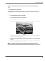
1
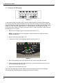
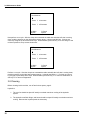
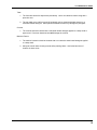
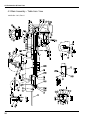
Serial Numbers 032425 & Up
TECHNICAL SERVICE
AND PARTS MANUAL
TITAN 200
PAPER CUTTING
MACHINE
Sold and Serviced by
The Challenge Machinery Company
6125 NortonCenter Drive
Norton Shores, MI 49441-6081 USA
ChallengeMachinery.com
F.200-CT
August 2003
1.0 Introduction
1.0 Introduction
THIS MANUAL is designed to help you get the most from your Challenge equipment. Keep this
manual in a safe, convenient place for quick reference by operators and service personnel.
SAFETY ALERT! This symbol means CAUTION: Personal safety
instructions! Pay special attention to the instructions in bold type. Personal injury may result if the
precautions are not read and followed.
FOR PARTS AND SERVICE contact the Authorized Challenge Dealer from whom you purchased
your machine. Use the illustrations and parts lists at the back of this manual to identify the correct
parts needed. Always give the SERIAL NUMBER and MODEL of your machine to insure the correct
parts are sent as soon as possible.
Challenge® is a registered trademark of The Challenge Machinery Company• 6125 Norton Center Drive • Norton Shores, MI
49441-6081
Copyright© 2003 by The Challenge Machinery Company. All rights reserved. Printed in the U.S.A
2
1.0 Introduction
TABLE OF CONTENTS
1.0 Introduction....................................................................................................................................... 2
2.0 Safety ............................................................................................................................................... 4
2.1 Precautions .................................................................................................................................. 4
2.2 Power Lockout Procedure............................................................................................................ 4
2.3 Warning Label Definitions ............................................................................................................ 5
3.0 Maintenance Guide .......................................................................................................................... 6
3.1 Troubleshooting ........................................................................................................................... 7
3.2 Description of Error Messages..................................................................................................... 8
3.3 Sensor Data Abbreviations .......................................................................................................... 9
3.4 Routine Maintenance ................................................................................................................. 10
3.4.1 Weekly ................................................................................................................................ 10
3.4.2 Monthly ............................................................................................................................... 10
3.4.3 Yearly.................................................................................................................................. 10
3.5 Checking/Changing the Hydraulic Fluid..................................................................................... 10
3.5.1 Recommended Hydraulic Oils ............................................................................................ 11
3.6 Oil and Grease ........................................................................................................................... 12
3.7 Adjustments ............................................................................................................................... 14
3.7.1 Electric Eye Alignment........................................................................................................ 14
3.7.2 Backgauge Gib Adjustments .............................................................................................. 15
3.7.3 Squaring the Backgauge .................................................................................................... 16
3.7.4 Clamp Pressure Adjustment............................................................................................... 17
3.8 Cleaning ..................................................................................................................................... 18
4.0 Schematics & Parts Lists................................................................................................................ 20
4.1 Main Assembly – Front View ..................................................................................................... 20
4.2 Main Assembly – Right Side View ............................................................................................. 22
4.3 Main Assembly – Table Asm. View............................................................................................ 24
4.4 Main Assembly – Tilt Shield / Electric Eyes ............................................................................... 26
4.5 Hydraulic Power Unit – 60 Hz .................................................................................................... 28
4.6 Hydraulic Power Unit – 50 Hz .................................................................................................... 29
4.7 Hydraulic Manifold Assembly & Schematic ............................................................................... 30
4.8 Power Panel Label ..................................................................................................................... 31
4.9 Electrical Schematic – Tilt Shield Machines .............................................................................. 32
4.10 Electrical Schematic – Electric Eye Machines ......................................................................... 34
4.11 Power Panel Assembly ............................................................................................................ 36
4.12 Control Console Assembly....................................................................................................... 38
4.13 Knife Latch Assembly .............................................................................................................. 39
4.14 Line Light Assembly................................................................................................................. 40
4.15 Cut Button Assembly ............................................................................................................... 41
4.16 Fuse Value and Function ......................................................................................................... 42
4.17 Control P.C. Assembly ............................................................................................................. 43
4.18 Electric Eye Assembly ............................................................................................................. 44
4.19 Titan 200 Floor Plan................................................................................................................. 48
5.0 Safety Systems Test ...................................................................................................................... 50
3
2.0 Safety
2.0 Safety
2.1 Precautions
•
•
•
•
•
•
•
•
•
•
•
•
•
•
•
•
This machine is designed for one-person operation. Never operate the machine with more than
one person.
Safe use of this machine is the responsibility of the operator. Use good judgment and common
sense when working with and around this machine.
Read and understand all instructions thoroughly before using the machine. If questions remain,
contact the dealer from which you purchased this machine. Failure to understand the operating
instructions may result in personal injury.
Only trained and authorized people should operate this machine.
DO NOT ALTER SAFETY GUARDS OR DEVICES. They are for your protection. Severe
personal injury may result.
Disconnect power before cleaning or performing maintenance. See Section 2.2 Power Lockout
Procedure.
Observe all caution labels on this machine.
Be sure the cutter is properly grounded.
Be sure there is sufficient power to operate the cutter properly.
Observe all caution plates mounted on this cutter.
Keep foreign objects off table and away from cutter blade.
BE EXTREMELY CAREFUL when handling and changing the cutter knife. Severe lacerations or
dismemberment could result from careless handling procedures.
Keep the floor around the cutter free of trim, debris, oil and grease.
When replacing hydraulic parts, loosen the connections slowly to release pressure. Never loosen
connections with the machine running.
If the cutter sounds or operates unusually, turn it off and consult the troubleshooting section of
this manual. If the problem cannot be corrected, have it checked by a qualified service person.
CRUSH HAZARD, keep hand and fingers from under the clamp when clamping paper. Use
Jogging Aid to load paper, and use the backgauge to push paper out before unloading. DO NOT
REACH UNDER THE KNIFE AND CLAMP AREA!
2.2 Power Lockout Procedure
For maximum safety while making adjustments or repairs to your machine, be sure to disconnect
power to the machine. Disconnect the power plug from its socket
Figure 1 - Main Power Disconnect
4
2.0 Safety
2.3 Warning Label Definitions
The following warning labels are found at various locations on your machine. Read and understand
the meaning of each symbol. If a label is lost from the machine, it should be replaced.
HAZARDOUS AREA
Disconnect power before cleaning, servicing, or making adjustments not requiring
power. Do not alter safety guards or devices; they are for your protection. Replace
all guards. Do not operate with any guards removed.
SHOCK HAZARD
Disconnect power before removing cover. Replace cover before operation.
SHOCK HAZARD
Disconnect power before removing cover. Replace cover before operation.
SINGLE OPERATOR
Do not operate with more than one person.
5
3.0 Maintenance Guide
3.0 Maintenance Guide
NOTICE
The instructions on the following
pages are for the use of trained
service personnel only!
Attempting to perform repair and
replacement procedures without
proper training may cause
machine damage or operator
injury!
PARTS CUSTOMERS: Parts with the express understanding that they are to replace parts
found missing or no longer serviceable on equipment designed and/or manufactured at
Challenge. The Challenge Machinery Company assumes no liability for any modification or
alteration to any Challenge products, and any such modification or alteration to any
Challenge product is not authorized by The Challenge Machinery Company. Any
modification or alteration of any Challenge product will void any remaining warranty.
6
3.0 Maintenance Guide
3.1 Troubleshooting
WON’T START
Fuse Blown.
Power cord disconnected.
Main power switch not turned on.
BACKGAUGE DISPLAY INACCURATE
Preset circuit board malfunction.
Encoder malfunction.
Main circuit board malfunction.
BACKGAUGE DISPLAY INACCURATE - BY CONSTANT AMOUNT
Backgauge needs accuracy adjustment.
Presetter malfunction.
CUT BUTTONS PUSHED - WON’T CUT
Check error codes (page 8).
Obstruction between electric eyes (if equipped).
Guard open (if equipped).
Guard hasn’t been opened since last cut (if equipped).
Hydraulic fluid low.
Main relief valve setting off.
Sequence pressure set wrong.
Cut button defective.
Motor relay defective.
Knife latch solenoid defective.
Knife down coil defective.
Defective directional valve.
Cylinder disconnected from cylinder bracket.
Knife bar dirty or dry, lubricate knife guideways.
Dirt in hydraulic system.
CLAMP STARTS UP BEFORE KNIFE IS UP
Clamp Up Sequence Valve setting incorrect/defective.
CONCAVE CUTTING - ENDS WIDE, CENTER NARROW
Excessive moisture at edges of paper.
CONCAVE CUTTING - VARIATION FROM TOP TO BOTTOM
Soft paper not firmly clamped.
Knife dull or incorrectly grounded.
ERRATIC OPERATION-POWER LOSS
Hydraulic fluid low.
Dirt in hydraulic system.
Oil bypassing piston in cylinder .
Voltage supply is low.
KNIFE DRIFTS DOWN
Knife latch not engaging or damaged.
KNIFE HESITATES OR STALLS
Dull knife.
Main relief valve setting off.
7
3.0 Maintenance Guide
Paper clamped too tight - lower clamp pressure reducer setting.
Cylinder seals worn - leaking pressure.
Hydraulic fluid low.
Voltage supply is low.
KNIFE STARTS DOWN BEFORE CLAMP REACHES TABLE
Knife down sequence valve setting incorrect.
Clamp pressure set too low.
KNIFE WON’T RETURN UP
Solenoid defective.
Limit switch out of adjustment.
Cylinder disconnected from bracket.
Sequence valve misadjusted.
PUMP-MOTOR WON’T SHUT OFF
Knife/Clamp Up Limit switch not activated - readjust.
Motor relay contacts welded.
3.2 Description of Error Messages
Message
Backgauge Failure
Backgauge doesn’t move
Backgauge at Limit
Clamp Down Failure
Backgauge is all the way
forward or backward
Bad program chip
Clamp failed to return to up
position within 7 seconds
Clamp failed to come down
Clamp or Knife Down
Clamp or knife stayed down
DATA IS OUT OF RANGE
The number is outside the limits
of the machine
Motor starter was OFF when it
should have been ON
Motor starter was ON when it
should have been OFF
Latch prox. ON when it should
have been OFF
Cheksum Error
Clamp Up Failure
Motor Starter Failure 1
Motor Starter Failure 0
Knife Latch Failure 1
Knife Latch Failure 0
Knife Down Failure
Knife Up Failure
Knife at Both Limits
8
Description
Latch prox. OFF when it should
have been ON
Knife failed to come down
within 4 seconds
Knife failed to return within 1.17
seconds
Knife up and down prox.
Switches are on at the same
time
Test
Mechanical bind; encoder
failure; main pcboard; blown
fuse
Replace EEPROM
Clamp up sequence valve;
solenoid (cut) valve
Solenoid valves; low voltage,
low pressure
No main pressure; stuck
solenoid valve
Informational error
Defective motor contact switch
Defective motor contact switch
Loose solenoid wire;
mechanical bind; knife up prox.
Switch out of adjustment;
defective prox. Switch
Low main pressure; low
voltage; knife down sequence
valve
Mechanical bind; solenoid (cut)
valve
Prox. Switches; broken knife
bar components
3.0 Maintenance Guide
Message
Description
Lubricate Machine
Lubricate machine alarm
Memory Failed
A memory error occurred during
test
Should only occur during initial
assembly otherwise is an
encoder error
Tried to change a locked
channel
Tried to link two channels
together and the linked channel
is locked
Selected cut position beyond
limits of machine
Backgauge failed to move to
programmed position within +/.oo5
Encoder wires 9 & 10 are
reversed
Memory Locked
Next Channel Locked
Number Outside of Limit
Positioning Error
Remove Obstruction
Obstruction is blocking electric
eyes, or electric eyes are not
functioning properly
When a math operation yields a
negative number
Console key was pressed while
backgauge was moving
Timing error in either up or
down cycled
Sharpen knife alarm
Console Key shorted
Result is Negative
Send Cancelled
Sequence Error
Sharpen Knife
Shorted Key Error
Test
Have machine lubricated
Replace encoder
Operator error; false clamp limit
Mechanical bind; encoder
failure; main pcboard;
leadscrew thrust washers loose;
gibs loose
Remove obstruction, check
alignment of eyes, check all
electric eye connections
Operator error; key board
failure
Low main pressure; any
sequence valve
Have knife sharpened
Operator error; defective
keyboard
** If error codes cannot be reset by depressing the clear key, the power will have to be turned OFF
and ON**
3.3 Sensor Data Abbreviations
Abbreviations
LEFTCUT
RGHTCUT
KNFLAT
HYDMOT R
KNFDWN
Standby
0
0
0
*1
1
Description
Left Cut Button
Right Cut Button
Knife Latch Proximity Switch
Motor Starter Relay Status
Knife Down Proximity Switch
PRESET
1
Preset Sensor
CUTSOL
0
Cut Valve
UNLOAD
0
Unload Valve
KNLATSOL
0
Knife Latch Solenoid
Location
Lower front of table
Lower front of table
Left side of cutter opening
Right side of power panel
Inside of cutter opening,
right side
Rear of cutter, under left
side of table
Solenoid Valve on left side
of manifold
Solenoid Valve* (not in use
yet)
Inside of cutter opening,
left side
9
3.0 Maintenance Guide
CLAMPUP
1
Clamp up Proximity Switch
HYDUP
1
Hyd. Clamp Up Proximity
KNFUP
0
Knife Up Proximity Switch
CUTBTN
EYES / GUARD
HYDMOT O
N.C.
LTLINE
0
1
0
0
1
Cut Button
Electric Eyes OR Front Guard
Hydraulic Motor Relay Output
No Connection
Line Light Output
CBTNLIT
*On when pump is running.
0
Cut Button Light
Inside rear of cutter
opening, left side
At bottom of clamp
cylinder
Inside of cutter opening,
left side
On display console
In front of cutter opening.
Top right side of main pcb
Inside rear cutter opening,
left side
In display console
3.4 Routine Maintenance
DISCONNECT POWER before making any adjustments or lubricating.
See page 4, SAFETY PRECAUTIONS, for Power Lockout Procedure.
This machine should be placed on a regular maintenance schedule. A clean, lubricated machine will
run longer, smoother, cut more accurately, with less downtime and fewer costly repairs. Schedule
lubrication both early in the day and early in the week. This allows the lubricants to work into the
machine. Lubrication at the end of the day or week allows the lubricants to run off without any benefit
to the machine. The following guidelines will help you set up a regular maintenance schedule:
3.4.1 Weekly
Clean — Clean off old, dirty excess grease. Remove the lower front panel cover and clean
accumulated dust off valves, hoses and connections. Built-up dust increases operating temperatures,
which causes premature wear to all hydraulic components.
Hardware — Remove the lower front panel cover, rear panel cover, and top hood to check all nuts
and bolts for tightness. Loose hardware is the cause of most component wear and in the electrical
area could cause short circuits and/or shock.
Hydraulic Fluid — Low fluid level causes excessive heat and wear on the system. Check the fluid
level as described in section 3.5 below.
Oil and Grease — See section 3.6
3.4.2 Monthly
Backgauge Squaring — See section 3.7.3
3.4.3 Yearly
Change Hydraulic Fluid — See section 3.5
3.5 Checking/Changing the Hydraulic Fluid
The hydraulic fluid level should be checked weekly. To check, remove the lower rear cover and
unscrew the cap on top of the tank (Figure 2).
10
3.0 Maintenance Guide
Dip Stick
Figure 2
Fluid level should be at 1/8” from the end of the dip stick (check with dip stick cap screwed in). Add
fluid if necessary but avoid overfilling as this could cause leakage when hot. Replace the rear panel
when finished.
The hydraulic fluid should be changed AT LEAST ONCE-A-YEAR or after every 1,000 hours of
operation. NOTE: Failure to change oil when needed can damage seals in the cylinders, pump, and
valves.
Empty the hydraulic tank and refill with 1 gallon of International Standards Organization Viscosity
Grade 100 (ISO VG 100) rust, oxidation, and foam inhibiting hydraulic fluid (Challenge part no.:
S-1991).
NOTE: NEVER use automatic transmission fluid or brake fluid as a substitute for the correct
hydraulic fluid. A table of various manufacturers and their equivalents is listed below.
3.5.1 Recommended Hydraulic Oils
Use one of the recommended oils or an ISO VG 100 Hydraulic Fluid
equivalent only. Oils other than the recommended type will cause seals and O-rings to deteriorate.
Unsafe operating conditions will result.
Oil Name
Rykon No. 100
Duro AW Oil 465
AW Machine Oil 100
Pacemaker XD No. 100
Super Hydraulic 100
Nuto H-100
Harmony 100 AW
HO 2A Hydraulic Oil
DTE No. 18
Pennzoil AW 100
Magnus A Oil 215
Tellus 100
Energol HLP 100
Industron 100
Sunvis 851 WR
Rando HD 100
Unax AW 100
Distributor
AMOCO
Arco
Chevron
Citgo
Conoco
Exxon
Gulf
Lubriplate
Mobil
Pennzoil
Phillips
Shell
Sohio
Std. Oil
Indiana/Boron
Sun Oil Co.
Texaco
Union Oil Co.
11
3.0 Maintenance Guide
3.6 Oil and Grease
Turn the power off and disconnect the power cord. Open the front guard (if equipped) and open the
top hood for access. Parts requiring oiling are marked with red paint. See figures Figure 3 through
Figure 10 starting on page 12 for oil and grease locations. Figure 3 through Figure 5 require the knife
and clamp be in the up position. Figure 6 through Figure 10 require the knife and clamp be down.
Wipe off any old or excess grease. Use any brand-name type of grease or light oil to lubricate. It
may be necessary to use the supplied grease brush to access some locations. Note: the leadscrew
may be lubricated with grease or oil. Oil has a tendency to run off and must be lubricated more
frequently; grease tends to collect paper dust and must be cleaned off periodically.
Grease
Oil
Figure 3 – Knife Bar Link – L.H. Side, Upper
Figure 4 – Knife Bar Link – R.H. Side, Upper
12
3.0 Maintenance Guide
Figure 5 – Knife Bar
Figure 6 – Knife Bar Link – L.H. Side, Lower
Figure 7 – Knife Bar Link – R.S., Lower
Knife Bar
Knife Cylinder Bracket, Upper
13
3.0 Maintenance Guide
Figure 8 & Figure 9 –Clamp Guides
Figure 10 – Leadscrew and Backgauge Guide
3.7 Adjustments
Several of the following tests require the machine to be operational
for checking and adjusting. Be very careful that tools and other people are clear of moving
parts and that the cutter is not accidentally operated while adjustments are being made.
Whenever working on the machine, disconnect the power and lock it out (see SAFETY
PRECAUTIONS, page 4) unless the directions specifically require the machine to be powered.
3.7.1 Electric Eye Alignment
If your machine is equipped with electric eyes, the alignment can be checked as follows:
Turn on the power switch, and make sure there are no obstructions between the electric eyes.
•
•
14
If the green and yellow lights on the electric eyes are on solid, then the eyes are in proper
alignment.
If the red light is on and the yellow light is off or flashing, then the eyes either blocked or not
aligned properly.
3.0 Maintenance Guide
If alignment is necessary, loosen the screws that attach the electric eye brackets to the table
extensions. Adjust until the green and yellow lights are on solid as described above and tighten
screws.
3.7.2 Backgauge Gib Adjustments
If the backgauge does not stay squared or jumps up and down when jogging paper against it, the
backgauge gib screws are probably loose or worn.
To Adjust:
1. Send the backgauge near the rear of the table.
2. Turn off the power and disconnect the power cord.
3. Remove the leadscrew cover under the table.
4. Loosen the two side gib screws and the bottom nylon guide screws (Figure 11, next page).
Gib Screws
Nylon Guide
Screws
Figure 11
5. Tighten the bottom, nylon guide screws until they just touch the guide. Do not overtighten or
they could cause the backgauge to bind.
6. Similarly, turn the side gib screws in until they just touch the guide. Lock in position with the
jam nuts.
7. Run the backgauge back and forth the length of the table using the backgauge glide control.
Check for any binding. Readjust if necessary.
NOTE: The screws should be tightened to hold the backgauge square against the guide rail.
Excessive tightening will cause the backgauge to bind and cause premature wear of all components.
15
3.0 Maintenance Guide
3.7.3 Squaring the Backgauge
Figure 12
To test if the backgauge is square, place a small lift of paper against the left side of the backgauge
(but not against the side guide) and make a cut. Now, leave the backgauge in the same position, flip
the lift over and push it against the right side of the backgauge (but not against the side guide). Make
another cut to see if any of the paper will trim off. Run two checks, one starting on the left and
moving to the right; the other, moving from the right to the left. If paper is trimmed in either sequence,
the backgauge is out of square.
1. Make sure the backgauge gibs are set properly (see section 3.7.2 ).
NOTE: Gib adjustments are not necessary on initial machine set-up as gibs have been
adjusted at the factory.
2. Remove the rear plexiglass table cover.
3. Loosen the jam nuts on the backgauge adjusting screws (Figure 13).
Adjusting
Screws with
Jam Nuts
Figure 13
4. Back off the adjusting screw on the side that the trim occurred and tighten the other.
5. With the squaring screws tight, make another test. Continue to adjust and test until no trim
occurs when testing either sequence.
6. Replace the rear plexiglass table cover.
Note: Once the backgauge is square, restore power to the machine and check the backgauge
accuracy (see the Titan 200 Operator manual) to make sure it is accurate.
16
3.0 Maintenance Guide
3.7.4 Clamp Pressure Adjustment
Adjust the clamp pressure reducer (Figure 14) to the desired setting. It is factory preset at 800 psi.
Read the gauge with the clamp down and as the knife begins to move down. Loosen the jam nut on
the valve stem. With an allen wrench, turn the stem clockwise to increase pressure and counterclockwise to decrease pressure.
Note: When cutting pressure sensitive paper, you may want to reduce the clamping pressure (400
psi minimum) to prevent marking the paper.
Clamp
Pressure
Reducer
Figure 14
DO NOT set the clamp pressure below 400 psi. Severe lacerations or
dismemberment could result! The knife and clamp system loses sequence at settings below 400 psi
and the knife could come down before the clamp.
3.7.4.1 Optional Electronic Clamp Pressure Control Adjustment
The electronic clamping control option allows the convenience of changing the clamp pressure at the
control console. The pressure is controlled by use of the up and down arrow keys, 0 being the
lowest - 15 the highest; and is indicated in the upper right hand corner of the display.
Note: To turn the electronic clamp control option on or off, enter the Maintenance Mode and choose
Diagnostic. Then choose Electric Clamp and select “ON” or “OFF”.
To adjust the actual clamp pressure maximum and minimum, first make sure the Electric Clamp
option is set to “ON” (see above paragraph). Enter the Maintenance Mode and choose Diagnostic.
Then choose Clamp Adjust, and the screen on the following page should be displayed:
17
3.0 Maintenance Guide
5.000
Set Maximum
>
Press /\ to Increase
Press \/ to Decrease
A) Main
B) Job
C) Send
D) Exit
Now perform a cut cycle. After the clamp has contacted the table and while the knife bar is coming
down, read the pressure on the right hand pressure gauge. It should read 800 psi. If it does not,
correct by using the up and down arrow keys. When finished, press soft-key “D” to exit and go to the
minimum pressure set up screen shown next:
5.000
Set Minumum
>
Press /\ to Increase
Press \/ to Decrease
A) Main
B) Job
C) Send
D) Exit
Perform a cut cycle. After the clamp has contacted the table and while the knife bar is coming down,
read the pressure on the right hand pressure gauge. It should read 400 p.s.i. If it does not, correct
by using the up and down arrow keys. When finished, press soft-key “C” to return to Send Mode, or
soft-key “D” to return to Diagnostics.
3.8 Cleaning
Before cleaning inside machine, turn off and lockout power, page 4.
Hydraulics
1. The vent fan should be wiped off weekly to maintain maximum cooling of the hydraulic
system.
2. The hydraulic manifold, fittings, and hoses should be wiped off weekly to maintain maximum
cooling. Remove then replace panels as necessary.
18
3.0 Maintenance Guide
Table
1. The front table should be wiped down periodically. Use a non-abrasive cleaner along with a
protective wax.
2. The rear table cover and front guard (if equipped) may be cleaned with glass cleaner or a
mild water based detergent. Some petroleum-based solvents may damage the plexiglass.
Console
1. The console should be cleaned with a mild water based detergent applied to a damp cloth or
paper towel. Petroleum based solvents will damage the console.
Machine Exterior
1. The machine’s exterior should be cleaned with a non-abrasive water based detergent applied
to a damp cloth.
2. Always be careful when cleaning around safety warning labels. Use limited amounts of
cleaners in those areas.
19
4.0 Schematics & Parts Lists
4.0 Schematics & Parts Lists
4.1 Main Assembly – Front View
43000 Sht. 1 of 4, Rev. H
20
4.0 Schematics & Parts Lists
Main Assembly – Front View – 43000 Sht. 1 of 4, Rev. H
21
4.0 Schematics & Parts Lists
4.2 Main Assembly – Right Side View
43000 Sht. 2 of 4, Rev. N
22
4.0 Schematics & Parts Lists
Main Assembly – Right Side View – 43000 Sht. 2 of 4, Rev. N
23
4.0 Schematics & Parts Lists
4.3 Main Assembly – Table Asm. View
43000 Sht. 3 of 4, Rev. K
24
4.0 Schematics & Parts Lists
Main Assembly – Table Asm. View – 43000 Sht. 3 of 4, Rev. K
25
4.0 Schematics & Parts Lists
4.4 Main Assembly – Tilt Shield / Electric Eyes
43000 Sht. 4 of 4, Rev. C
26
4.0 Schematics & Parts Lists
Main Assembly – 43000 Sht. 4 of 4, Rev. C
27
4.0 Schematics & Parts Lists
4.5 Hydraulic Power Unit – 60 Hz
H-477-1, Rev. B
28
4.0 Schematics & Parts Lists
4.6 Hydraulic Power Unit – 50 Hz
H-477-2, Rev. A
29
4.0 Schematics & Parts Lists
4.7 Hydraulic Manifold Assembly & Schematic
HH-476-1
30
4.0 Schematics & Parts Lists
4.8 Power Panel Label
S-1781-54, Rev. C
31
4.0 Schematics & Parts Lists
4.9 Electrical Schematic – Tilt Shield Machines
E-2771-2, Rev. B
32
4.0 Schematics & Parts Lists
Electrical Schematic – Tilt Shield Machines, Continued
E-2771-2, Rev. B
33
4.0 Schematics & Parts Lists
4.10 Electrical Schematic – Electric Eye Machines
E-2771-1, Rev. F
34
4.0 Schematics & Parts Lists
Electrical Schematic – Electric Eye Machines, Continued
E-2771-1, Rev. F
35
4.0 Schematics & Parts Lists
4.11 Power Panel Assembly
EE-2765-1, Rev. F
36
4.0 Schematics & Parts Lists
Power Panel Assembly – EE-2765-1, Rev. F
37
4.0 Schematics & Parts Lists
4.12 Control Console Assembly
EE-3035, Rev. A
38
4.0 Schematics & Parts Lists
4.13 Knife Latch Assembly
41120-3, Rev. A
39
4.0 Schematics & Parts Lists
4.14 Line Light Assembly
EE-2779, Rev. B
40
4.0 Schematics & Parts Lists
4.15 Cut Button Assembly
EE-2851-3 Rev. A
41
4.0 Schematics & Parts Lists
4.16 Fuse Value and Function
Location
F1
Transformer/Voltage
230 VAC
Dimension
5mm x 20mm
F2
F3
F4
Fuse Value/Type
Circuit
2A-T
Backgauge
Motor
3.15A-T
Pcb output
5A-T
Line Lights
10A-T
Main – Hot
T1.Secondary
12 VDC
230 VAC
F5
.5A-T
T2 Primary
5mm x 20mm
5mm x 20mm
13/32” x 11/2”
¼” x 1-1/4”
F6
1.25A-T
T1 Primary
¼” x 1-1/4”
F7
10A-T
230 VAC
FL
5A-T
13/32” x 11/2”
5mm x 20mm
T = Time Delay Fuse
42
5V-logic,
preset,
encoder/15vprox.
12v, 24v Pcb
outputs
Main –
Neutral
Backgauge
Motor
230 VAC
4.0 Schematics & Parts Lists
4.17 Control P.C. Assembly
EE-2807-1
43
4.0 Schematics & Parts Lists
4.18 Electric Eye Assembly
K-3030 Sheet 1, Rev. B
44
4.0 Schematics & Parts Lists
Electric Eye Assembly – K-3030 Sheet 1, Rev. B
45
4.0 Schematics & Parts Lists
Electric Eye Assembly – K-3030 Sheet 2, Rev. A
46
4.0 Schematics & Parts Lists
Electric Eye Assembly – K-3030 Sheet 2, Rev. A
47
4.0 Schematics & Parts Lists
4.19 Titan 200 Floor Plan
43000-FP
48
4.0 Schematics & Parts Lists
NOTES
49
5.0 Safety Systems Test
5.0 Safety Systems Test
Machine manufacturer
CHALLENGE
Model
TITAN 200
Serial Number __________________
Frequency of test: THESE TESTS SHOULD BE PERFORMED AT THE BEGINNING OF EACH
WORK DAY.
Turn the power on and press CLEAR to preset the backgauge. Make sure the knife and clamp are in
the up position (if they are not, follow the instructions in this manual to send them up).
Machines with Front Guards:
Test #1: With the front guard open, press the cut buttons. Nothing should happen. If the knife and/or
clamp come down with the front guard open, do not use the machine. Repair or adjustment is
needed.
Test #2: Close the front guard and press the cut buttons. While the clamp or knife is coming down,
open the front guard. The knife and clamp should immediately return to the up position. If they do
not, do not use the machine. Repair or adjustment is needed.
Machines with Electric Eyes:
Test #1: Wave a test object 12mm in diameter between the electric eye beams. The indicator lights
should indicate the eyes are blocked. If they do not, do not use the machine. Repair or adjustment is
needed.
Test #2: If machine equipped with electric eyes, while making a cut, lean into the electric eye beams.
The knife and clamp should immediately return to the up position. If they do not, do not use the
machine. Repair or adjustment is needed.
50
5.0 Safety Systems Test
Please enter date and initials for both tests.
Date
______ ______ ______ ______ ______ ______ ______ ______ ______ ______ ______
Test 1 ______ ______ ______ ______ ______ ______ ______ ______ ______ ______ ______
Test 2 ______ ______ ______ ______ ______ ______ ______ ______ ______ ______ ______
Date
______ ______ ______ ______ ______ ______ ______ ______ ______ ______ ______
Test 1 ______ ______ ______ ______ ______ ______ ______ ______ ______ ______ ______
Test 2 ______ ______ ______ ______ ______ ______ ______ ______ ______ ______ ______
Date
______ ______ ______ ______ ______ ______ ______ ______ ______ ______ ______
Test 1 ______ ______ ______ ______ ______ ______ ______ ______ ______ ______ ______
Test 2 ______ ______ ______ ______ ______ ______ ______ ______ ______ ______ ______
Date
______ ______ ______ ______ ______ ______ ______ ______ ______ ______ ______
Test 1 ______ ______ ______ ______ ______ ______ ______ ______ ______ ______ ______
Test 2 ______ ______ ______ ______ ______ ______ ______ ______ ______ ______ ______
Date
______ ______ ______ ______ ______ ______ ______ ______ ______ ______ ______
Test 1 ______ ______ ______ ______ ______ ______ ______ ______ ______ ______ ______
Test 2 ______ ______ ______ ______ ______ ______ ______ ______ ______ ______ ______
Repairs
_________________________________________
_________________________________________
_________________________________________
_________________________________________
_________________________________________
_________________________________________
_________________________________________
_________________________________________
_________________________________________
_________________________________________
_________________________________________
_________________________________________
_________________________________________
Initials of
Repairer
________
________
________
________
________
________
________
________
________
________
________
________
________
Date
_____________
_____________
_____________
_____________
_____________
_____________
_____________
_____________
_____________
_____________
_____________
_____________
_____________
51