1
AutoLog® GSM-PLC Service manual
AutoLog® GSM-PLC
SETUP, INSTALLATION
&
SERVICE MANUAL
AutoLog® GSM-PLC Service manual v.1.0
1
AutoLog® GSM-PLC Service manual
1.
INSTALLATION AND CONNECTION TO PERSONAL COMPUTER. .............................................. 4
1.2.
1.2.
1.3.
1.4.
OPEN COVER, POWER CONNECTION, PC CONNECTION CABLE ........................................................... 4
PLC LAYOUT ...............................................................................................................................6
CONNECTIONS ............................................................................................................................. 6
SOFTWARE INSTALLATION ............................................................................................................. 9
1.4.1.
1.5.
2.
Creating new project ............................................................................................................................... 9
PROJECT TESTING ..................................................................................................................... 12
AUTOLOG® GSMPROGRAMMER DESCRIPTION ....................................................................... 14
2.1.
2.2.
2.3.
2.4.
2.5.
GENERAL DESCRIPTION .............................................................................................................. 14
MAIN WINDOW ........................................................................................................................... 14
HOW TO CREATE NEW GSM-PLC PROJECT .................................................................................. 14
FILE ......................................................................................................................................... 15
VIEW ........................................................................................................................................ 15
2.5.1.
2.5.2.
2.5.3.
2.5.4.
2.5.5.
2.5.6.
2.5.7.
2.6.
2.7.
2.8.
2.9.
3.
2
Program Editor...................................................................................................................................... 15
Alarm Log.............................................................................................................................................. 16
Phone Book Editor ................................................................................................................................ 17
Ftp Info Editor ....................................................................................................................................... 17
IButton Book Editor ............................................................................................................................... 18
Time Table Editor.................................................................................................................................. 18
Gprs Info Editor..................................................................................................................................... 19
TRANSFER ................................................................................................................................ 19
CONFIGURATION WINDOW ........................................................................................................... 19
OTHERS.................................................................................................................................... 20
PIN-CODE AND PASSWORD ......................................................................................................... 20
SMS PROGRAMMING PROTOCOL FOR GSM-20/16/8/6/4/GW 3.1. SPECIFICATION ................ 22
3.2.
CONFIGURATION COMMANDS............................................................................................ 23
3.2.1
3.2.2
3.2.3.
3.2.4.
3.2.5.
3.2.6.
3.2.7.
3.2.8.
3.3.
GSM number (NUM) ............................................................................................................................. 23
BTN....................................................................................................................................................... 23
Password (PSW)................................................................................................................................... 24
PIN-Code for GSM modem (PIN) ......................................................................................................... 24
GPRS settings (FTP) ............................................................................................................................ 24
FTP settings (FTP)................................................................................................................................ 25
Launching FTP file transfer................................................................................................................... 25
Time table definition (TTBL) ................................................................................................................. 25
I/O-CONTROL COMMAND..................................................................................................... 27
3.3.1.
3.3.2.
3.4.
SET ....................................................................................................................................................... 27
READ .................................................................................................................................................... 27
PROGRAMMING COMMANDS .............................................................................................. 28
3.4.1.
INIT ....................................................................................................................................................... 28
3.4.2.
Condition............................................................................................................................................... 29
Variables and operands in “condition” field ........................................................................................................... 29
3.4.3.
Operation .............................................................................................................................................. 30
3.4.4.
VIEW..................................................................................................................................................... 31
3.4.5.
DEL ....................................................................................................................................................... 31
3.4.6.
RUN ...................................................................................................................................................... 32
3.5.
ALARM CONTROL ................................................................................................................. 32
3.5.1.
3.5.2.
3.6.
ACK....................................................................................................................................................... 32
PRT....................................................................................................................................................... 32
VARIABLES ................................................................................................................................ 33
3.6.1.
3.6.2.
3.6.3.
3.6.4.
3.6.5.
3.6.6.
3.6.7.
3.6.8.
3.6.9.
3.6.10.
3.6.11.
3.6.12.
3.6.13.
3.6.14.
3.6.15.
3.6.16.
3.6.17.
3.6.18.
3.6.19.
3.6.20.
3.7.
Digital output ......................................................................................................................................... 33
Digital input ........................................................................................................................................... 33
Analogue input ...................................................................................................................................... 33
Analogue output.................................................................................................................................... 33
Counter ................................................................................................................................................. 33
Binary memory...................................................................................................................................... 33
Register output...................................................................................................................................... 33
Word memory ....................................................................................................................................... 35
Word pointer ......................................................................................................................................... 35
Date ................................................................................................................................................. 35
Time................................................................................................................................................. 35
Incoming SMS phone number ......................................................................................................... 35
Incoming Call type ........................................................................................................................... 36
$ Self defined messages ................................................................................................................. 36
Pulse variable .................................................................................................................................. 36
AF-variable (Alarm flag)................................................................................................................... 36
Nn SMS-message phone number in phonebook ............................................................................ 37
Tn phone number for phone call ..................................................................................................... 37
CSn Call Status ............................................................................................................................... 37
TCn Timed control ........................................................................................................................... 37
REAL TIME CLOCK ...................................................................................................................... 38
AutoLog® GSM-PLC Service manual v.1.0
AutoLog® GSM-PLC Service manual
3.7.1.
3.8.
Setting the clock.................................................................................................................................... 38
IBUTTON ................................................................................................................................... 38
3.8.1.
3.9.
Reading the iButton .............................................................................................................................. 38
FTP FILE SYSTEM (DATALOGGING) .............................................................................................. 38
3.9.1.
3.9.2.
3.10.
FTP file structure................................................................................................................................... 39
FTP file.................................................................................................................................................. 40
MODBUS SLAVE/MASTER (GSM VER.1.38) ................................................................................. 41
3.10.13.10.2.
3.10.3.
3.10.4.
3.10.5.
3.10.6.
3.11.
3.12.
3.13.
Configuration ................................................................................................................................... 43
RUN LED modes ............................................................................................................................. 43
IMPORTANT NOTES ..................................................................................................................... 43
3.13.1.
3.13.2.
3.13.3.
3.13.4.
3.14.
Some notes of GSM-Programmer ................................................................................................... 43
Trouble shooting.............................................................................................................................. 44
PIN-code setting and SIM-card installing (read before installing) ................................................... 44
DIP-switches.................................................................................................................................... 45
PID CONTROLLERS (NOTICE! USE ALPROWIN.EXE FOR PID SIMULATION) ....................................... 46
3.14.1.
3.14.2.
3.14.3.
Register Variables of Controllers..................................................................................................... 46
Three point controllers..................................................................................................................... 46
Control Algorithm............................................................................................................................. 47
PROGRAM EXAMPLES FOR GSM-PLC ........................................................................................ 48
4.1.
4.2.
4.3.
VARIABLES AND OPERANDS ....................................................................................................... 48
OPERANDS................................................................................................................................ 48
PROGRAMMING FORMATS ........................................................................................................... 48
4.3.1.
4.3.2.
4.4.
4.5.
4.6.
5.
Modbus memory map...................................................................................................................... 41
RO215 - SER2 MODE..................................................................................................................... 41
Modbus memory map for commands 09, 10 ................................................................................... 42
Programming Modbus Master configuration via ALPROWIN.......................................................... 42
Launching Modbus Master conditional messages .......................................................................... 42
Example of configuring SER2 as Modbus master........................................................................... 42
TRANSPARENT MODE ................................................................................................................. 43
PRINCIPLE OF OPERATION ........................................................................................................... 43
3.12.1.
3.12.2.
4.
3
Programming by GSM-phone (basic programming format)................................................................. 48
Programming by GSM-Programmer .................................................................................................... 48
4.3.2.1.
Program Editor ........................................................................................................ 49
4.3.2.2.
AlarmViewer ............................................................................................................ 49
INIATIALIZATION OF GSM-PLC................................................................................................... 49
PRINCIPLES OF PROGRAMMING ................................................................................................... 49
BASIC PROGRAM EXAMPLES ....................................................................................................... 51
ADDITIONAL MODULES ................................................................................................................ 64
AutoLog® GSM-PLC Service manual v.1.0
AutoLog® GSM-PLC Service manual
1.
Installation and connection to personal computer.
1.2.
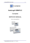
Open cover, power connection, PC connection cable
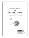
Pic.1 AutoLog GSM4 Unit with power supply
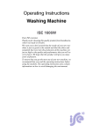
Pic.2 Open the cover with screwdriver (GSM4 Unit on picture)
Pic.3 Open the cover with screwdriver (GSM14 Unit in picture)
AutoLog® GSM-PLC Service manual v.1.0
4
AutoLog® GSM-PLC Service manual
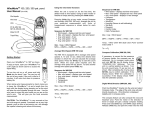
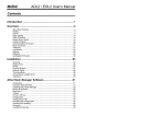
Pic.4 AutoLog GSM4 Unit with IP65 enclosure
Pic.5 Programming cable for GSM-PLCs
AutoLog® GSM-PLC Service manual v.1.0
5
6
AutoLog® GSM-PLC Service manual
1.2.
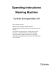
PLC layout
Activity LEDS
RS232
connector
Power and I/O
connector
SIM
card
GSM
module
Pic.6 AutoLog GSM4 unit layout
1.3.
Connections
Connect the programming cable (the narrow part of the cable) to GSM-PLC, RS-232 connector (GSM4
Unit in picture):
AutoLog® GSM-PLC Service manual v.1.0
AutoLog® GSM-PLC Service manual
Connect the programming cable also to computer
(to COM port 1 or 2):
Check that power supply (12-24 VDC) has been connected to GSM-PLC
(GSM4 Unit in picture):
GSM4: Check jumpers / DIP switch settings
Programming setting for GSM4: JP1_3 >> OFF
(GSM4 Unit in picture and table for GSM4)
AutoLog® GSM-PLC Service manual v.1.0
7
8
AutoLog® GSM-PLC Service manual
DIP switch table for GSM14 and GSM20:
JP1
ON
OFF
1
Enable calibration
Disable calibration
3
Connection to modem
Connection to RS232
4
Data memory cleared when
controller is switched on
Data memory retained
during power failure
5
EEPROM not write protected
EEPROM write protected
2
DIP switch table for GSM14 and GSM20:
DIP
ON
OFF
1
EEPROM not write protected
EEPROM write protected
2
Enable calibration
Disable calibration
5
Data memory cleared when
controller is switched on
Data memory retained
during power failure
Connect battery (if you need it).
NOTICE !: GSM-PLC does not start only with battery.
Connect power supply to electrical network
AutoLog® GSM-PLC Service manual v.1.0
AutoLog® GSM-PLC Service manual
1.4.
Software installation
Setup GsmProgrammer from CD to computer
Create directory for GsmProgrammer (E.g. C:\program files\GsmProgrammer).
Copy GsmProgrammer.exe into this directory.
Start GsmProgrammer.exe
Connect Programming cable between PC (COM-port 1 or 2) and GSM-PLC (RS-232 / GSMmodem-connector).
Connect power supply (10…30 V) to GSM-PLC.
Now you can program the application program.
1.4.1.
Creating new project
Create new application program. File >> New:
Give name: HELLO_WORLD >> Save:
AutoLog® GSM-PLC Service manual v.1.0
9
10
AutoLog® GSM-PLC Service manual
Define configuration settings: Transfer >> Config
COM port selection:
•
•
•
•
•
•
•
Com Port 1 or 2 (The programming cable plug)
Baud Rate (always 9600)
No. Program Lines (Set always maximum=100/255 depending of PLC type)
PLC PIN Code (HAVE TO BE ALWAYS SIMILAR WITH SIM CARD) = DO NOT INSERT SIM
CARD BEFORE THAT SETTING IS O.K. (Default is 0000).
Own Phone number is needed if programming performs through GSM network.
Put any number to this place.
Select Modem Type: Direct connection (or GSM Modem)
Press OK
After making correct configuration, this button (Read Back button) should be active
Select Compile >> Compile and you get this little window:
Press OK >>> Now all buttons are active it means that connection from computer to GSM-PLC is active:
Open View >> Source Code
You will get Program Editor. Program your first application to this editor:
‘DI1=1’ “HELLO WORLD” 0
AutoLog® GSM-PLC Service manual v.1.0
11
AutoLog® GSM-PLC Service manual
When digital input 1 is true, send HELLO WORLD message to number 0 (place 0 in Phone Book):
Open View >> Phone Book
You get Phone Book Editor:
•
•
First row is telephone number 0 = place 0.
Second row is telephone number 1 = place 1. Etc...
Put your mobile phone number to place 0.
You can put comments after “;” character in any line.
Transfer application program to GSM-PLC by pushing “Transfer >> Transfer Project”
AutoLog® GSM-PLC Service manual v.1.0
AutoLog® GSM-PLC Service manual
12
You should get this window, press OK
Now you have to Start GSM-PLC. You have two choices:
First: Press green “Start PLC” button.
Second: Open View >> Alarm Log >> write: RUN >> Press Enter.
Than you will receive the message: #RUNNING in Alarm Log window
Also “RUN” LED of GSM-PLC start blinking.
You can test this “HELLO_WORLD” application with Alarm Log window:
Activate digital input 1, after that HELLO WORLD message should appear in Alarm Log window.
Now you can do this test also via GSM network.
1.5.
Project testing
GSM4 Unit: Switch power off and insert SIM card (see layout picture). Remember that PIN code must be
similar in SIM card and in GSM-PLC (default PIN code setting = 0000).
Check again also jumper settings, JP1_3 must be ON.
Connect power on and check RX, TX, RUN and SERV leds, they should blink.
AutoLog® GSM-PLC Service manual v.1.0
AutoLog® GSM-PLC Service manual
13
GSM14/GSM20: Switch power off and insert SIM cart. Remember that PIN code have to be similar in SIM
card and in GSM-PLC. Connect GSM modem back to PLC (short cable) :
Connect power, switch it on and check that “RX”, “TX”, “RUN” and “H1” LEDs will blink.
NOW YOU CAN TEST THE APPLICATION PROGRAM VIA GSM NETWORK.
If you have the control panel, connect it to I2C connector (GSM14 Unit in picture):
On this step hardware and software configuration of AutoLog GSM PLC is finished. You can
proceed to programming application specified instructions.
AutoLog® GSM-PLC Service manual v.1.0
AutoLog® GSM-PLC Service manual
2.
2.1.
14
AutoLog® GsmProgrammer description
General description
GsmProgrammer is Windows 95, 98, NT, 2000, XP compatible configuration program for Autolog® GSM PLCs. Configuration program is used to write, transfer and debug application programs for GSM-PLC.
GsmProgrammer allows all data in GSM-PLC to be monitored through the debug monitor.
In the following sections we describe main features of GsmProgrammer.
2.2.
Main window
After GsmProgrammer is started, you will see the following kind of view. In the main window you can
define password for GSM-PLC, PIN-code for SIM-card used in GSM-PLC and also PC’s own phone
number (This is needed if you need to transfer application to GSM-PLC via GSM network).
In case if most icons are inactive (gray), there is no connection to GSM-PLC or file transfer is in progress.
Programmer status is visible at the bottom of the main window. If there is no connection to GSM-PLC,
check the serial channel settings, serial cable connection and PIN-code. From the Serial channel settings
you can also select what kind of connection is used between PC and GSM-PLC; Direct cable connection
or GSM-network. If you are using GSM network, you will need GSM-modem also connected to PC.
There are following main parts of GSM-PLC “Main Window”
Menu Bar:
Toolbar:
Main page:
2.3.
How to create new GSM-PLC project
To start new GSM-PLC project user can use command menu of GSM-PLC: Select File, then New, after
this a dialog box will open and user will be able to select the folder where the project data should be
stored and which is the project name. After this the Save-button of the dialog box should be clicked.
The second possibility to create a new project is to click New project-button:
on the button set of GsmProgrammer.
Now user must click Config button:
Or in command menu select Transfer, then Config, to set correct configuration.
AutoLog® GSM-PLC Service manual v.1.0
AutoLog® GSM-PLC Service manual
2.4.
15
File
To access the “File” menu commands, click on “File” menu item.
•
•
•
•
2.5.
“New” command is used to create the new GSM-PLC project.
“Open” command is used to open the saved GSM-PLC project.
“Save” command is used to save the GSM-PLC project.
“Reopen” command is used to open one of the recently saved projects.
View
In the main window under the View menu you can select active editors.
Source Code, Alarm Log and Phone Book.
Selecting ”Source Code” you can activate Program Editor window.
Selecting ”Alarm Log” you activate Alarm Log window (Debugger).
Phone book editor activates by selecting ”Phone Book”.
Also available: “IButton Book” Editor, “Ftp Info” Editor, “Time Table” Editor, “Gprs Info” Editor.
2.5.1.
Program Editor
Program Editor window is used to write application programs. Program is written in instruction list format.
Maximum program size is 100 lines (255 lines with AutoLog GSM-20). You can write remarks with “;”
character.
User may use these buttons for transfer, verify and read back program file (*.PRG)
AutoLog® GSM-PLC Service manual v.1.0
16
AutoLog® GSM-PLC Service manual
2.5.2.
Alarm Log
Alarm Log window is used to check SMS-messages that GSM-PLC sends out. In case there is a notation
error in application program, line with errors can be seen in this window. Also debugging the program is
easy to do using Alarm Log.
There is also window where you can send SMS messages or call to GSM-PLC.
application program you can set/read any variable in GSM-PLC through this window.
While testing the
It is also possible to program the GSM-PLC using Alarm Log. E.g. if there is one program line you wish to
add or change, you can send that line using Alarm Log instead of transferring the whole program. Editing
program stops the program execution. Remember to start new program by sending RUN command or
pressing green RUN button in the main window.
If user wants to send command to GSM-PLC, user must manually enter message and
press “Enter” or click on a Send-button.
If user want to send ACK command to GSM-PLC, he must click on Ack button.
Message box will be displayed:
User can add the program line, which has to be acknowledged and then press OK button.
User may load or save Alarm file (*.LOG) using these buttons.
User can simulate calls (voice, data, fax) to GSM-PLC using this button.
AutoLog® GSM-PLC Service manual v.1.0
AutoLog® GSM-PLC Service manual
2.5.3.
17
Phone Book Editor
Phone Book Editor is used to define phone numbers to where GSM-PLC will send messages (Alarms,
reports) or calls. There can be max. 100 phone numbers (255 phone numbers in AutoLog GSM-20). In
application program these phone numbers are referred using line number. Try numbers with or without
country code (some properties work only with country code and some without, but usually properties work
with both, that depend on the used GSM operator / SIM card).
User may use next buttons for transfer, verify and read back phone book file (*.PHF).
2.5.4.
Ftp Info Editor
The Ftp Info Editor can be used only with AutoLog GSM-20 + GPRS modem.
FTP Configuration settings:
Number Of Files None/1/2/4/8 (None disables FTP supporting in PLC)
Ftp Server
Server IP address in dot form
PLC ID
8 HEX symbols
Ftp Path
Path on server to store files (128 characters max)
(By default it is the application project folder)
Ftp Password
Password for Ftp login (98 characters max)
If password doesn’t exists “anonymous” login will be used
When PLC sends file using iChip commands, programmer receives this file and stores it into current
project directory. Notification of receiving file is adding to Alarm Log in following format:
21:15:35 17-07-2003, Received file, FFFFFFFF10307141804, 542 bytes
FFFFFFFF10307141804
542 bytes
File name
File length
Ftp file can be opened with FileModifcation_FTP.xls
AutoLog® GSM-PLC Service manual v.1.0
AutoLog® GSM-PLC Service manual
2.5.5.
IButton Book Editor
The IButton Book Editor can be used only with AutoLog GSM-20.
Amount of Ibuttons can be maximum 256.
IButton representation format:
14 HEX symbols (MUST BE IN UPPER CASE!)
SSSSSSSSSSSSFF
S -- Serial Number
F – Family Code
Ibutton can contain wildcards (“?”).
2.5.6.
Time Table Editor
The Time Table Editor can be used only with AutoLog GSM-20.
Amount of times can be maximum 256.
AutoLog® GSM-PLC Service manual v.1.0
18
AutoLog® GSM-PLC Service manual
2.5.7.
19
Gprs Info Editor
Needed settings with the fixed IP address are:
Modem extra settings depend on GSM/GPRS operator:
Examples:
Finland, Sonera/Elisa:
Sweden, Telia:
2.6.
AT+CGDCONT=1,”IP”,”internet”
AT+CGDCONT=1,”IP”,”online.telia.se”
Transfer
In the main window under Transfer menu is located three file transfer options. These are Transfer Project,
Verify Project and Read Back Project. Also “Program Editor” - and “Phone Book Editor” windows have
Transfer menus.
Transfer Project downloads the whole project (application program and phone book etc.) to GSM-PLC.
Verify Project uploads the project from GSM-PLC and compares project to one that is active in the
programmer.
Read Back is used to upload project in GSM-PLC to GsmProgrammer.
Program Editor- and Phone Book Editor window ”transfer” options can be used when you need to transfer
only either part of the project.
2.7.
Configuration window
The Configuration window is used to set up communication and other features. These are COM port,
Baud rate (9600bit/s), Program Lines (100/256), Numbers (100/256), IButtons (100/256), Times
(100/256), Modem type, PC modem number, GSM-PLC PIN code and Own Phone Number. It is
recommended that user use always the maximum amount (100/256) of Lines, Numbers, Ibuttons and
Times.
AutoLog® GSM-PLC Service manual v.1.0
AutoLog® GSM-PLC Service manual
2.8.
20
Others
Button for Load GSM-PLC Project.
Button for Save GSM-PLC Project.
Button for Create New GSM-PLC Project.
Button for Compile GSM-PLC Project.
Button for Set Configurations.
Transfer Project, Verify Project, Read Back Project
RUN button for start running GSM-PLC application.
2.9.
PIN-code and password
The main page contains next fields:
PLC Type support:
OLD
(PLC ID RO39=0)
TGSM4 RO39=26
GSM14 RO39=20
GSM20 RO39=10
MODEM TYPE to inform user about the type of connection with GSM-PLC: “Direct connection” or “Gsm
Modem”.
OWN PHONE NUMBER informs user about the current phone number.
GSM-PLC PIN CODE allows user to edit PIN Code and change it in GSM-PLC after “Change” button is
pressed.
There are 2 message boxes may be displayed after GSM-PLC PIN CODE is changed:
If PIN Code has not digits after editing, next message box will be displayed:
AutoLog® GSM-PLC Service manual v.1.0
AutoLog® GSM-PLC Service manual
21
GSM-PLC PASSWORD allows user to edit Password code and change it in GSM-PLC after “Change”button is pressed.
There are 2 message boxes may be displayed after it:
If Password code has no digits after editing, next message box will be displayed:
To change GSM-PLC Password user must change digits only in right field (1234 – new GSM-PLC
password),
Left field contains the current PLC Password:
After “Change”-button is pressed and when GSM-PLC successfully changed password, will be displayed
next:
COM STATUS INFORMATION informs user about COM number, baud rate and state of communication.
If GSM-PLC or modem is not connected to PC, next status will be displayed (halted):
In the process of initialization, the status will be displayed as:
After completion of initialization the status will be displayed as:
FILE NAME informs user about the name of a current project file.
AutoLog® GSM-PLC Service manual v.1.0
AutoLog® GSM-PLC Service manual
3.
SMS Programming Protocol for GSM-20/16/8/6/4/GW
3.1.
Specification
-
-
-
22
This protocol is used to create an easy way to program PLC / Small I/O-device using SMSmessages.
One SMS-message is max.115 characters long. There can be several commands in one
SMS-message.
Phone number is max. 16 characters.
SMS-message must not end in the middle of command.
When a command line is sent to GSM-PLC, it checks the incoming message format. If GSMPLC found an error from message, it will send back the whole message, marking the error
with “???”
GSM-PLC stops program execution after receiving program modify command (INIT or DEL).
GSM-PLC must be started with RUN instruction after program editing.
Total amount of variables is defined by the hardware.
Variable type ALL can be used, when user wants to point all inputs/outputs or symbolic links.
Variable “ALL” can be referred as “A”.
Start of SMS-message to GSM-PLC starts always with password and ends to *-character.
Program line can contain condition and multiple actions but only one SMS-message
sending.
There can be only one timer function / program line.
Action can be either SMS-message or PLC-operation.
Field separation mark is a SPACE or multiple spaces or COMMA(‘,’).
Text-field is separated with “ “
Condition field is separated with ‘ ‘
Response from GSM-PLC starts always with #-character.
For alarm messages #-character + line number in the beginning of message means that
ACKNOWLEDGEMENT is needed.
Program line fields are separated by spaces (“ “) or comma sign (“,”)
Transmission uses same format as received message.
GSM-PLC will automatically initialise GSM after power-up.
Length of password always 4 digits.
Commands may be as full word or first letter:
NUM = N
INIT = I
PSW = PSW because we also have PIN instruction (so we can not use P for both).
AutoLog® GSM-PLC Service manual v.1.0
23
AutoLog® GSM-PLC Service manual
3.2.
CONFIGURATION COMMANDS
3.2.1
GSM number (NUM)
Define GSM-number NOTICE! This command stops the application program execution!
PLC must be started with RUN-command
Delete GSM-number
Read GSM-number
Format:
Password NUM i=zzzzzzz* ; define GSM number
Password NUM i=*
; delete GSM number
Password NUM i?*
; read GSM number
NUM
i
zzzzzzz
?
*
A
FCN
ID number
GSM number
Request
End of message
All
Examples:
Query:
Response:
1234 NUM 1=+358953063153*
#NUM 1=+358953063153
; define phone number[1]
Query:
Response:
1234 NUM A=*
#ALL NUM DELETED
; remove all phone numbers
Query:
Response:
1234 NUM 0?*
#NUM 0=+358953063153
; read phone number[0]
Query:
Response:
1234 NUM A?*
; ask all phone numbers from PLC
#NUM A=empty
; if no phone numbers or
#NUM 0=+358053063153 NUM 1=+358953063154*
3.2.2
BTN
•
•
•
Format:
Define Ibutton serial number
Delete Ibutton serial number
Read Ibutton serial number
Password BTN i=zzzzzzz* ; Define GSM number
Password BTN i=*
; Delete GSM number
Password BTN i?*
; Read GSM number
Password
BTN
i
zzzzzzz
?
*
A
FCN
ID number
Ibutton serial number
Request
End of message
All
Examples:
Query:
Response:
1234 BTN 1=0800446A * ; Define Serial number[1]
#NUM 1=0800446A
Query:
Response:
1234 BTN A=*
#ALL NUM DELETED
; Remove all Serial numbers
Query:
Response:
1234 BTN 0?*
#NUM 0=+358953063153
; Read Serial number[0]
Query:
Response:
1234 BTN A?*
; Ask all Serial numbers from PLC
#NUM A=empty
; If no phone numbers or
#NUM 0=0800446A NUM 1=045D6A88*
AutoLog® GSM-PLC Service manual v.1.0
24
AutoLog® GSM-PLC Service manual
3.2.3.
Password (PSW)
•
Format:
Define password
Password PSW MMMM MMMM*
PSW
function
MMMM new password
Examples:
Query:
Response:
3.2.4.
1234 PSW 4321 4321*
# PSW OK
# PSW BAD
; password changed successfully
; if password didn't change!
PIN-Code for GSM modem (PIN)
•
Format:
Define PIN-code
Password PIN NNNN NNNN*
PIN
function
NNNN new PIN-code
Examples:
Query:
Response:
3.2.5.
4321 PIN 3322 3322*
# PIN OK
; PIN-code changed successfully
# PIN BAD
; mistake in changing PIN code!
GPRS settings (FTP)
•
Defines the GPRS system provider settings to MODEM
Format:
GPRS=M,P,[aaa.aaa.aaa.aaa],[bbb.bbb.bbb.bbb],[username],[Password],
["at+cgdcont=1,"IP","internet"]
[ ] - field may be empty
M - PPP Authentication Method
1 Use PAP authentication.
2 Use CHAP authentication.
P – Phone number:
1 - "*99***1#"
2 - "*99#"
aaa.aaa.aaa.aaa – DNS1
bbb.bbb.bbb.bbb – DNS2
Examples:
SONERA & Elisa uses following GPRS settings
AT+CGDCONT=1,"IP","internet"
So command in whole for Sonera SIM card:
GPRS =1,1,,,,,AT+CGDCONT=1,"IP","internet"
WaveCom modem WITHOUT Ichip:
GPRS =1,1,,,,, internet
for set APN parameters enter in GSM PLC Programmer GPRS info:
ISP User name/APN User name
AutoLog® GSM-PLC Service manual v.1.0
25
AutoLog® GSM-PLC Service manual
ISP Password/APN Password
Modem extra settings/APN server name
3.2.6.
FTP settings (FTP)
Note! For this feature you need GPRS modem and iChip unit or Wavecom GSM modem with
TCP/IP stack support
•
Define FTP settings
Format:
Password FTP=n,IP,Path,PLC ID,<Password>
n
IP
Path
PLC ID
Password
number of files (1, 2, 4, 8 ;1x256k, 2x128k, 4x64k, 8x32k)
Server IP address xxx.xxx.xxx.xxx
Path to server to store files (128 char max.)
8 Hex symbols
Password for login. If password doesn’t exist, “anonymous” login will
be used (98 char max.)
Examples:
3.2.7.
Set FTP parameters:
Response:
4321 FTP<sp>=8,123.123.123.123,root/ffa,00112233
#FTP=8,123.123.123.123,\ffa,00112233
Read FTP parameters:
Response:
4321 FTP ?
#FTP=8,123.123.123.123,\ffa,00112233
or #FTP = EMPTY
Delete FTP parameters:
Response:
4321 FTP =
#FTP=EMPTY
Launching FTP file transfer
There are two RO’s used to control FTP file transfer
RO37 = FTP command / Status register
RO38 = File number
Command RO37 = 1- Request to send file defined in RO38
RO37 status:
2
128
129
130
131
132
133
134
135
136
137
139
file succesfully sent
invalid file number
file not used in application program
file empty
iChip not connected
can’t open FTP session
wrong path
can’t store file
can’t delete File
can’t send File
can’t close File
modem doesn’t support FTP
RO38 – file number:
0…7 or 8…15 for deleting file after succesful transmission
3.2.8.
Time table definition (TTBL)
•
Format:
Time table definition command
Password TTBL n=m,s,t,d
AutoLog® GSM-PLC Service manual v.1.0
26
AutoLog® GSM-PLC Service manual
n
m
s
t
d
Line number 0..255
TC variable address (0..127)
Status 0-OFF, 1-ON
Time hh:mm 00:00 to 23:45 (Table is checked every 15 minutes)
Date/weekday dd.mm/1(Monday)-7(Saturday). Can be left empty.
Conditions for weekday:
A-B
= from day a to day B
A= Day A only
A,B
=
A=B is invalid
1-7, 4-1 are invalid definitions
Either t, d or both must be defined in control line
There can be tot. 256 definition lines for ON & OFF controls for different TC variables.
These lines can be freely used for as many as 256 TC variables.
The line order for TC is important. User should define first normal ON and OFF controls and
after that the exceptions. The last active line defines the state of the TC.
E.g
TTBL 0= 5,1,08:30,1-5
;TC5 is set to ON at 8:30 am from Monday to Friday
TTBL 1= 5,0,16:30,1-5
;TC5 is set to OFF at 16:30 am from Monday to Friday
st
TTBL 2= 5,0,00:00,24.12;TC5 is set to OFF at 24.12 (if this line is the 1 line of the TC5 and
24.12 is Wednesday, lines to follow would over write this control)
Time control function is executed every 15 minutes.
Note! If PLC is not running when TTBL line should trigger TC to be active, control will not take
place after power returns.
TC2
TC0
TC1
ON, 08:00,Mo-Fr
ON,22:00 ,Fr-Su
ON, 18:00,We,Sa
ON, 06:00
OFF, 03:00,Sa-Mo
OFF, 22:00,We,Sa
OFF, 20:00
ON,07:30 ,Mo-Fr
ON,17:00, Fr
OFF,21:00 ,Fr
OFF, 17:00,Mo-Fr
OFF, ,24.12
OFF, ,1.1
TC3
OFF,08:00 ,Mo-Fr
ON, 12:00,24.12
OFF, 21:00,24.12
Examples:
Query:
Response:
1234 TTBL 0=10,1,08:00,1-5*
; define ON control for unit TC10
#TTBL 0=10,1,08:00,1-5 ; to line 0 (out of 256)
Query:
Response:
1234 TTBL 0=*
#TTBL 0 DELETED
; remove control line from time table
Query:
Response:
1234 TTBL 0?*
#TTBL 0=10,1,08:00,1-5*
; read line 0
Query:
Response:
1234 TTBL A?*
; ask all TC definitions from PLC
#TTBL A=empty
; if no TC’s or
#TTBL 0=10,1,08:00,1-5 TTBL 1=10,0,16:00,1-5 TTBL 2=10,0,,24.12*
Notice! Time control tables can be at any order with in time table, so if you need to add new exception line
for time control n, you can insert this line at the first available location AFTER normal ON/OFF control.
Timetable row
TTBL
0
Time control block
5
Action
0-OFF 1-ON
1
AutoLog® GSM-PLC Service manual v.1.0
Time
Date/Weekday
06:00
1-5 (Mo-Fr)
27
AutoLog® GSM-PLC Service manual
1
20
100
150
5
5
5
5
0
0
0
0
18:00
1-5 (Mo-Fr)
1.6
24.12
31.12
Eg. Using TC for changing the Summer / Winter time
TTBL 0 = 0,1,03:00,14.04 ;use table 0; set TC0 active at Spring
TTBL 0 = 0,0,04:00,25.09 ;reset TC0 at Autumn
In application program set device to send time correction message to itself
Line 0: TC0=1 “0000 TIME=0400,%RO250,%RO249%RO248*”*
;when TC0 goes active send new time to PLC
Line 1: TC0=0 “0000 TIME=0300,%RO250,%RO249%RO248*”*
;when TC0 goes inactive send new time to PLC
Q: When we change time back one hour, doesn’t the unit send the same message after time gets
four o’clock?
A: After one hour the the message is not resent because the TC0 is already 0 so negative
derivation wont take place. The only place when TC0 is set active is one 15 minute window at
Spring.
3.3.
I/O-CONTROL COMMAND
3.3.1.
SET
•
Define output status
Format:
Password SET var=0/1*
SET
Var
function
DOn=x
CNn=xxx
Mn=x
WGn=xxxxx
WMn=xxxxx
ROn=xxx
digital output, where n defines output number
counter n
memory n
PID controller variable n
word memory n
configuration register n
Examples:
3.3.2.
Query:
Response:
4321 SET DO1=0*
#DO1=0
Query:
Response:
4321 SET WM100=1300* ; set counters alarm level to 1300
#WM100=1300
; program could be: 'CN0>WM100' DO0=1
READ
•
Format:
Read I/O-status
Password READ var*
READ
Var
function
DOn
Digital Output, where n defines output number
DIn
Digital Input
AIn
Analoque Input
AOn
Analogue Output
CNn
Counter n
Mn
Memory n
WGn
16-bit PID controller variable n
WMn 16-bit variable n
ROn
Special function register
AFn
Alarm Flag n
CSn
Call Status n
AutoLog® GSM-PLC Service manual v.1.0
AutoLog® GSM-PLC Service manual
Examples:
Query:
Response:
4321 READ DO2*
#DO2=0
Query:
Response:
4321 READ RO100*
#RO100=14
Query:
Response:
4321 READ AI0*
#AI0=3000
3.4.
PROGRAMMING COMMANDS
3.4.1.
INIT
•
•
Format:
Define control lines
NOTICE! This command stops the application program execution!
PLC must be started with RUN-command
a)
b)
password INIT line ’Condition’ Action*
password INIT line ’Condition’ ”text” num [alarm reset time]*
Examples:
; Send message "ALARM" to ph. number 1 when DI0 goes active
Query:
4321 INIT 3 ’DI0=1’ ”ALARM” 1*
Response:
#Line3:’DI0=1’ ”ALARM” 1
; Set output0 active when input 0 =1 and input 1 = 0
Query:
4321 INIT 7 ’DI0&!DI1’ DO0*
Response:
#Line7: ’DI0&!DI1’ DO0
; Turn output 0 off after it has been active for 5 seconds
Query:
4321 INIT 9 ’DO1S5’ DO1=0*
Response:
#Line9: ’DO1S5’ DO1=0
; If DI2 XOR DI3 = 1, set output 0; active for 3 seconds
Query:
4321 INIT 10 ‘DI2XDI3’ DO0S3*
Response:
#Line10: ‘DI2XDI3’ DO0S3
; When input 0 changes to 1, send counter value 2 to ph. number 1
Query:
4321 INIT 11 ‘DI0=1’ “Counter:%CN2” 1*
Response:
#Line11: ‘DI0=1’ “Counter %CN2”
; Display counter value to display once/minute
Query:
4321 INIT ‘P2’ “Counter: %CN0” 255*
Response:
#Line12: ‘P2’ “Counter: %CN0”
; If incoming SMS message ="$STATUS*", set flag
Query:
4321 INIT ‘($STATUS)’ M0*
Response:
#Line12: ‘($STATUS)’ M0
; If status request flag active, send input values to the last received ph. number
Query:
4321 INIT ‘M0’ "STATUS= %DI0,%DI1,%DI2,%DI3" 254*
Response:
#Line12: ‘M0' "STATUS=%DI0,%DI1,%DI2,%DI3" 254
AutoLog® GSM-PLC Service manual v.1.0
28
29
AutoLog® GSM-PLC Service manual
3.4.2.
Condition
Format:
’ condition ’
Variables:
DIn
DOn
Mn
AIn
CNn
WMn
WPn
ROn
Nn
Tn
Pn
AFn
CSn
TCn
; input
; output
: memory
; analogue input
; counter
; word memory
; word pointer to WM area
; special function registers
: SMS phone number
; clip phone number (without land code)
; pulse n=0:1sec,n=2:1min.
; pulse variable is active one program cycle every second/minute
; alarm ACK info
; call status
;Time control table
&
#
X
!
<, =, >
( )
+
.
/
$
AND
OR
XOR
NOT
smaller,equal,bigger
brackets
plus (with use of WM's)
minus (with use of WM's)
multiplication (with use of WM's)
divide (with use of WM’s)
compare incoming SMS-message
Operands:
Variables and operands in “condition” field
WM
CN
AI
RO
M
WP
CS
AF
Constant
WM
=,<,>,&,#
=,<,>,&,#
=,<,>,&,#
=,<,>,&,#
=,<,>,&,#
=,<,>,&,#
&,#
&,#
=,<,>
CN
=,<,>,&,#
=,<,>,&,#
=,<,>,&,#
=,<,>,&,#
=,<,>,&,#
=,<,>,&,#
&,#
&,#
=,<,>
AI
=,<,>,&,#
=,<,>,&,#
=,<,>,&,#
=,<,>,&,#
=,<,>,&,#
=,<,>,&,#
&,#
&,#
=,<,>
RO
&,#
&,#
&,#
&,#
&,#
&,#
&,#
&,#
=,<,>
M
&,#
&,#
&,#
&,#
&,#
&,#
&,#
&,#
=
WP
=,<,>,&,#
=,<,>,&,#
=,<,>,&,#
=,<,>,&,#
=,<,>,&,#
=,<,>,&,#
&,#
&,#
=,<,>
CS
&,#
&,#
&,#
&,#
&,#
&,#
&,#
&,#
=,<,>
AF
&,#
&,#
&,#
&,#
&,#
&,#
&,#
&,#
=
AutoLog® GSM-PLC Service manual v.1.0
30
AutoLog® GSM-PLC Service manual
Derivative operation is done using “=-“ character after condition
Examples:
DI1=1
M9=0
; positive derivation (change from 0 to 1)
; negative derivation (change from 1 to 0)
Delay:
S
seconds
; S5 = 5 seconds
M
minutes
; M5 = delay of 4 to 5 min
Examples:
’DI0=1’
’DO1S180’
’RO247=7&CLK=1200’
'P1&DI0S2'
’AI2S50>400’
'WP0<AI1'
3.4.3.
; Positive derivation for input 0
; When output 1 has been active for 3 minutes.
; Every Sunday at 12 o’clock
; Condition for time counter. Counting activates only if
; input has been active for two seconds.
; S50 defines delay of fifty seconds
; Set value in address defined by WM0 is less than analogue
input 1.
Operation
Operation is either SMS-message or variable control
Format:
”text” Num [alarm reset time]
or var=x*,
where ”text” Text string
%-variable will insert defined variable value into SMS-message, e.g. %CN0 will insert value of CN0 into
text.
Num
Index number to GSM phone number table num 254 is the phone number of last received SMSmessage
num 255, text goes to HMI display.
Alarm reset time. Any other number than zero defines that message requires acknowledgement.
If ACK is not received, alarm reset time defines the time in minutes when system resets alarm flag (AF).
If "alarm reset time" is not defined, no ACK is required.
Var
DOn
CNn
WMn
ROn
Mn
AFn
WPx
@n
Tn
CSn
Variables and operands in “action” field
WM
CN
AI
RO
WM
CN
; digital output
; counter
; word memory
; special function registers
; memory
; alarm flag
; indexed memory
; Define array in SMS message. Works only with WM
; voice call (see also variable CS)
; call status
M
WP
=,+,-,.,/ =,+,-,.,/ =,+,-,.,/ =,+,-,.,/ =,+,-,.,/ =,+,-,.,/-
DI
=
CS
AF
Constant
=,+,-,.,/
=,+,-
=,+,-
=,+,-
=,+,-
=,+,-
=,+,-
=,+,-
RO
=
=
=
=
=
=
=
M
=
=
=
=
=
=
AI
WP
=,+,-,.,/ =,+,-,.,/ =,+,-,.,/ =,+,-,.,/ =,+,-,.,/ =,+,-,.,/-
=
=
=,+,-,.,/
CS
=
AF
=
SMS message examples:
AutoLog® GSM-PLC Service manual v.1.0
31
AutoLog® GSM-PLC Service manual
”Tank level HIGH” 1
”Burglar” 1 2
”Customers so far %CN0” 1
"Array: %WM4@7" 1
; Send text ”Tank level HIGH” to phone number ; [1], doesn’t wait for
acknowledgement.
; Send text ”burglar” to phone number [1] and wait for
acknowledgement, new alarm is sent after 2 minutes if condition for
this message = TRUE.
; Send counter value to phone number[1].
; Send 8 variables starting from WM4.
For each program line, there is a AF (alarm flag) bit. This bit is set when a SMS-message that requires an
acknowledgement, is sent (alarm reset time>0). GSM-PLC will not send new alarm from this program line
until corresponding AF bit is cleared, either by sending ACK to GSM-PLC or alarm reset time expires.
See also command ACK.
Variable control examples:
DO1S30
CN0=0
AF0=0
WM0+WM10
; 30 seconds pulse to output 1
; Reset counter
; Reset alarm flag from program
; Add variable WM10 to variable WM0. Save result to WM0.
; There is no overflow information for plus and minus operations.
; Add counter 3 value to word memory 0.
; Add WM10 to value in address defined by WM4.
WM0+CN3
WP4+WM10
Variables WM and RO:
WMxx=ROyy
WM102=RO97
; WMxx=ROyy*256 + RO(y+1)
; WM102 = RO97 * 256 + RO98
(in theory)
(in practise)
Multiply: WMx . Var16 -> WM[x] bits 15..00, WM[x-1] bits 32..16
Division: WMx / Var16 -> WM[x] = integer, WM[x-1] = reminder
3.4.4.
VIEW
•
Read control line(s) from device
Format: password VIEW line*
Each 'INIT, Condition, Control' forms a line
Examples:
3.4.5.
Query:
Response:
4321 VIEW 07*
#Line7: ’DI0&!DI1’ DO0
Query:
Response:
4321 VIEW ALL*
#Line1:’DO0S5’ ”ALARM” 1 0 #Line2:’DI2=0’ DO2=1 #Line3….etc.
#Line8:’CN1=7’ DO1=1 #Line9: ’DO1S8’ DO1=0
DEL
•
•
Format:
Delete program line
NOTICE! This command stops the application program execution !
PLC must be started with RUN-command
Password DEL line*
Examples:
Query:
Response:
4321 DEL 07*
#LINE 07 DELETED
#LINE 07 EMPTY
Query:
Response:
4321 DEL ALL*
#ALL DELETED
AutoLog® GSM-PLC Service manual v.1.0
; line deleted
; if there is nothing to delete
32
AutoLog® GSM-PLC Service manual
3.4.6.
RUN
Start application program execution
Format:
Password RUN*
Examples:
Query:
Response:
4321 RUN*
#RUNNING
; application program is running
#FLASH FAILED ; flash failure
Query:
Response:
4321 RUN ?*
#RUNNING
#STOPPED
#FLASH FAILED
3.5.
ALARM CONTROL
3.5.1.
ACK
Acknowledge alarm
Message needs to be acknowledged if the "Alarm reset time" is defined after phone number in program
line. For each alarm message there is corresponding alarm flag. This flag is set every time a SMSmessage that requires ACK, is sent. Message sending is allowed only if corresponding Alarm flag =0.
There are three different way to reset Alarm flag; By sending ACK command, Alarm reset time expires or
application program resets the alarm flag.
Format:
password ACK ID-number*
ID-number
= Program line number that created alarm message.
"ALL" clears all active alarms
Examples:
Message in:
Query:
#02 Door opened
4321 ACK 02*
; acknowledge alarm ID 02
Messages in:
#00 Tank 1 high level
#01 Tank 2 high level
4322 ACK ALL
; acknowledges all alarms
Query:
Note!
Alarm message needs not to be acknowledged only if message starts with “#xx” characters (xx = line
number).
3.5.2.
PRT
Print Command to HMI
Format:
Password PRT "TEXT TO HMI" n*
n
RO240
0
1..254
255
is time in minutes that all other print commands are disabled.
shows the remaining disable time
= enable print immediately
= disable time in minutes
= disable prints
Example:
Query:
4321 PRT “Code is 6934” 2*
AutoLog® GSM-PLC Service manual v.1.0
; Lock message to display for 1-2 minute.
AutoLog® GSM-PLC Service manual
3.6.
Variables
3.6.1.
Digital output
DOn
Binary output, Boolean, quantity depends on hardware
DO248 controls LED1
DO249 controls LED2
DO250 controls LED3
DO251 controls LED4
DO252 controls LED5
DO253 controls LED6
DO254 controls LED7
DO255 controls LED8
3.6.2.
Digital input
DIn
Binary input, Boolean, quantity depends on hardware
DI240…DI255=KEYPAD
3.6.3.
Analogue input
AIn
Analog input, Word, quantity depends on hardware
3.6.4.
Analogue output
Aon
Analog output, Word, quantity depends on hardware
3.6.5.
Counter
CNn
Counter, 16-bit value, connected to DIn, byte, quantity depends on hardware.
DI’s are read every 5ms, but updated to user between application program cycles
3.6.6.
Binary memory
Mn
Binary memory, n= 0..255
3.6.7.
Register output
ROn
Special function registers , n= 0..255
-
RO2
RO3
RO4
RO9
-
RO10
RO11
RO12
RO13
RO14
RO15
RO16
RO17
RO30
-
RO33
RO34
RO35
RO36
RO37
Connected DI expansion cards
Connecter DO expansion cards
Connected EXA8/4 expansion cards
Analog output voltage level (RO9=3 Æ 0…10V)
Bit.0=AO0 Bit.1=AO1 0=0..5V 1=0..10V
EXA84 Adr0; output type bits 3..0; I/O addr. 32 –>
EXA84 Adr1; output type bits 3..0; I/O addr. 40 –>
EXA84 Adr2; output type bits 3..0; I/O addr. 48 –>
EXA84 Adr3; output type bits 3..0; I/O addr. 56 –>
EXA84 Adr4; output type bits 3..0; I/O addr. 64 –>
EXA84 Adr5; output type bits 3..0; I/O addr. 72 –>
EXA84 Adr6; output type bits 3..0; I/O addr. 80 –>
EXA84 Adr7; output type bits 3..0; I/O addr. 88 –>
Power control register
bit 0 = 1; reset modem
bit 2 = 1; reset Com1 +5V (pin 1)
bit 3 = 1; reset Com2 +5V (pin 1)
Keypad/display type
System program version
Status of Jumpers/DIP switches 1-6
Power fail info (power fail is active=1)
FTP transfer status
AutoLog® GSM-PLC Service manual v.1.0
33
AutoLog® GSM-PLC Service manual
-
RO38
RO39
RO40
RO45
RO46
RO56
RO58
-
RO59
RO60
RO80
RO81
RO82
RO84
RO88
RO89
RO92
RO93
-
RO94
RO95
RO96
RO97
RO98
-
RO99
RO100-RO107
RO128
RO129
RO130
RO131
RO132
RO136..RO143
RO204
RO207
RO208
RO209
RO211
-
RO215
RO219
RO220
File number
PLC ID
Flash error
Flash Manufacturer
Flash device code
Ser2 modbus timeout
Ser2 RTS/CTS control register
it0=0 auto RTS control, Bit0=1 No RTS control
Ser2 modbus error counter
Exception status
Ser2 modbus Rejected messages counter
Ser2 modbus Accepted messages counter
Ser2 modbus master queue depth
Ser2 Modbus conditional message address, 255 sends all
Ser2 modbus Error slave ID
Ser2 modbus error type
Reserved (Modem’s driver status)
Pick up time for incoming call
- Don't pick up
– hang up
0..255 - Hold line open for n seconds)
Incoming Call type; 1 = Voice, 2 = Data, 4 = Fax
Incoming phone number: last digit
nd
Incoming phone number: 2 last digit
Incoming phone number two last digits (RO97*10+RO96)
Modem Signal strength (0..30), 99 - communication error,
100 State after modem initialization (GSM20:update interval=96s)
1=iButton found
iButton serial number
PID group 1
PID group 2
PID group 3
PID group 4
PID pulse delay
PID
Control for LEDs on display unit
Bit information from keys 0-7.
Bit information from keys 8-F
Last character received from the keyboard,
PLC status;
bit 0 1=running, 0 = Stopped
bit1 1=Flash error, 0= Flash OK
Ser2 Mode (0=modbus slave, 1=modbus master)
Ser2 Data format
Analoque input calibration register
Error codes
#128 - if (x1>x2)
#129 - if (y1>y2)
#130 - dip switch disables calibration
#132 - gain is too big
-
RO221
RO222
RO223
RO224
RO225
RO226
RO227
RO229
RO240
-
RO241
RO242
RO243
RO245
RO246
RO247
RO248
RO249
RO250
Scaling format register
Analoque input calibration channel
Calibration info
Analoque input Low calibration point Hi
Analoque input Low calibration point Lo
Analoque input High calibration point Hi
Analoque input High calibration point Lo
Serial channel 2 speed (
Disable display timer. While this register <>0, application
program has no access to display.
Power failure counter
Clock control register
Ser2 baudrate
Wildcard digits 1&2
Wildcard digits 3&4
Date and time information: month,
Date and time information: date.
Date and time information: day of the week
Date and time information: hour
AutoLog® GSM-PLC Service manual v.1.0
34
AutoLog® GSM-PLC Service manual
-
RO251
RO252
RO255
-
DO246=1
Activate Transparent mode.
DO247=1
Incoming number (Num253) recognized.
DO248…DO255 Controls led of control panel, 1…6
RO204
Controls led of control panel, 1…6
PhNum 245
PhNum 246
PhNum 247
PhNum 248
PhNum 249
PhNum 250
PhNum 251
PhNum 252
PhNum 253
PhNum 254
PhNum 255
Date and time information: minute
Date and time information: second
Date and time information: year
FTP file 0
FTP file 1
FTP file 2
FTP file 3
FTP file 4
FTP file 5
FTP file 6
FTP file 7
Call number
SMS number
Display
RO95, RO96, RO97 are updated only if is used number comparison in condition field ( 'T0' )
and telephone number in phone book has wild cards symbols(?).
For example:
In phone book:
N0=+781232292??
In program:
'T0' DO248 ; Led blink
'P1' "%RO95, %RO96, %RO97" 255
When user calls from phone +78123229252, user will see on display: 5,2,52
3.6.8.
Word memory
WM n
16-bit variable, n= 0..255
3.6.9.
Word pointer
WP n 8-bit variable n=0..255
Usage: WP4 uses WM4 as pointer to WM area.
3.6.10. Date
Date variable can be used in condition field only e.g. DATE=3112.
DATE is also included in RO 248 & RO249.
3.6.11. Time
CLK variable can be used in condition field only e.g. CLK=1200.
CLOCK is also included in RO250 & RO251.
3.6.12. Incoming SMS phone number
Incoming phone number is stored in phone book place 254.
This variable can be used to send SMS-messages by request.
E.g.
'($WEATHER)' M0
‘M0=1’ "TEMP = %AI0 C, WIND %AI1 m/s, DIR %AI2 deg" 254
AutoLog® GSM-PLC Service manual v.1.0
35
36
AutoLog® GSM-PLC Service manual
Everyone, who sends request WEATHER, gets current weather information to GSM phone. There are
also possibilities to limit access only to those phone numbers that are defined in phone book.
'($WEATHER) & (N0 # N1)'
phone book places 0 or 1.
; $WEATHER message must come from phone numbers ; defined in
3.6.13. Incoming Call type
SIM-card can hold three different phone numbers; Voice call, Data call and Fax number. In GSM-PLC it is
possible to detect to what number has been called. Number info is located in RO94.
RO94 = 1 (VOICE)
RO94 = 2 (DATA)
RO94 = 4 (FAX).
This variable can be used to trigger event in GSM-PLC.
E.g. Check the incoming phone number & the dialed phone number
#LINE 97: 'T0&RO94=4' "FAX" 255
; phone number 0 is calling to FAX number
#LINE 98: 'T0&RO94=1' "VOICE" 255
#LINE 99: 'T0&RO94=2' "DATA" 255
Or not to check call type:
#LINE 96: 'T0' "Any call" 255
3.6.14. $ Self defined messages
User is able define own control words.
E.g.
'($OPEN DOOR)' DO0=1
Note1: Message sent from GSM-phone must be format $OPEN DOOR*
There can be parameters after control word. Parameters are separated from control word with “=-“
character. Parameters are located starting from WM0. If parameter is invalid ( e.g. $TEMP=3A*), GSM
PLC will send SMS-message back with “???” characters.
E.g. SMS-message $TEMP=25* will change the WM0 value to 2.5
After message $TEMPS=25=30=40=80* WM0=25, WM1=30, WM2=40 and WM3=80
Program example:
Setting room temperature:
'($TEMP)’ M0=1
'M0=1&WM0>10 & WM9<30' M1 WM1=WM0
'M0=1&!M1' M0=0 "Check parameter" 254
'M1=1' M1=0 "TEMP is set to %WM1" 254
; Command received.
; If parameter is OK, set flag and ; save parameter.
; Command received but ; parameter is out of
range.
; Send ACK back.
3.6.15. Pulse variable
P1= pulse every 1 second
P2= pulse every 1 minute
Pulse duration is one program cycle.
3.6.16. AF-variable (Alarm flag)
For each program line/SMS-message there is AF-bit (alarm flag).
This bit is set when SMS-message with alarm reset time>0 is generated.
This bit is cleared when ACK is received or alarm time has expired.
With this variable it is possible to create cycle alarms.
AutoLog® GSM-PLC Service manual v.1.0
37
AutoLog® GSM-PLC Service manual
E.g.
Line 2
Line 0 'DI0S10' M0
Line 1 'M0=1' "PUMP 1 Relay alarm" 0 30
'AF1M2' "PUMP 1 Relay alarm" 1 20
Line 3 'AF2M2' "Is anybody out there? PUMP 1 RELAY ALARM!!!" 2 10
When input 0 has been active for 10 seconds, GSM-PLC sends alarm message to phone number 0. If
nobody acknowledges this message with in 2 minutes, another message is sent to phone number 1.
Again if there is no ACK for second alarm message, 3rd message is sent to phone number 2.
After 30 minutes from first alarm message, all alarm flags are cleared.
There will be no new alarm message unless DI0 has been inactive.
Acknowledgement can be done either by clearing corresponding alarm flag or by clearing all alarms. It is
also possible to clear alarm flags from application program.
'AF0=0#AF1=0#AF2=0'
; if one of the alarm flags changes from 1 to 0…
3.6.17. Nn SMS-message phone number in phonebook
Usage only in condition field.
See example in 6.11
3.6.18. Tn phone number for phone call
In condition field this allows triggering one operation per phone number.
GSM-PLC does not answer the call.
E.g. 'T0#T1' DOS5
; If call comes from phone number 0 or 1, set 5 sec pulse to output.
Don’t use any land code (etc. +358…).
In action field this triggers voice call to defined phone number.
See example in 6.17
3.6.19. CSn Call Status
CS0 to CS255 shows the status for outgoing call.
Possible values are:
0
1
2
3
4
idle (no active call)
request to call
call in progress
OK (destination phone pick up the tube)
NO ANSWER (if no hang-up is detected time-out 25 sec)
128 BUSY (if the called party is already in communication)
129 NO CARRIER (call setup failed or remote user release)
130 UNKNOWN
Conditions for CS:
CSxx>, CSxx<, CSxx= with and without hysteresis.
Action for CS:
CSxx=YY with one limitation: CS0 to CS99 can be set only to zero.
The number of the CS has to be similar with the program line, which call to the phone.
Examples:
#LINE 60: 'DI0' T10
#LINE 97: 'CS60=1' DO248
#LINE 98: 'CS60=2' DO249
#LINE 99: 'CS60=4' CS60=0 DO250S5
3.6.20. TCn Timed control
See also system command TTBL
AutoLog® GSM-PLC Service manual v.1.0
; CALL TO PHONE 10
; CALL STATE - REQUEST
; CALL STATE - PROGRESS
; CALL STATE - NO ANSWER Set state to idle
AutoLog® GSM-PLC Service manual
38
TC0 to TC255 Table for timed control.
Shows the status of the selected time table
E.g.
#LINE 10: ‘TC0’ DO1
;If timetable0 active, set output active
#LINE 11: ‘TC1&!DI1’ DO1; If TC1 control is active and device is in auto mode, set output active
3.7.
Real time clock
3.7.1.
Setting the clock
Send message
Password TIME =dd.mm.yy wd hh:mm
Where
dd =1 to 31
mm = 1 to 12
yy = 00..99
wd = 1..7
hh = 00..23
mm = 00..59
Example:
0000 TIME =30.07.01 1 10:56*
Notice! There must be space between command TIME and Equal ”=” character. Also date, weekday and
time must be separated with space.
Message PSW TIME ? Returns date and time from real time clock.
Using the clock: See commands Date and Time.
3.8.
iButton
3.8.1.
Reading the iButton
GSM-PLC checks once/second if iButton device is connected to system.
If it founds iButton device, it sets the RO99=1 and reads the serial code from iButton to RO100…RO107.
Notice!
In this version only the “Read Serial code” function is supported.
3.9.
FTP file system (Datalogging)
There are altogether 256kbytes of memory that can be used for datalogging.
This memory space can be divided in 4 different ways
1
file size of 256k
2
files sizes of 128k
4
files sizes of 64k
8
files sizes of 32k
Files are transferred from PLC using FTP file transfer (See sec. 2.5 FTP)
Values are saved to file similar way than sending an SMS
For each file there is a phone number location
Phone number 245:
File number 0
Phone number 246:
File number 1
Phone number 247:
File number 2
Phone number 248:
File number 3
Phone number 249:
File number 4
Phone number 250:
File number 5
Phone number 251:
File number 6
Phone number 252:
File number 7
AutoLog® GSM-PLC Service manual v.1.0
AutoLog® GSM-PLC Service manual
Example:
saving a record into file 0
‘P1&M8’ “%AI0%AI1” 245 ; save record (AI0 & AI1) to file 0 once/sec if M8=1
3.9.1.
FTP file structure
File contains header block & n*records.
Each file contains the header information that describes the record structure
File header:
PLC ID - 4 bytes
Variable count (length of header block= variable count*2)
Var 1 type – 1 byte
Var 1 addr – 1 byte
Var 2 type – 1 byte
Var 2 addr – 1 byte
…
Var n type – 1 byte
Var n addr – 1 byte
Record format:
Time stamp – 4 bytes
Var 1 value – 2 bytes
Var 1 value – 2 bytes
…
Var n value – 2 bytes
Time stamp format:
Byte 0: YYYY YYYM
Byte 1: MMMD DDDD
Byte 2: 000H HHHH
Byte 3: 00mm mmmm
YYYYYYY - Year 00..99
MMMM – Month 1..12
DDDDD – Day 1..31
HHHHH – Hour 00..23
Mmmmmm – Minutes 00..59
Variable types:
DI = 0
DO = 1
M=2
AI = 3
CN = 4
RO = 5
WM = 6
AO = 7
PhNum = 10
Example 1:
File: FADE123400020300030100270905060105FF00270906060305EF
Where
Header info:
FADE1234 = PLC ID
0002 = variable count
0300 = Var1 type & address (AI0)
0301 = Var2 type & address (AI1)
Record 1:
00270905 = timestamp Jan. 7 9:05
0601 = Var1 value
05FF = Var2 Value
Record 2:
00270906 = timestamp
Jan. 7 9:06
AutoLog® GSM-PLC Service manual v.1.0
39
AutoLog® GSM-PLC Service manual
0603 = Var1 value
05EF = Var2 value
Example 2:
PLC: CCBBCCBB, Number of records: 3
10-06-06 19:54,N253=+358407695459,AI0=0
10-06-06 19:54,N253=+79112354030,AI0=10
10-06-06 19:54,N253=+78129322281,AI0=3
Header info:
CC BB CC BB = PLCID
00 02 = Variable count
0A FD = Var 1 type & address (N253)
03 00 = Var 2 type & address (AI0)
Record 1:
0C CA 13 36 - Time stamp 10-06-06 19:54
0C 91 53 48 70 96 45 95 F9 48 - Phone number
(according GSM standard: 0c - length, 91 - international prefix, and number)
00 00 - Value ai0
Record 2:
0C CA 13 36
0B 91 97 11 32 45 30 F0 F9 48
00 0A
Record 3:
0C CA 13 36
0B 91 87 21 39 22 82 F1 F9 48
00 03
3.9.2.
FTP file
Get file info
Format:
Password FILE n?*
Response:
#FILE n = <FileSize> <used> <record variables>
Examples:
Query:
Response:
4321 FILE 1?
#FILE 1= 32768 180 AI0 AI1
Query:
Response:
4321 FILE 2?
#FILE 1= 32768 16358 CN8 WM7 WM8 WM9
Query:
Response:
4321 FILE 0?
#FILE 0= UNUSED
Clearing File:
Query:
Response:
4321 File 1=
Examples:
Query:
Response:
4321 FILE 1=
#FILE 1= 32768 0 AI0 AI1
Query:
Response:
4321 FILE 0=
#FILE 0= UNUSED
Or
AutoLog® GSM-PLC Service manual v.1.0
40
41
AutoLog® GSM-PLC Service manual
3.10. Modbus Slave/Master (GSM Ver.1.38)
Added RO’s (compatible with standard AL20 except RO215):
RO056
RO058
RO059
RO060
RO080
RO081
RO082
RO084
RO088
RO089
RO215
RO219
RO229
RO243
TIMEOUT MODBUS SER2
SER2 CTS/RTS CONTROL (ACC.0=1 NO RTS/CTS HANDSHAKE)
SER2 MODBUS ERRORS
EXCEPTION STATUS
SER2 MODBUS REJECTED MESSAGES
SER2 MODBUS RCEIVED MESSAGES
SER2 QUEUE DEPTH
Conditional message address
SER2 MODBUS NON ANSWERED ID
SER2 MODBUS MESSAGE ERROR TYPE
SER2 MODE (0=Modbus salve, 1=Modbus master)
SER2 DATA FORMAT
(0=default=8 bit, parity none)
(1= 7bit, parity even)
(2= 7bit, parity odd)
(3= 8bit, parity even)
(4= 8bit, parity odd)
SER2 BAUD (0=300, 1=1200, 2=2400, 3= 4800, 4=9600, 5=19200)
MODBUS OWN SLAVE ID (1-254)
3.10.1- Modbus memory map
cmd 01/05,15
length, offset
Binary output (DO)
Binary memory (M)
Binary memory (AF)
0100h 0000h
0100h 0400h
0100h 0800h
cmd 02
Binary input ( DI )
Time control (TC)
0100h 0000h
0100h 0400h
DI
TC
0100h 0000h
0100h 0400h
AI
cmd 04
Register input (AI 8bit)
Word input (AI 12bit)
cmd 03/06,16
Register output (RO)
Register memory (CS)
Word output 0 ->255 (AO)
Word memory 0 ->255 (WM)
Word general memory 0 -> 255 (WG)
Counter memory 0-> 1023 (CN)
3.10.2. RO215 - SER2 MODE
Modbus Slave mode
Modbus Master mode
UCP
TAP
Transparent mode
DIP SW3 Overrides SER2 modes
When ON:
SER2 Mode
Baud
Own ID
Modbus Slave
9600
01
AutoLog® GSM-PLC Service manual v.1.0
0100h 0000h
0100h 0400h
0100h 0800h
0100h 0C00h
0100h 1400h
0100h 6000h
AutoLog® GSM-PLC Service manual
42
3.10.3. Modbus memory map for commands 09, 10
Block numbers
Descriptions
0000-01ff
0400-0401
0800-0815
0C00-0C01
ffff
(*) Program lines, phone numbers, I-Buttons
(*) PIN, PSW
Modbus Master configuration
(*) FTP Info
Status Block
(*) – for future development
3.10.4. Programming Modbus Master configuration via ALPROWIN
Messages must be defined only for SER1 in ALPROWIN programming tool.
Maximum 255 messages
(Note! Although Modbus master configurations are defined in Alprowin for SER1 (COM1), those will be
used for SER2 (COM2) in GSM-PLC.
3.10.5. Launching Modbus Master conditional messages
RO84 is used to define the number of conditional message you need to send to slave unit.
RO84=255 triggers all conditional messages.
After command execution RO84=0.
3.10.6. Example of configuring SER2 as Modbus master
You need AlproWin programming software, so you can configure Modbus master to AL GSM PLCs. If
you don’t have this software ask it from FF-Automation.
Note that you can use only COM 2 (serial port 2) for Modbus master configuration. COM1 is for GSM
modem. (You need to make configurations in COM1 in Alprowin, although the configuration is used in
SER2 in AL GSM PLC!)
Write the following parameters (code) using GSM Programmer (not Alprowin):
R O 215 = 5 (SER2 mode, 1 = modbus master)
R O 229 = 4 (SER2 baud rate, 4= 9600bps, 5=19200bps)
Modbus master configuration can be transferred to AL GSM PLC only if the serial port 2 is in modbus
slave mode, speed 9600, address 1. (DIP3=ON)
You can force the serial port 2 to modbus slave mode if you use on-board DIP switches:
DIP 3 = ON (forces serial port 2 to modbus slave mode, speed 9600, address 1)
You need also to set the alprowin serial port to same setting (port 2 to modbus mode, speed 9600,
address 1)
Before you can transfer the modbus configuration you need to set STOP command to AL GSM PLC (Red
STOP icon in the alprowin, stops the run led on-board)
After the modbus configuration is transferred you need to press green start button.
Note also that if you configure AL GSM PLC as modbus slave you don't need AlproWin.
Write the following parameters (code) using GSM Programmer (not alprowin) if you are using modbus
slave in SER2:
RO 243 = slave adddress e.g. 1
RO 215 = 0 (modbus slave)
RO 229 = 4 (4 =9600, 5=19200)
Note that if DIP 3 = ON, it will override these parameters.
Look AlproWin User Handbook for more information!
Note also that if you need RS485 you need hardware module for that.
AutoLog® GSM-PLC Service manual v.1.0
AutoLog® GSM-PLC Service manual
43
3.11. Transparent mode
This mode allows to connect to 3rd party device through GSM PLC.
GSM PLC can be set to transparent mode when it detects incoming call
In transparent modem PLC echoes the data coming in from
3.12. Principle of operation
GSM-PLC can be used as simple PLC and it can also send predefined SMS-messages to desired GSMnumber or to I-net email address.
GSM-PLC can also make normal call to phone.
GSM-PLC can perform logical, Date/time based and SMS-message based operations. Operations can
either be controlling outputs or sending SMS-messages (Alarms, Data logging messages, Info etc.).
If there is a display unit attached to PLC, display keys is seen in digital inputs 240..255.
Display LED's can be controlled through digital outputs 240..255.
GSM-PLC stops application program execution after it has received INIT or DEL command. GSM-PLC
starts executing the application program after it receives RUN command.
3.12.1. Configuration
Before device is ready use, you need to configure device. This includes PIN code, Password and Phone
number initializations.
How to change PIN-code?
Send following SMS-message from your GSM-phone:
0000 PIN 3322 3322*
GSM-PLC will response: #PIN OK or #PIN BAD
How to change password?
Send following SMS-message from your GSM-phone:
0000 PSW 8642 8642*
GSM-PLC will response: #PSW OK or #PSW BAD
How to set GSM-phone number (e.g.. 12345678) in location 0?
Send following SMS-message from your GSM-phone:
0000 NUM 0=+12345678*
(or 0000 NUM 0-+12345678 * - the old system program versions)
GSM-PLC will response:
#NUM 0=+12345678
3.12.2. RUN LED modes
Steady light (after power on) Slow blink (period 2 sec) Very slow blink (period 4 sec) Fast blink (period 0,5 sec) Vary fast blink (period 0,1 sec) Slow/fast blink -
init GSM-PLC
initialising GSM modem
normal work
error, GSM-PLC does not execute logic program, but can receive and
response to messages (commands SET, READ).
Power fail state. All outputs are cleared.
Active alarm that needs acknowledging.
3.13. Important notes
3.13.1. Some notes of GSM-Programmer
Programmer can't put Å Ä Ö ; ` £ € ¤ § ½ * ¨ ” characters into SMS-messages. In such case
GsmProgrammer gives information window: Programs has errors
Remarking with “;”-character
AutoLog® GSM-PLC Service manual v.1.0
AutoLog® GSM-PLC Service manual
44
3.13.2. Trouble shooting
Program sends messages to Alarm viewer when PC is connected to GSM-PLC but when modem is
connected, there is no SMS-message.
a)
Check the green led located in GSM-modem. When led is blinking, modem has
connection to network.
b)
Check the phone number defined in phone list
If Modem's status led is not blinking:
a)
Check PIN code setting from GSM-PLC. GSM-PLC tries to configure the modem
twice, so if PIN code is wrong, you have one attempt left to set correct PIN code to SIM card.
b)
Check that the SIM card supports 900MHz network
GSM-PLC run led blinks fast
a)
Download program again
b)
Send command DEL ALL from Alarm Viewer and download the whole project
(program & phone book)
Led is blinking fast and outputs are always OFF
a)
GSM-PLC is in power failure state. Check supply voltage.
3.13.3. PIN-code setting and SIM-card installing (read before installing)
PIN-code number has to be similar in SIM-card and in GSMUnit.
GSM-Unit tries two times set the PIN-code to SIM-card.
First choice: You can set PIN-code (0000) to the SIM-card of GSM-Unit by your GSM-phone.
Other choice: You set the PIN-code setting of your SIM-card (xxxx) to GSMPLC-Unit by
GSMProgrammer.
If power is switched on GSM-Unit, you cannot install SIM-card to GSM-modem.
GSM-modem is either Wavecom or Ericsson GM-12.
If GSM-modem is Wavecom, install SIM-card to the little removable plastic box, which is found on the side
of GSM-modem.
If GSM-modem is Ericsson, install SIM-card below the little plastic cover.
Check that SIM-card is installed right side up.
AutoLog® GSM-PLC Service manual v.1.0
45
AutoLog® GSM-PLC Service manual
3.13.4. DIP-switches
( GSM-20 unit )
DIP switch
1
2
3
5
6
ON
OFF
EEPROM NOT WRITE PROTECTED
EEPROM WRITE PROTECTED
ENABLE CALIBRATION
DISABLE CALIBRATION
Ser2 mode: Modbus 9600bit/s, Slave
address 1
Data memory cleared after power reset
US band selected
Ser 2 mode: RO215 defines the mode
Data memory retained during power failure
EU band selected
( GSM-8 unit )
DIP
1
ON
OFF
EEPROM NOT WRITE PROTECTED
EEPROM WRITE PROTECTED
ENABLE CALIBRATION
DISABLE CALIBRATION
3
Ser2 mode: Modbus 9600bit/s, Slave
address 1
Ser 2 mode: RO215 defines the mode
4
Internal modem disabled (direct
connection through RS232)
Data memory cleared after power
reset
US band selected
Internal modem activated
2
5
6
Data memory retained during power failure
EU band selected
( GSM-6 unit )
DIP
1
ON
OFF
EEPROM NOT WRITE PROTECTED
EEPROM WRITE PROTECTED
ENABLE CALIBRATION
DISABLE CALIBRATION
3
Ser2 mode: Modbus 9600bit/s, Slave
address 1
Ser 2 mode: RO215 defines the mode
4
Internal modem disabled (direct
connection through RS232)
Data memory cleared after power
reset
US band selected
Internal modem activated
2
5
6
Data memory retained during power failure
EU band selected
( GSM-16 unit)
DIP
1
ON
OFF
EEPROM NOT WRITE PROTECTED
EEPROM WRITE PROTECTED
ENABLE CALIBRATION
DISABLE CALIBRATION
3
Ser2 mode: Modbus 9600bit/s, Slave
address 1
Ser 2 mode: RO215 defines the mode
4
Internal modem disabled (direct
connection through RS232)
Data memory cleared after power
reset
US band selected
Internal modem activated
2
5
6
AutoLog® GSM-PLC Service manual v.1.0
Data memory retained during power failure
EU band selected
46
AutoLog® GSM-PLC Service manual
3.14. PID controllers (Notice! Use AlproWin.exe for PID simulation)
3.14.1. Register Variables of Controllers
The GSM-20’s system software includes 32 12-bit direct digital controllers (DDC) with PID characteristics.
The controller parameters are held in 16-bit WGx memories and in 8-bit register outputs (RO).
The number of used controllers per group is given in the register outputs (RO128 - RO131). This number
also determines the group update interval depending on the number of controllers used.
If one controller in a group is updated, the update time is 100 ms. Similarly, if two controllers in a group
are updated, the update time interval is 200 ms. Maximum update interval is 25500 ms, or 25.5 seconds.
If in PLC’s application program the update interval is not defined the default update interval of 500 ms is
used (RO128 - RO131=5).
Group 1
Group 2
Group 3
Group 4
0
8
16
24
1
9
17
25
2
10
18
26
Controller number
3
4
11
12
19
20
27
28
5
13
21
29
6
14
22
30
7
15
23
31
RO number
RO128
RO129
RO130
RO131
Example: If it is desired that three controllers update interval is100 ms and two
controllers 500 ms, parameters should be set as follows
Group 1
Group 2
Group 3
Group 4
-
desired update interval is 100 ms, then
desired update interval is 100 ms, then
desired update interval is 100 ms, then
desired update interval is 500 ms, then
RO128 = 1
RO129 = 1
RO130 = 1
RO131 = 5
Controllers operating mode is given in 16-bit variables (WGx 0, 8, 16 etc.). Every controller has the
following individual operating modes.
0
1
2
3
Controller not in use
Controller is in normal automatic operate mode
Controller is in inverted automatic operate mode
Controller is in manual operate mode
3.14.2. Three point controllers
There are 8 PID controllers available in AL20AN PLC, and every one of these can operate also as a three
points controller. The operating parameters are in 16-bit variables WGx 0-255.
Controllers
0-1
2–3
4-5
6-7
Control interval
Pulse interval
Valve closing bit
Valve opening bit
RO 128
RO 132
RO 136 (0,1)
RO 140 (0,1)
RO 129
RO 133
RO 136 (2,3)
RO 140 (2,3)
RO 130
RO 134
RO 136 (4,5)
RO 140 (4,5)
RO 131
RO 135
RO 136 (6,7)
RO 140 (6,7)
The operating parameters are in 16-bit variables WGx 0-255.
Contoller
Mode
Actual value
Set value
D time/100ms
I time/100ms
Gain term
Output
Aux. variable
0
0
1
2
3
4
5
6
7
1
8
9
10
11
12
13
14
15
AutoLog® GSM-PLC Service manual v.1.0
2
16
17
18
19
20
21
22
23
3
24
25
26
27
28
29
30
31
4
32
33
34
35
36
37
38
39
5
40
41
42
43
44
45
46
47
6
48
49
50
51
52
53
54
55
7
56
57
58
59
60
61
62
63
47
AutoLog® GSM-PLC Service manual
3.14.3. Control Algorithm
The control algorithm is as follows:
DY=(100/gain)*{e(ti)-(e(ti-1)) +; P term e(tI)/integration time
constant+; I term
Derivation time*(e(ti)-2e(ti-1)+e(ti-2)}; D term
The D term controls how strongly the control process reacts to rapid changes in the input signal. The
differentiation time constant is an 8-bit parameter and is given in hundreds of milliseconds (value 1 - 255
equals 0.1-25.5s). The larger time and the greater change to the output signal.
If the differentiation time constant is given as 0, the term is not used.
The I term controls how quickly the process reacts to stabilize offset error. The integration time constant is
a 16-bit parameter and is given in hundreds of milliseconds (0.1-6553.5s). The larger integration time
constant the slower process reacts to offset errors. If the integration time constant is given as 0, the term
is not used.
The P term controls the gain such that: P=100/gain, where gain can be from 0.01 to 100.
Therefore
if gain = 0
if gain = 5
if gain = 0.5
if gain = 0.02
if gain = 0.01
AutoLog® GSM-PLC Service manual v.1.0
P - TERM NOT USED
P = 20
P = 200
P = 5000
P = 10000
AutoLog® GSM-PLC Service manual
4.
Program Examples for GSM-PLC
4.1.
Variables and Operands
DI
DO
CN
M
RO
WM
AI
AF
CS
WP
48
Digital Input
Digital Output
Counter
Memory
Register Output
Word Memory
Analogue Input
Alarm Flag
Call Status
Word Pointer
4.2.
Operands
&
#
X
!
<, =, >
()
+
.
/
$
4.3.
•
•
•
•
4.3.1.
AND
OR
XOR
NOT
smaller, equal, bigger
brackets
plus (with use of WM's)
minus (with use of WM's)
multiplication (with use of WM's)
divide (with use of WM’s)
compare incoming SMS-message
Programming formats
One program line contains always Condition field and Action field.
There can be several conditions in condition field.
Action can be PLC-operations, text message or both.
Field separation mark is SPACE or multiple spaces or COMMA (‘,’)
Text-field is separated with “ “ and Condition field is separated with ‘ ‘
Programming by GSM-phone (basic programming format)
•
Password is for example 1234 (Programming starts always with password).
•
"INIT" define control lines (without the line number, control lines go to the end of program).
•
“*” character is end mark for control line
Structure:
4.3.2.
Password INIT line ’Condition’ Action*
Or
Password INIT line ’Condition’ ”text” phone number*
Programming by GSM-Programmer
•
Do not insert password and *-character (end of line) into program line. PC-program adds those
automatically when you transfer your application program from Program Editor or from Alarm viewers
control window to GSM-PLC.
•
You can change GSM-PLC password from GSM-Programmer. In main window there is a password
code box (default=0000).
AutoLog® GSM-PLC Service manual v.1.0
49
AutoLog® GSM-PLC Service manual
4.3.2.1. Program Editor
•
Do not insert INIT-command.
Structure:
’Condition’ Action
Or
’Condition’ ”SMS-message” phone number
Or
’Condition’ Action ”SMS-message” phone number
4.3.2.2. AlarmViewer
•
When is changed the program from Alarm viewer, you must insert INIT-command and line number
before program line.
Structure:
4.4.
INIT line ’Condition’ Action
Or
INIT line ’Condition’ ”text” phone number
Or
INIT line ’Condition’ Action ”text” phone number
Iniatialization of GSM-PLC
Define phone numbers
1234
NUM0=+35850123456*
[Password] [Number 0]
[Phone number]
GSM4 response: #NUM0=+35850123456*
Define password
1234
[Old Password]
PSW
4321 4321*
[Command]
[New Password]
GSM4 response: #PSW OK
Define PIN-code
1234
[Old Password]
PIN
4321 4321*
[Command]
[New Password]
GSM4 response: #PIN OK
4.5.
Principles of programming
Example #1
Send message when input 0 goes active.
4321
INIT
[Password]
[Function]
’DI0=1’ ”Tank level LOW”
[Condition]
[Message]
0
0
[Phone #]
*
[no ack.]
Send message "Tank level
DI0
1
0
t
Figure 1: Timing waveform for Example #1
AutoLog® GSM-PLC Service manual v.1.0
50
AutoLog® GSM-PLC Service manual
Example #2
Set output 0 active if input has been on for 5 seconds
4321
INIT
[Password]
’DI0S5’
[Function]
[Condition]
-1
0
DO0
*
[Action]
1
DO0
0
DI0
1
0
1
2
3
4
5
6
7
T/sec
Figure 2: Timing waveforms for Example #2
Example #3
Set output 0 active for 5 seconds if input 0 has been on for 1 second
4321
INIT
’DI0S1’
DO0-1
[Password]
[Function]
[Condition]
[Action]
4321
INIT
’DO0S5’
DO0-0
[Password]
[Function]
[Condition]
[Action]
DI0
*
*
1
0
DO0
1
0
-1
0
1
2
3
4
5
6
7
T/sec
Figure 3: Timing waveforms for Example #3
Example #4
Logical operations
Send message out if inputs 0 and 1 are active or input 3 is not active
4321
INIT
’(DI0&DI1)#!DI3’ ”ALARM”
1
0
[Password]
[Function]
[Condition]
[Phone #]
[no ack.]
[Message]
*
Example #5
Linking two PLC GSM4’s together
G
Device 1
1st GSM4 measures water level (Device 1)
nd
2 GSM4 controls pump (Device 2)
If water level drops below the set value, Device 1 sends a
pumping request to device 2 at the pump station. After
water level has increased enough, Device 1 send request
to stop pumping.
AutoLog® GSM-PLC Service manual v.1.0
G
Figure 4: Example layout
G
G
Device 2
G
51
AutoLog® GSM-PLC Service manual
Program on device 1 ”Water level control”
4321
INIT
’(AI0<1000)’
"1111 SET DO0=1*"
1
[Password]
[Function]
[Condition]
[Message]
[Preset Phone #]
*
INIT
’(AI0>1500)’
"1111 SET DO0=0*"
1
[Function]
[Condition]
[Message]
[Preset Phone #]
*
Password has to be set to 1111 on Device 2. There is no need for more programming on Device 2
Example #6
Counter unit
Send message after counter is enabled (DI1=1) and it reaches 150 pulses. After this, reset counter.
DI0
Input
Limit= 150
DI1
Reset
#
Figure 5: Counter Circuit
4321
INIT
’!DI1#M0’
CN0=0
[Password]
[Function]
[Condition]
[Operation]
INIT
’(CN0=150)’
M0
[Function]
[Condition]
[Operation]
INIT
’M0’
[Function]
[Condition]
”Counter limit reached”
[Alarm]
1
0
[Phone #]
[Ack ]
*
Send message "Counter limit reached"
M0
DI1
1
0
1
0
1
DI0
0
2
5
50
100
7
5
125
150 /
0
0
0
Counter
value
Figure 6: Counter circuit timing character
4.6.
Basic program examples
Example #1: Connect input 0 to output 1.
DI0
DI0
DO1
Program:
1234 INIT 0 ’DI0’ DO1*
; If input 0 = true, control output 1 on.
AutoLog® GSM-PLC Service manual v.1.0
&
DO1
52
AutoLog® GSM-PLC Service manual
Example #2: Connect inverse input 3 to output 0
DI3
DI3
&
DO0
DO0
Program:
1234 INIT 1 ’!DI3’ DO0*
; If input 3 = false, control output 0 on.
Example #3: Connect inverse input 2 and input 3 to output 1.
DI2
&
DO1
DI3
DI2
DI3
DO1
Program:
1234 INIT 2 ’!DI2&DI3’ DO1*
; If input 2 = false and input 3=true,
control output 1 on.
;
Example #4: Several inputs to and block
DI0
DO0
DI0
DI1
DI2
DI3
DO0
DI1
DI2
DI3
&
Program:
1234 ’DI0&!DI1&DI2&DI3’ DO0*
; If input 0 = true and input 1=false and
; input 2=true and input 3=true, control
; output 0 on.
Example #5: OR-block
DI1
>1
DI1
DO1
DI3
DI3
Program:
1234 INIT 4 ’DI1#DI3’ DO1*
; If input 1 = true or input 3=true control
; output 1 on.
AutoLog® GSM-PLC Service manual v.1.0
DO1
53
AutoLog® GSM-PLC Service manual
Example #6: Combination of OR and AND blocks.
DI0
&
DI1
DI0
DI1
DO0
>1
DO0
DI2
&
DO1
DI3
DI2
DI3
DO1
Program:
1234 INIT ’(DI0&DI1)#(DI2&DI3)’ DO0 DO1*
; If inputs 0 and 1 or 2 and 3 are
; true set output 0 on.
Example #7: XOR-blocks
=1
DI1
DO1
DI2
Program:
1234 INIT 7 ’DI1XDI2’ DO1*
; set output 1 on.
; If only input 1=true or only input 2=true,
Example #8: Set/Reset output
DI1
DI2
DO0
DI1
>1
,
DO0
&
DI2
Program:
1234 INIT ’(DI1#DO0)&DI2’ DO0*
; If input 1=true or output 0=true and
; input 2=false, set output 0 on.
Example #9: Going on time delay
TIMER
DI3
DO0
t=3 s
DI3
DO0
t=4 s
AutoLog® GSM-PLC Service manual v.1.0
DO0
54
AutoLog® GSM-PLC Service manual
Program:
1234 INIT 8 ’DI3S4’ DO0*
; If input 3 has been true 4 seconds, control
; output 0 on.
Example #10: Going off time delay
TIMER
DI3
DO0
t=5 s
DI3
DO0
t=5 s
Program:
1234 INIT 9 ’DI3’ DO0S5*
; If input 3 =true, output 0 is 5 seconds on
; after input 3 =false.
Example #11: Pulse delay
TIMER
DI3
DO0
t=5 s
DI3
DO0
t=5 s
Program:
1234 INIT ’DI3=1’ DO0S5*
; If input 3=true, output 0 is 5 seconds on.
; (positive derivation)
Example #12: Counter
COUNTER 2
DI2
CN2=5
Program:
1234 INIT ’CN2=5’ DO1*
AutoLog® GSM-PLC Service manual v.1.0
; If the value of counter 2 is 5, control
; output 1 on. Counter 2 calculates from
; input 2. (counter 3 calculates from input 3,
; counter 1…etc.)
DO1
55
AutoLog® GSM-PLC Service manual
Example #13: Counter and message
COUNTER 1
DI1
CN>15
SMS-message
from counter
RESET
Program:
1234 INIT ’CN1>15’ CN1=0*
; If the value of counter 1 more than
; 15, reset counter 1.
1234 INIT ’CN1>10’ ”In counter: %CN1” 1* ; If the value of counter is more than
; 10, send message (witch contain the
; value of counter) to phone number1.
Example #14: Clock and calendar printing to keypad/phone
•
•
•
•
•
•
255 is the ”phone number” of keypad (DI255)
RO248: day of month
RO247: month
RO250: hours
RO251: minutes
RO252: seconds
Program:
1234 INIT ’DI1’ ”%RO248.%RO247” 255*
; If input 1=true, print date.
1234 INIT ’DI2’ ”%RO250:%RO251.%RO252” 255* ; If input 2=true, print time.
Example #15: Controls from clock and calendar
•
•
•
RO249: day of the week
RO250: hours
RO251: minutes
Program:
1234 INIT ’RO249=3&CLK=2330’ DO1=1*
1234 INIT ’RO249=4&CLK=1210’ DO1=0*
AutoLog® GSM-PLC Service manual v.1.0
; When day of the week is 3
; and clock/time is 23:30, set
; output1 on.
; When day of the week is 4
; and clock/time is 12:10, set
; output 1 off (reset).
56
AutoLog® GSM-PLC Service manual
Example #16: Circulation alarm for three cellular phones
The operating principle of circulation
alarm program:
When input 0 has been active for 30
seconds, GSM-PLC sends alarm
message to repair man 1 (line 0 and 1).
If nobody acknowledges this message
with in 15 minutes, another message is
sent to repair man 2 (line 2).
Again if there is no ACK from second
rd
repairman, 3 message is sent to repair
man 3 (line 3).
Repairman #1
Repairman #2
When
any
of
AF-variables
is
acknowledged, new alarm sending is
allowed but only after DI0 has been
inactive (lines 4, 5 and 6).
If there has been no ACK from repair
mans, after 60 minutes from the first
alarm message, all alarm flags are
cleared.
Program:
GSM-PLC
Line 0: ‘DI0S30’ M0=1
Line 1: ‘M0=1’ “ALARM 1” 0 60
Line 2: ‘AF1M15&M0’ ”ALARM 2” 1 45
Line 3: ‘AF2M15&M0’ “ALARM 3” 2 30
Line 4: ‘AF1=0#AF2=0#AF3=0’ M1=0
Line 5: ‘M0=1’ M1=1
Line 6: ‘!DI0&!M1’ M0=0
Acknowledge alarm:
Command: password ACK ALL*, clears all active alarms.
AutoLog® GSM-PLC Service manual v.1.0
PUMPING STATION
Repairman #3
57
AutoLog® GSM-PLC Service manual
Example #17: Time counter using WM-variables
Time counter is build using WM-variables and pulse
variable (P1). For each parameter (Hour, min, sec)
there is reserved one WM variable.
If the input 3 has been true for one second, add one
to ‘second’ memory (=WM30) [line 0].
If the value of the ‘second’ memory is more than 59,
add one to the ‘minute’ memory (=WM31) [line 1].
If the value of the WM31 is more than 59, add one to
variable WM32 (=hour memory) [line 2].
NO
Has the input 3
been true for one
second?
YES
Add one to the second memory.
If the value of the WM30 is more than 59, reset WM30
[line 3].
If the value of the WM31 is more than 59, reset WM31
[line 4].
NO
Is the value of the
second memory
more than 59?
When for example the machine has been used 1000
hours, GSM-PLC send “SERVICE SIGNAL” to repair
man [line 5].
YES
Add one to the minute memory.
Line 0:
Line 1:
Line 2:
Line 3:
Line 4:
Line 5:
‘DI3&P1’ WM30+1
‘WM30>59’ WM31+1
‘WM31>59’ WM32+1
‘WM30>59’ WM30=0
‘WM31>59’ WM31=0
‘WM32=1000’ “SERVICE SIGNAL” 0
Reset the second memory
Is the value of the
minute memory
more than 59?
Add one to the hour memory.
Reset the minute memory.
AutoLog® GSM-PLC Service manual v.1.0
NO
58
AutoLog® GSM-PLC Service manual
Example #18: Password recognition using Word Pointer(GSM-PLC+control panel)
Password recognition uses WP (Word pointer).
Password verification takes place, when all part of the
password is inserted. Password can be changed
afterwards, if needed.
Table for password settings:
Character
Value of variable
0
12288 (3000H)
1
12544 (3100H)
2
12800 (3200H)
3
13056 (3300H)
4
13312 (3400H)
5
13568 (3500H)
6
13824 (3600H)
7
14080 (3700H)
8
14336 (3800H)
9
14592 (3900H)
Init
Read key to location pointed by WM100
Is key pressed
four times?
Program:
Line 1:
Set password to 0123 and pointer WM100 to 150.
(RO207 – bit information from keys 0-7)
Line 2:
If key is pressed, write key number to memory
location pointed
by WM100.
Increase key pressed counter by one and pointer
WM100 by one.
(RO209 – last character received from the keyboard)
Is password correct?
Line 3:
If first, second, 3rd and 4th number is like declared
password, write “Wrong Password” to screen.
Line 4:
If password isn’t correct, send “Wrong password” to
phone number 0 and initialise pointer.
Write ”Wrong
Password” to screen
Write ”Password is
correct” to screen
Program:
Line 1: '!M0' WM50=12288 WM51=12544 WM52=12800 WM53=13056 WM100=150 M0=1 WM0=0
RO207=0
Line 2: 'RO209>0' WP100=RO209 RO209=0 WM0+1 WM100+1
Line 3:
'WM0=4&WM150=WM50&WM151=WM51&WM152=WM52&WM153=WM53'
M0=0 WM0=0 "Password is correct" 255
Line 4:
'WM0=4' M0=0 "Wrong password!" 255
AutoLog® GSM-PLC Service manual v.1.0
59
AutoLog® GSM-PLC Service manual
Example #19: Voice/Fax/Data call recognising
To recognise incoming call type, this example uses RO94.
This register output recognises data, voice and fax calls.
If this register output value is 1, the call type is voice, or
if registry entry value is 2, call type is data and if registry
entry value is 4, call type is fax.
Program:
Init
Did somebody
call?
Line 1:
Initialise incoming call type register (register output 94).
Line 2:
If RO94 is 4, writes FAX to screen.
Line 3:
If RO94 is 1, writes VOICE to screen
Line 4:
If RO94 is 2, writes DATA to screen
Line 1:
Line 2:
Line 3:
Line 4:
'!M0' RO94=0 M0=1
'RO94=4' "FAX" 255
'RO94=1' "VOICE" 255
'RO94=2' "DATA" 255
Is call type
Voice?
Is call type
Data?
Is call type
Fax?
Write incoming call type to screen
AutoLog® GSM-PLC Service manual v.1.0
60
AutoLog® GSM-PLC Service manual
Example #20: Sending the values of the variables
This program uses normal send command, to
send variable value to GSM-phone.To send
variable by SMS, put %-character before variable
in normal send command (example “%WM0”).
This example uses WP (Word Pointer) to read
keys to variables (Read “Password recognition
using Word Pointer” to more information about
WP).
Init
Is some key
pressed?
Program:
Is some key
pressed?
Line 1:
Initialise variables
Line 2:
If key is pressed, Read key to
location pointed by WM100
Send variables WM0WM3 and DI0 status
Line 3:
If GSM-PLC receive the SMS-message: $G,
set memory 1.
Read key to location pointed by WM100
Line 4:
If M1 is true send four first keys, that were
pressed and the status of DI0.
Line 1: '!M0' M0=1 WM100=0 WM0=0 WM1=0 WM2=0 WM3=0
Line 2: 'RO209>0' WP100=RO209 RO209=0 WM100+1
Line 3: '($G)' M1=1
Line 4: 'M1' M1=0 M0=0 "YOU PRESS: %WM0@3 and the status of the digital input 0 is %DI0" 0
Example #21: Detect the phone number of the incoming call
Program can detect only those phone numbers,
which are defined in the phone book. In example,
T0 is 1st number in phone book, T1 is 2nd and
T2 is 3rd.
Program:
Init
Did number one
call?
Line 1:
If number 1 calls, write it to screen.
Line 2:
If number 2 calls, write it to screen.
Line 3:
If number 3 calls, write it to screen.
Line 1:
Line 2:
Line 3:
Did number two
calls?
Did number three
calls?
'T0' "Number 1 calling" 255
'T1' "Number 2 calling" 255
'T2' "Number 3 calling" 255
Write caller number to screen
AutoLog® GSM-PLC Service manual v.1.0
61
AutoLog® GSM-PLC Service manual
Example #22: Opening the door by calling (the door with electric lock)
This example calls to the predefined phone number.
Program:
GSM
-PLC
Line 1:
If the telephone number 0 call, set memory 1.
Line 2:
If the memory 1 is true, digital output 0 is true (=lock is open).
Line 3:
Reset memory 1 after 60 seconds (=lock is closed).
Line 1:
Line 2:
Line 3:
'T0' M1=1
'M1’ DO0
'M1S60’ M1=0
Example #23: Recognising incoming SMS number
Init
This program recognises four phone numbers from phone book.
This example sends back the value of the DI0-variable,
if the phone book includes incoming phone number.
Program:
Did somebody send
SMS?
Line 1:
If PLC receives SMS ”$INFO” from phone number 1-4…
Line 2:
… send back the value of the DI0-variable.
Line 1:
Line 2:
'($INFO)&(N0#N1#N2#N3)' M1=1
'M1=1' M1=0 "DI0: %DI0" 254
Is the received phone
number in the
list?
Send back DI1 value
Example #24: Detect power failure
Example uses Register Output 36, which will change to 1,
when power failure is detected. Device will shut down
automatically; two minutes after power fail detection. When
somebody put power to GSM-PLC, this example sends
message: “POWER OK” (if GSM-PLC has not power
troubles). If troubles occurred, program sends SMSmessage:
“POWER FAILED!”.
Init
Did power failure?
Program:
Line 1:
If power is OK or it is OK during the system start-up, send
message to the phone number 0.
Line 2:
If power is failed or it fails during the system starts up, send
SMS-message: "POWER FAIL!" to the phone number 0 .
Line 1:
Line 2:
'RO36=0' "POWER OK" 0
'RO36=1' "POWER FAIL!" 0
AutoLog® GSM-PLC Service manual v.1.0
Is power OK?
Send ”POWER
FAILED!” message
Send ”POWER OK”
message
62
AutoLog® GSM-PLC Service manual
Example #25: Thermostat
This example compares room temperature to set
temperature. if the room temperature is lower than the set
temperature, puts heating on. If the room temperature is
higher or equal to the set temperature, program puts off
heating. If the room temperature is 1C° colder than the set
temperature, the program starts ten-minute delay. If during
this ten-minute delay temperature rises above the set value,
counter stops.
If after 10 minutes delay temperature is still below the set
value, turn heating ON.
Line 1: When program starts, init variables.
Line2: If program gets message “$SET TEMP=xx”, reset
delay counter.
Line 3: If temperature is higher or equal to target
temperature, close heating.
Line 4: If temperature is higher or it is the target
temperature, set temperature, when ten-minute delay starts.
Line 5: If temperature is temperature, when “start tenminute delay”, starts delay.
Line 6: If ten minutes delay has started and program has
got pulse, increment WM2.
Line 7: If program get minute pulse and temperature is
higher than the setting ten minutes start delay, restart delay.
Line 8: If ten minutes is ago of temperature is lower or it is
“start ten-minute delay”, start heating.
Line 9: If temperature is lower than the target temperature,
start heating.
Line 10: If GSM-PLC received “$SET TEMP” message,
scale temperature parameter
to AD converter value (0..4000).
Init
Is somebody
sending SMS?
Is temperature
target?
temperature
Change target
temperature to
received
temperature.
If temperature is colder,
than target
temperature, heat, or if
it is hotter or it is, stop
heating.
Line 1: '!M1' M1=1 WM0=20 WM0.20 WM0+1000 M2=0 WM2=0
Line 2: '($SET TEMP)' M0 M2=0 WM2=0
Line 3: '(AI1>WM0#AI1=WM0)' DO0=0
Line 4: 'AI1=WM0#AI1>WM0' M2=1 WM1=WM0 WM1-20
Line 5: 'M2&(AI1<WM1#AI1=WM1)' M3=1
Line 6: 'M3&P1' WM2+1
Line 7: 'M3&WM1<AI1&P2&!WM1=AI1' WM2=0 M3=0
Line 8: 'M3&WM2=600&(AI1=WM1#WM1>AI1)' M3=0 WM2=0 M2=0
Line 9: 'AI1<WM0&!M2' DO0=1
Line 10: 'M0=1' WM0.20 WM0+1000
Diagram, which explains how program works
Start heating
Start
10
20
Target
Temperature
1
DO0 (heating control)
0
1
M3 (10-minute timer)
0
AutoLog® GSM-PLC Service manual v.1.0
30
40
50
60
70
80
63
AutoLog® GSM-PLC Service manual
Example #26: Vending machine
This example sends SMS-message to declared number, if
there is less than five bottles left or there is some trouble in
the vending machine. If the door of the vending machine is
open, system doesn’t send any alerts. SMS-message
“$INFO” returns the “drinks left” information.
Init
Program:
Line1:
Line 2:
Line 3:
Line 4:
Line 5:
Line 6:
Line 7:
Initialise variables
If drink 1, 2 or 3 was selected, remove one of WM0
If drink 4 was selected, remove one of WM1
If drink 5 was selected, remove one of WM2
If GSM-PLC received SMS: ”$INFO”
Send back status SMS
If there are five bottles of drink 1, send the warning
SMS
Line 8: If there are five bottles of drink 2, send SMS
Line 9: If there are five bottles of drink 3, send SMS
Line 10: If there are no bottles of drink 1, send SMS
Line 11: If there are no bottles of drink 2, send SMS
Line 12: If there are no bottles of drink 3, send SMS
Line 13: If there are some troubles in the drink machine,
send SMS
Line 1:
Line 2:
Line 3:
Line 4:
Line 5:
Line 6:
'!M0#DI7' M0=1 WM0=60 WM1=20 WM2=20
'(DI0=1#DI1=1#DI2=1)&WM0>0' WM0-1
'DI3=1&WM3>0' WM1-1
'DI4=1&WM4>0' WM2-1
'($INFO)' M1=1
'M1=1' M1=0 "Drink 1: %WM0 Drink 2: %WM1
Drink 3: %WM2" 254
Line 7: WM0=5&!DI5' "There are five bottles left of drink 1,
2, 3" 0
Line 8: 'WM1=5&!DI5' "There are five bottles left of drink 4" 0
Line 9: 'WM2=5&!DI5' "There are five bottles left of drink 5" 0
Line 10: 'WM0=0&!DI5' "There are no bottles left of drink 1,
2, 3" 0
Line 11: 'WM1=0&!DI5' "There are no bottles left of drink 4" 0
Line 12: 'WM2=0&!DI5' "There are no bottles left of drink 5" 0
Line 13: 'DI6=1&!DI5' "Error detected" 0
AutoLog® GSM-PLC Service manual v.1.0
No
Did somebody
take a drink?
Yes
Yes
Is machine OK?
No
Minus one of
drink variable
Did somebody
press RESET?
Yes
No
Are there over five
drinks?
Send SMS of alert
Yes
AutoLog® GSM-PLC Service manual
5.
64
Additional modules
To provide functions, which are not included into standard PLC configuration, additional modules could be
needed. Refer to product documentation to get additional information. Please follow common safety rules
of static sensitive electronic devices when installing additional modules.
Analogue module (GSM4 unit in picture)
AutoLog® GSM-PLC Service manual v.1.0
Time & date module to I2C bus (GSM4 in picture)