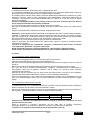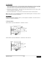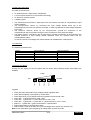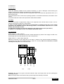
1
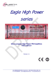
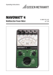
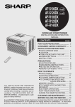
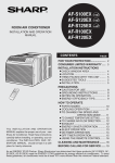
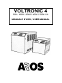
VOLTRONIC 4
500 / 1000 / 2000 / 4000 / 5000 VA
MANUALE D’USO / USER MANUAL
STABILIZZATORE ELETTRONICO
DI TENSIONE MONOFASE
“VOLTRONIC 4”
MANUALE D’USO E MANUTENZIONE
Edizione 03/03
Documento di proprietà Aros
Vietate la riproduzione e la diffusione non autorizzate
Indice
1.
•
•
•
•
•
Note generali
1.1 Dati nominali
1.2 Caratteristiche generali
1.3 Descrizione dei componenti principali
1.4 Protezioni
1.5 Segnalazioni
2.
•
•
•
•
Installazione
2.1 Scelta del luogo
2.2 Alimentazione
2.3 Allacciamenti
2.4 Norme di sicurezza
3.
•
•
•
•
Utilizzo
3.1 Avviamento e verifica funzionamento
3.2 Impostazione della tensione nominale
3.3 Ricerca Guasti
3.4 Assistenza
4. Schema elettrico
Per scopi migliorativi l’Azienda si riserva la facoltà di modificare il prodotto descritto in questo manuale in qualsiasi momento e
senza preavviso
AROS EMT1046C
1/12
ITALIANO
1. Note generali
1.1 Dati nominali
MODELLO - VA
VOLTRONIC 4 VOLTRONIC 4 VOLTRONIC 4 VOLTRONIC 4 VOLTRONIC 4
500
1000
2000
4000
5000
Tensione nominale di ingresso
220 / 230 / 240 Vac monofase
Tensione nominale di uscita
220 / 230 / 240 Vac selezionabile, monofase
Frequenza della rete
48 ÷ 62 Hz
Variazione accettata della tensione di
ingresso
Precisione di stabilizzazione
Corrente di uscita @ 230 Vac
Corrente max. di ingresso
-18% / +14% rispetto a Vout selezionata
± 3%
2,4 A
4,5 A
9A
18A
22 A
3A
6A
12 A
24A
29 A
Velocità di regolazione
2 mS x Volt
Sovraccarico
1,5 IN x 5 sec.
Fattore di potenza del carico
Qualsiasi
Distorsione armonica introdotta
<0,5%
Protezione contro i picchi di tensione
Fino a 4 kV – 130 Joule
Rendimento
98%
Raffreddamento
Naturale in aria
Temperatura di funzionamento
0°C ÷ 40°C
Umidità relativa massima
90%
Grado di protezione
IP 20
Indicazioni del display
Allarme sonoro
Ventilato
Rete OK, livello del carico, sovraccarico, allarmi
Attivato per sovraccarico, sovratensione, sovratemperatura
Protezioni in ingresso
Fusibile
Magnetotermico
Protezioni in uscita
Fusibile
Fusibile
Cavo con spina Schuko
Morsettiera interna
Collegamento in uscita
Presa Schuko
Morsettiera interna
Dimensioni LxPxH (mm)
180x215x194
230x350x275
Collegamento in ingresso
Peso (Kg)
8,2
9,5
20,5
24.5
26
Tab.1
1.2 Caratteristiche generali
Gli stabilizzatori sono progettati e costruiti secondo la Norma Tecnica EN 60950 e sono conformi ai
requisiti richiesti dalle direttive europee n° 93/68/CE riguardante la marcatura CE, n° 73/23/CE relativa
alla Bassa Tensione e n° 89/336/CE relativa alla Compatibilità Elettromagnetica.
Lo stabilizzatore è dimensionato per funzionamento a 230 Vac secondo Normativa CEI 8-6 “Tensioni
nominali dei sistemi elettrici di distribuzione pubblica a bassa tensione”.
Esso è comunque progettato per funzionare con tensione nominale 220 Vac o 240 Vac.
Lo stabilizzatore è destinato ad interporsi tra la rete di alimentazione ed i carichi, allo scopo di fornire ai
carichi una tensione di alimentazione stabilizzata. La stabilizzazione avviene sul valore medio.
Lo stabilizzatore può operare con un intervallo di variazione di carico da 0 al 100% e non è influenzato
dal fattore di potenza del carico stesso; le distorsioni armoniche introdotte sulla tensione di uscita non
sono apprezzabili. La presenza di un filtro RFI riduce l’effetto sul carico dei disturbi presenti in rete ed
analogamente quelli del carico verso la rete. Lo stabilizzatore non fornisce isolamento galvanico fra
ingresso e uscita. L’apparecchiatura è assemblata in contenitore metallico verniciato in RAL 7035
avente grado di protezione IP20.
AROS EMT1046C
2/12
ITALIANO
1.3 Descrizione dei componenti principali
I componenti principali sono:
• Un autotrasformatore monofase “multiprese”
• Un sistema di controllo a microprocessore
• Un sistema di interruttori elettronici
• Un sistema display
•
•
•
•
L’autotrasformatore monofase multiprese dispone di 7 prese di uscita da connettere all’uscita dello
stabilizzatore per poter compensare le variazioni della tensione di ingresso.
Il sistema a microprocessore, monitorando la tensione di ingresso decide quale delle prese
dell’autotrasformatore debba essere connessa all’uscita dello stabilizzatore per garantire la migliore
regolazione della tensione al carico.
Gli interruttori elettronici, comandati dal microprocessore, provvedono all’allacciamento delle prese
dell’autotrasformatore con l’uscita durante il passaggio per lo zero della tensione alternata.
Il sistema display, controllato dal microprocessore, consente di visualizzare, oltre al livello di carico,
l’eventuale presenza di tensione di ingresso fuori dai limiti di regolazione, lo stato di sovraccarico
nonché una situazione di sovratemperatura. In caso di sovraccarico, sovratensione e
sovratemperatura la segnalazione è accompagnata anche da un allarme sonoro.
1.4 Protezioni
Le protezioni dello stabilizzatore sono indicate nella tabella seguente:
Modello
Voltronic 4 - 500
Voltronic 4 - 1000
Voltronic 4 - 2000
Voltronic 4 - 4000
Voltronic 4 - 5000
Protezione in ingresso
Fusibile T4A 5x20 mm
Fusibile T6,3A 5x20 mm
Magnetotermico 16 A
Magnetotermico 25 A
Magnetotermico 32 A
Protezione in uscita
Fusibile F5A 5x20 *
Fusibile F6,3A 5x20 *
Fusibile F16A 10x38 *
Fusibile F25A 10x38 *
Fusibile F30A 10x38 *
* Sulla scheda interna
1.5 Segnalazioni
Tramite il display a diodi led posto sul pannello frontale e l’allarme acustico (buzzer) sono disponibili un
elevato numero di informazioni.
LOAD
ON
ALARM
Rosso
Giallo
Giallo
Giallo
Verde
Legenda:
•
•
•
•
•
•
•
•
•
Led verde lampeggiante lentamente: tensione d’ingresso eccedente i limiti di regolazione
Led verde lampeggiante velocemente: frequenza di ingresso eccedente i limiti
Led verde fisso : tensione d’ingresso entro i limiti di regolazione e carico <25%
Led verde + 1° led giallo: carico < 50%
Led verde + 1° e 2° led giallo: carico < 75%
Led verde + 1°, 2° e 3° led giallo: carico < 100%
Led rosso fisso + led verde e 3 led gialli: allarme per sovraccarico
Led rosso lampeggiante: allarme per sovratemperatura
Led rosso fisso e tutti gli altri spenti: allarme per sovratensione di ingresso (attivo solo
all’accensione).
Nota: Agli allarmi visivi (led rosso ) si accompagna un allarme sonoro (buzzer)
AROS EMT1046C
3/12
ITALIANO
2. Installazione
2.1 Scelta del luogo
Verificare lo stato dello stabilizzatore all’atto della consegna allo scopo di accertarne l’idoneità all’uso a
fronte di eventuali danni subiti nel trasporto.
Posizionare l’apparecchiatura in locali la cui temperatura non ecceda i limiti di specifica, su una
superficie piana e lontana da pareti e oggetti che possano ostruire le aperture di aerazione presenti sui
lati e sul fondo del contenitore.
Evitare la vicinanza con fonti di calore ed il contatto con materiali liquidi e/o infiammabili.
2.2 Alimentazione
La rete di alimentazione deve essere monofase, con tensione nominale di 220 o 230 o 240 Vac e con
una frequenza compresa tra 48 e 62 Hz.
Al fine di proteggere contro corto circuiti ed in ottemperanza alle vigenti disposizioni relative
alla sicurezza, l’apparecchiatura deve essere alimentata da interruttore con fusibili o interruttore
automatico con corrente massima di intervento adeguata alla massima corrente di entrata
(vedi Tab. 1).
E’ inoltre consigliabile l’aggiunta di un interruttore differenziale.
2.3 Allacciamenti
Modello Voltronic 4 – potenza 500 / 1000 VA
La connessione alla rete ed alle utenze avviene rispettivamente tramite cordone di alimentazione con
spina Schuko da 16 A e presa Schuko posti sul retro dell’apparecchio.
Modello Voltronic 4 - potenza 2000 / 4000 / 5000 VA
La connessione alla rete ed alle utenze avviene tramite morsetti interni, accessibili mediante la
rimozione della parete posteriore dello stabilizzatore (fissata con 4 viti). Dopo l’allacciamento
richiudere lo stabilizzatore.
I collegamenti sono qui di seguito riportati:
PE
Terre
Neutro
Fase
Neutro
Fase
Ingresso
Uscita
Importante: Assicurarsi deIla bontà del collegamento tra i conduttori di terra di ingresso e uscita ed il
morsetto giallo/verde.
Nota : Per costruzione il neutro di ingresso è collegato al neutro di uscita
AROS EMT1046C
4/12
ITALIANO
2.4 Norme di sicurezza
Lo stabilizzatore non deve funzionare senza il collegamento di terra.
E’ consigliabile l’installazione a monte dell’apparecchiatura di un interruttore differenziale secondo le
prescrizioni contenute nella Norma CEI 64-8 “Impianti elettrici utilizzatori”.
E’ possibile inserire dal lato uscita ulteriori interruttori differenziali possibilmente coordinati con quello
presente in ingresso. Alla luce delle caratteristiche dello stabilizzatore, l’interruttore differenziale da
connettere a monte dovrà avere corrente differenziale non inferiore a 30 mA allo scopo di evitare
interventi intempestivi.
All’interno dell’apparecchiatura sono presenti tensioni pericolose. Eventuali interventi devono
essere eseguiti unicamente da personale qualificato.
In caso di necessità rivolgersi ai Centri di assistenza tecnica autorizzati.
Nel caso sia necessaria la sostituzione di fusibili, essi devono essere dello stesso tipo e della stessa
portata.
Seguire scrupolosamente le indicazioni contenute nel presente manuale.
Attenzione: questa apparecchiatura è destinata esclusivamente all’uso per il quale è stata progettata e
realizzata. L’installazione deve essere eseguita seguendo le istruzioni fornite nel presente manuale.
Ogni altro impiego è da considerarsi improprio e quindi pericoloso; AROS declina ogni responsabilità
per eventuali danni a persone, animali o cose da imputarsi a quanto sopra citato.
Conservare con cura il presente manuale per ogni ulteriore consultazione.
Poiché il contenitore può essere aperto solo tramite mezzi specifici, il grado di protezione IP20 è
intrinsecamente ottenuto.
L’accesso ai componenti per installazione, ispezione e manutenzione deve essere consentito
solo al personale qualificato e preposto a tale scopo.
Prima di qualsiasi intervento, togliere alimentazione e disconnettere l’apparecchiatura.
Prima di ridare alimentazione allo stabilizzatore esso deve risultare perfettamente chiuso
3. Utilizzo
3.1 Avviamento e verifica funzionamento
Dare tensione all’apparecchiatura e chiudere l’interruttore posto sul retro.
Verificare lo stato del display a diodi led come da paragrafo 1.5.
Nel caso che il led verde lampeggi lentamente verificare che la tensione di ingresso sia entro i valori di
specifica.
Nel caso che il led verde lampeggi velocemente verificare che la frequenza di rete sia corretta.
Se il solo led rosso è acceso permanentemente, spegnere immediatamente lo stabilizzatore e
disconnetterlo dalla rete di ingresso: verificare che la stessa non ecceda il limite superiore
(sovratensione di ingresso)
Allacciare le utenze e verificare che non siano accesi tutti i led insieme: in tal caso il carico globale è
superiore alla potenza dello stabilizzatore. Ridurre il carico a valle dello stabilizzatore.
Se il led rosso lampeggia, vi è un allarme di sovratemperatura; verificare che lo stabilizzatore non sia
posto in un ambiente troppo caldo e che le feritoie di aerazione non siano ostruite da polvere o oggetti
esterni.
3.2 Impostazione della tensione nominale
Lo stabilizzatore Voltronic 4 è impostato per tensione nominale di 230 Vac durante la fase di collaudo in
fabbrica, mediante due dip-switch posti sulla scheda di controllo.
Nel caso sia necessario impostare una tensione nominale differente, (220 Vac o 240 Vac) posizionare i
due dip-switch, posti sulla scheda di controllo, secondo la seguente tabella :
DIP-SWITCH 1
DIP-SWITCH 2
220
OFF
OFF
230
ON
OFF
240
OFF
ON
Attenzione: Per effettuare tale operazione occorre accedere all’interno del contenitore ove sono
presenti tensioni pericolose.
Prima di rimuovere il coperchio, assicurarsi che sia stata tolta la tensione all’ingresso
dell’apparecchiatura. Al termine della regolazione, richiudere accuratamente il contenitore.
L’operazione va eseguita solamente da personale specializzato (vedi 2.4)
AROS EMT1046C
5/12
ITALIANO
3.3 Ricerca guasti
•
Mancanza accensione display - Assicurarsi della presenza della tensione di ingresso ai morsetti
(per lo stabilizzatore da 2 a 5 kVA) o sulla presa di rete (per gli stabilizzatori da 0,5 e 1 kVA). Per
questi ultimi verificare l’integrità del fusibile ispezionabile sul retro dello stabilizzatore.
•
Mancanza di tensione all’uscita - Assicurarsi del corretto allacciamento dei cavi di uscita e della
bontà del collegamento stabilizzatore - carico
•
Mancanza di stabilizzazione - Assicurarsi che la tensione di rete sia entro i limiti di specifica
Nota: in tutti i casi in cui non è possibile riscontrare la causa esatta del guasto o comunque in caso di
dubbio, richiedere un intervento di assistenza.
3.4 Assistenza
In caso di funzionamento irregolare, guasti o per altre esigenze, interpellare i nostri Uffici Tecnici e
richiedere un intervento di assistenza.
4. Schema elettrico
Schema elettrico di principio stabilizzatore – modelli 500 / 1000 VA
Schema elettrico di principio stabilizzatore – modelli 2000 / 4000 / 5000 VA
AROS EMT1046C
6/12
ITALIANO
ELECTRONIC VOLTAGE STABILIZER
SINGLE PHASE
“VOLTRONIC 4”
USE AND MAINTENANCE HANDBOOK
03/03 Edition
This document is Aros property
Any unauthorised reproduction or release is forbidden
Index
1.
•
•
•
•
•
GeneraI information
1.1 Technical data
1.2 General description
1.3 Main parts description
1.4 Protections
1.5 Display and alarms
2.
•
•
•
•
Installation
2.1 Site choice
2.2 Supply
2.3 Connections
2.4 Safety instructions
3.
•
•
•
•
Use
3.1 Starting-up and operating checks
3.2 Nominal voltage setting
3.3 Fault finding
3.4 Assistance
4. Electric diagram
In order to obtain better performance, the product described in the present handbook can be altered by the Company at any date
and without prior notice
AROS EMT1046C
7/12
ENGLISH
1.General informations
1.1 Technical data
MODELS - VA
VOLTRONIC 4
500
VOLTRONIC 4
1000
Nominal input voltages
VOLTRONIC 4
2000
220 / 230 / 240 Vac selectable, single phase
Main frequency
48 ÷ 62 Hz
Acceptable variation of input voltage
-18% +14% with respect to selected Vout
Regulation
Max. input current
VOLTRONIC 4
5000
220 / 230 / 240 Vac single phase
Nominal output voltages
Output current @ 230 Vac
VOLTRONIC 4
4000
± 3%
2,4 A
4,5 A
9A
18 A
22 A
3A
6A
12 A
24 A
29 A
Regulation speed
2 mS x Volt
Overload
1,5 IN x 5 sec.
Load power factor
Everyone
Introduced harmonic distortion
<0,5%
Input peak voltages protection
Up to 4 kV – 130 Joule
Efficiency
98%
Cooling
Natural
Forced
Operating temperature
0°C ÷ 40°C
Max. relative humidity
90%
Protection grade
IP 20
Display indications
Line OK, load level, overload, alarms
Acustic alarm
Active for overload, overvoltage, overtemperature
Input protections
Fuse
Automatic switch
Output protections
Fuse
Fuse
Input connections
Cable with Schuko plug
Internal terminal board
Output connections
Schuko Outlet
Internal terminal board
Dimensions WxDxH (mm)
180x215x194
230x350x275
Weight (Kg)
8,2
9,5
20,5
24,5
26
Tab.1
1.2 General description
The stabilizers are designed and built according to with the EN60950 Normative and are in compliance
with the requirements of the European Directive n°93/68/CE concerning the CE marking, n° 73/23/CE
concerning the Low Voltage Directive and n°89/336/CE concerning the Electromagnetic Campatibility.
In compliance with the IEC 60038 “Standard voltages”, the rated voltage for the stabilizer is 230 Vac.
Nevertheless, the equipment is designed to work with 220 Vac or 240 Vac nominal voltage.
The voltage stabilizer is designed to be connected between the mains and the users, in order to supply
to the loads a stabilized voltage
The stabilizing effect is reached by working on the ‘mean value’.
The equipment can operate with variable load from 0 to 100% and it is not influenced by the load
power factor; any noticeable harmonic distortion is present on the output voltage.
A RFI filter reduces the line disturbances versus the load and similarly the load disturbances versus the
main.
The stabilizer does not provide galvanic isolation between input and output.
The equipment is housed in an IP20 metallic cubicle painted with RAL 7035 varnish.
AROS EMT1046C
8/12
ENGLISH
1.3 Main parts description
The main components are:
•
•
•
•
An autotransformer, single phase, multiple taps
A control system based on microprocessor technology
An electronic switches system
A display system
•
The autotransformer provides 7 output taps to be connected to the output to compensate the input
voltage variation.
The microprocessor system, by monitoring the input voltage defines which tap of the
autotransformer has to be connected to the output, in order to guarantee the best voltage regulation
to the load.
The electronic switches, driven by the microprocessor, provide the connection of the
autotransformer taps to the output during the zero crossing time of the alternate voltage.
The display system, controlled by the microprocessor, provides informations on the load level, the
possible presence of input voltage outside regulation limits, the overload status and the
overtemperature status.
In case of overload, overvoltage and overtemperature an audible alarm is also present.
•
•
•
1.4 Protections
The stabilizer protections are :
Model
Voltronic 4 - 500
Voltronic 4 - 1000
Voltronic 4 - 2000
Voltronic 4 - 4000
Voltronic 4 - 5000
Input protection
Fuse T4A 5x20 mm
Fuse T6,3A 5x20 mm
Circuit breaker 16 A
Circuit breaker 25 A
Circuit breaker 32 A
Output protection
Fuse F5A 5x20 *
Fuse F6,3A 5x20 *
Fuse F16A 10x38 *
Fuse F25A 10x38 *
Fuse F30A 10x38 *
* on the internal board
1.5 Display and alarms
Through the led display on the front panel and the acustic alarm (buzzer) several informations are
available.
LOAD
ALARM
ON
Red
Yellow
Yellow
Yellow
Green
Legenda:
• Green led slowly intermittent: input voltage outside regulation limits
• Green led fast lighting: input frequency outside limits
• Green led fixed on: input voltage within the regulation limits and load <25%
• Green led + 1°yellow led fixed on: load < 50%
• Green led + 1°yellow led + 2° yellow led fixed on: load < 75%
• Green led + 1°yellow led + 2° yellow led +3° yellow led fixed on: load < 100%
• Red led + 3 yellow leds + green led all fixed on: overload alarm
• Red led intermittent: overtemperature alarm
• Red led fixed on and all the other off: input overvoltage alarm (active only at switch-on)
Note: to the visible alarm (red led lighting) an audible alarm (buzzer) is joined.
AROS EMT1046C
9/12
ENGLISH
2. Installation
2.1 Site choice
Check the stabilizer condition at the moment of delivery; in case of damages occurred during the
haulage, verify that the stabilizer is suitable for a normal functioning.
Install the assembly in a place where the temperature does not exceed the specification limits, on a
plane surface area.
lt is recommended not to close the air openings present on the lateral walls and on the bottom of the
cubicle.
Avoid direct heat and contact with liquid and/or inflammable materials.
2.2 Supply
The main must feed a single-phase voltage to the equipment with nominal value of 220 or 230 or
240Vac at a frequency within 48 ÷ 62 Hz range.
In order to protect against short-circuit or overload and in compliance with the in force safety
regulations, the stabilizer must be fed through either a circuit breaker with fuses or a circuit
breaker with automatic release.
The maximum activation current must depend on the highest input current (see table 1).
In addition, it is advisable to add a co-ordinated differential switch
2.3 Connections
Model Voltronic 4 - 500 / 1000 VA
The connection to the main and to the load is made respectively by mean of the supply cord with 16 A
Schuko plug and the socket Schuko on the rear of the product.
Model Voltronic 4 - 2000 / 4000 / 5000 VA
Make the connection to the mains and to the users by means of the terminal boards reachable by
removing the rear wall of the stabilizer (fixed by means of 4 screws). After the connections, reinstall
carefully the rear panel. The connections are:
PE
Grounds
Neutral
Phase
Neutral
Phase
Input
Output
Important: Be sure of the good connection between input and output wires and the yellow/green
connecting terminal.
Note: For design reason the neutral of the input and output are internally connected.
AROS EMT1046C
10/12
ENGLISH
2.4 Safety instructions
The stabilizer must not function without the earth connection.
It is recommended to put a circuit breaker with differential current release on the stabilizer input line in
compliance with the IEC 60364 “Electrical installations of buildings”.
Further circuit breakers with differential current release can be put an the output line and co-ordinated
with the one an the input line.
On the basis of the stabilizer characteristics, the circuit breaker with differential current release on the
input line should have a differential current not !ess than 30 mA in order to avoid unnecessary
activation.
Inside the equipment there are dangerous voltages.
Any maintenance operation must be carried out only by qualified personell.
If necessary, please contact an authorised ‘Technical Service Centre’.
If a fuse needs to be replaced, use new one of same type and rating.
Follow carefully the instructions given in the present handbook.
Warning: the stabilizer must be used exclusively for the purpose for which it has been designed and
built. Installation must be done accordingly to the instructions provided with the present handbook. Any
other utilisation has to be consìdered as inappropriate and therefore dangerous; AROS will not to be
held liable for possible damages to people, animals and belongings due to fall of the above.
Preserve with care this handbook for further use.
The enclosure containing the stabilizer cannot be opened without speciflc means. Therefore, both the
protection against direct contact and the campliance with the IP20 protection are inherently obtained.
Access to the components for installation, setting, inspection and maintenance must be granted
only to qualified personnel in charge of it. Before starting any operation, disconnect the
stabilizer from the main. Before to supply the stabilizer, it must be perfectly closed.
3. Use
3.1 Starting-up and operating cheks
Supply the stabilizer and close the switch on the rear.
Verify the display status as per para 1.5
In case that the green led is lighting slowly check that the input voltage value is within the limits.
If the green led is fast lighting, check that the main frequency is correct.
If the red led is permanently on, switch-off immediately the stabilizer and disconnect it from the main;
verify that the main voltage does not exceed the upper limit (Input overvoltage).
Connect the loads an verify that all the leds are not on together: in this case the load is greater than the
stabilizer power. Reduce the load.
If the red led is intermittently lighting, there is an overtemperature alarm; verify that the stabilizer is not
in a too warm ambient and that the ventilation openings are not closed by dust or external objects.
3.2 Nominal voltage setting
The AROS stabilizer is set for 230 Vac nominal voltage, during test phase in production, by means of
2 dip-switches on the control board.
In case it is necessary set a different nominal voltage (220 Vac or 240 Vac), move the dip-switches,
placed on the electronic card in accordance with the following table.
DIP-SWITCH 1
DIP-SWITCH 2
220
OFF
OFF
230
ON
OFF
240
OFF
ON
Warning: In order to make the adjustement, it is necessary to operate internally to the box where
dangerous voltages are present. Before remove the cover, be sure that the voltage at the input of the
stabilizer is not present. Made the adjustment, close carefully the box.
The operation must be carried out only by qualified personell (see 2.4)
AROS EMT1046C
11/12
ENGLISH
3.3 Fault finding
• The display does not light - Check the presence of the main voltage on the connecting terminals
(for 2 to 5 kVA models) or on the main plug (for 0,5 and 1 kVA models)
• No output voltage - Be sure of the correct connection of input and output cable and of the good quality
of connection stabilizer – load
• No stabilization - Be sure that the input voltage variation is within the limits.
Note: In case the exact fault cannot be detected or for any doubt, make request for authorized
assistance.
3.4 Assistance
In the unlikely event of malfunctions or faults, please contact our Technical Department and ask for
assistance.
4. Electrical diagram
Stabilizer electric block diagram – models 500 / 1000 VA
Stabilizer electric block diagram – models 2000 / 4000 / 5000 VA
AROS EMT1046C
12/12
ENGLISH
Via Somalia, 20
20032 CORMANO (MI) ITALY
e.mail: service@aros.it
n° verde:
Tel:
Fax:
+39 800 48 48 4
+39 02 66 32 71
+39 02 61 52 04 9