1
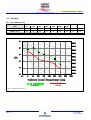
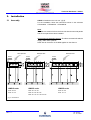
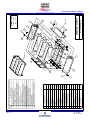
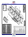
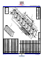
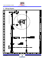
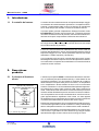
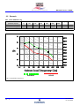
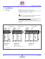
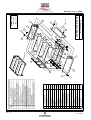
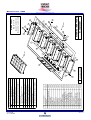
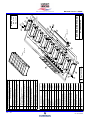
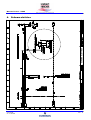
Semi ---active silencer
Silenziatore semi ---attivo
HiSAS
Technical Handbook
Manuale Tecnico
English
Italiano
cod. 271605 -- rev. 15.10.2002
Technical Handbook - HiSAS
Index
code 271605
rev. 15.10.2002
1.
Introduction
GB-1
1.1 Noise control
GB-1
2.
GB-1
Product description
2.1 Operating principle
GB-1
2.2 Technical specifications
GB-2
2.3 Technical data table
GB-2
2.4 Acoustic performance
GB-3
2.5 Example
GB-4
2.6 Advantages of the solution HiSAS
GB-5
3.
GB-6
Installation
3.1 Assembly
GB-6
3.2 Electrical connections
GB-7
3.3 Operating test
GB-7
3.4 Passive operation
GB-7
4.
GB-11
Wiring diagram
GB --- 0
Technical Handbook - HiSAS
1.
Introduction
1.1 Noise control
The noise control is getting more and more important in the field of
close control air conditioning. A very important aspect is the continuous rule evolution towards stricter and stricter limits as for sound
emission.
Within this scope, the Product development department of LiebertHIROSS has invested significant resources to find out efficient and innovative solutions for producing very silent machines without reducing the thermo-dynamical efficiency.
The product HiSAS (Semi Active Silencer) is the technologically most
advanced solution for controlling the noise in the field of close control
air conditioning.
It is well known that the traditional sound deadening systems - based
on the dissipation principle - are highly efficient for values with frequency higher than 1 kHz, while are quite limited in the range of low
and medium frequencies (100-250 Hz).
By introducing the principle of “noise active control” it is possible to
widen the frequency band also to lower values, thus realizing a system
whose response is optimized according to the incident sound pressure level.
2.
Product
description
2.1 Operating principle
protecting cover
microphone
loudspeaker
24 V
amplifier
frame
fig.1-- Operating scheme
cod. 271605
rev. 15.10.2002
The main component of HiSAS is the semi-active silencer, whose
principle scheme is reported in fig.1. The silencer has a modular structure, with each module made up of a sheet frame inside which there
are a microphone, a loudspeaker and an amplifier. This module operates as a vibration acoustic resonator where the loudspeaker diaphragm represents the mass and the air volume in the chamber represents the spring. The deadening by the resonator, sized for the max.
effect at low frequencies, remarkably increases if the sound pressure
is analyzed by a microphone and the suitably amplified signal is sent
with opposite phase to the loudspeaker, whose diaphragm is triggered
and vibrated so as to get the highest noise reduction (fig.2).
From the energy point of view, the sound energy and the power supplied to the system are changed in heat produced by the friction and
the electrical losses in the diaphragm.
From the electrical point of view a 24 V dc supply is required. Generally, the electric consumption of each single module depends on the
incident sound energy, and is included in the range 2-8 W.
GB --- 1
Technical Handbook - HiSAS
Wave width
deadening
Sound
source
Microphone
Oscillating
diaphragm
Amplifier
Energy dissipation
Wave wideness reduction
Sound deadening
fig.2-- Operating principle
2.2 Technical specifications
HiSAS is suggested by Liebert-HIROSS as optional package to be
applied to the HIMOD machines, Under version.The complete kit is
composed of:
HIMOD Under - mod. 20/24 - 27/45
!
!
No. 1 sheet duct (1000 x 890 x 350 mm).
No. 3 semi-active silencers; each silencer contains 3 modules.
!
No. 1 set of special outer panels (1 back side panel + 2 side
panels + front curtains) in sandwich material with core in high
sound insulating material.
HIMOD Under - mod. 28/34/40 - 55/65/80/85 - 26/32/42/46/55/65
!
No. 1 sheet duct (1750 x 890 x 350 mm).
!
No. 5 semi-active silencers (each silencer contains 3 modules).
!
No. 1 set of special outer panels (1 back side panel + 2 side
panels + front curtains) in sandwich material with core in high
sound insulating material.
HIMOD Under - mod. 81/99 - 12/14
!
!
No. 1 sheet duct (2500 x 890 x 350 mm).
No. 7 semi-active silencers (each silencer contains 3 modules).
!
No. 1 set of special outer panels (1 back side panel + 2 side
panels + front curtains) in sandwich material with core in high
sound insulating material.
HiSAS is installed in the suction area of the unit as indicated in fig.3.
It is important to point out that one of the most important features is its
compactness (only 350 mm high, fig.3).
2.3 Technical data table
Dimensions (mm)
1000x890x350
1750x890x350
2500x890x350
Weight (*) (kg)
120
200
270
Absorbed power (W)
19
32
45
(*) Including the special panelling.
GB --- 2
cod. 271605
rev. 15.10.2002
Technical Handbook - HiSAS
Return air
Amplifier
350 mm
HiSAS
Oscillating diaphragm
Duct
Height = 350 mm
HIMOD Under
fig.3 - Installation
2.4 Acoustic performance
The following tables show the sound deadening that can be achieved
using HiSAS in the HIMOD Under unit.
The measurements have been taken at the Liebert-HIROSS laboratory and free-field chambers of Universities and Research Institutes
specialized in the acoustic field.The sound power and pressure level is
significantly reduced around 200 Hz.
In the end, it is possible to state that by no other traditional system with
these dimensions it is possible to achieve an acoustic performance
that can be compared to the one of the HiSAS system (fig.4).
SPL (Reduction)
OCTAVE BAND FREQUENCY (Hz)
Sound pressure
level
63
125
250
500
1000
2000
4000
dB (A)
2
11
11
10
10
8
8
dB ((A))
NR
'10
'10
dB ((A))
NR
'10
-
dB ((A))
NR
'12
-
Values detected at a 2-- m distance and 1.5-- m height, machine front in free field.
PWL (Reduction - complete unit)
OCTAVE BAND FREQUENCY (Hz)
Sound power
level
63
125
250
500
1000
2000
4000
dB (A)
2
9
13
8
10
8
8
Values detected in compliance with the ISO norms.
PWL (Reduction - suction side)
OCTAVE BAND FREQUENCY (Hz)
Sound power
level
63
125
250
500
1000
2000
4000
dB (A)
2
10
14
10
10
11
10
Values detected in compliance with the ISO norms.
cod. 271605
rev. 15.10.2002
GB --- 3
Technical Handbook - HiSAS
2.5 Example
SPL (mod. HIMOD 27 UC)
Sound pressure
level
OCTAVE BAND FREQUENCY (Hz)
dB ((A))
NR
Standard dB (A)
63
58
125
61
250
54
500
51
1000
49
2000
44
4000
36
54
49
HiSAS dB (A)
56
50
43
41
39
36
28
44
39
Values detected at a 2-- m distance and 1.5-- m height, machine front in free field.
Standard
HiSAS
fig.4-- Comparison diagram
GB --- 4
cod. 271605
rev. 15.10.2002
Technical Handbook - HiSAS
2.6 Advantages of the HiSAS
solution
HiSAS has the following advantages, in comparison with the traditional silencers used for reducing the noise produced by the conditioners:
!
reduced overall dimensions,
!
high technological content,
!
!
high thermo-dynamical performance,
better acoustic performance,
!
easy installation,
!
lower cost.
The following tables show a comparison between HiSAS and a traditional silencer to get a reduction of 10 dB (A).
Overall dimensions
(height)
Air capacity reduction
cod. 271605
rev. 15.10.2002
Traditional
silencer
HiSAS
solution
2500 mm
350 mm
12 %
3%
GB --- 5
Technical Handbook - HiSAS
3.
Installation
3.1 Assembly
HiSAS is installed on the unit roof (fig.5).
For the installation, follow the instructions shown in the schemes
CG1000M12 - CG2000M12 - CG2000M46.
Note
The silencers must be fit from the front side after the two side panels
and the rear panel have been installed.
Strictly follow the assembly direction. The silencers must be fit with the
supply cable outlet upwards.
Refer also to the arrow on the label applied on the silencer.
RETURN AIR
350
250
DUCT
HiSAS
250
250
DUCT
HiSAS
350
DUCT
HiSAS
RETURN AIR
HIMOD under
HIMOD under
HIMOD under
Mod. 20 / 24
Mod. 28 / 34 / 40
Mod. 81 / 99
Mod. 27 / 45
Mod. 55 / 65 / 80 / 85
Mod. 12 / 14
350
RETURN AIR
Mod. 26 / 32 / 42 / 46 / 55 / 65
fig.5-- Installation
GB --- 6
cod. 271605
rev. 15.10.2002
Technical Handbook - HiSAS
3.2 Electrical connections
The supply for the silencers is:
Connector block
24 V dc.
The electrical cables exiting the silencers are to be connected to the
terminals in the connector block inside the electric board (fig.6, fig.7
and fig.8).
The cables exiting the silencers are identified by the numbers 1 =
positive, 2 = negative.
fig.6-- Electric board, 1000 mm front type
Connector block
Connector block
fig.7-- Electric board, 1750 mm front type
fig.8-- Electric board, 2500 mm front type
3.3 Operating check
HiSAS has been realized to ensure a high noise reduction.
If the deadening of the noise produced by the unit is not significant,
contact the Liebert-HIROSS Service that will make all the necessary checks.
If there are loud howls, one of the silencers is not operating. In this
case, de-activate HiSAS and replace the faulty element.
3.4 Passive operation
HiSAS determines a noise reduction even when it is not electrically
supplied. In this case, the acoustic performance reach lower levels.
cod. 271605
rev. 15.10.2002
GB --- 7
GB --- 8
17
16
15
14
13
12
11
10
9
8
7
6
5
4
3
2
1
Pos.
10
9
8
7
6
5
4
3
2
1
Tappo Heyman 1690 SP--625
Plug Heyman 1690 SP--625
Guarn.espansa autoad.13x8 mm
Gasket 13x8 mm
Guarn.espansa autoad.15x3 mm
Gasket 15x3 mm
Boccola per pannelli
Bush for panels
Pannello frontale
Frontal panel
Pannello laterale DX con melammina
Right lateral panel with melammina
Pannello laterale SX
Left lateral panel
Pannello schienale
Back panel
Omega supporto
Support
Supporto posteriore
Back support
Supporto frontale
Frontal support
Silenziatore attivo
Active silencer
Vite TCB M5x12 DIN7985
Screw TCB M5x12 DIN7985
Vite TE--FLANG.M6x16ST 10.9
Screw TE--FLANG.M6x16ST 10.9
Vite TCBEI M6x30 FE 10.9
Screw TCBEI M6x30 FE 10.9
Vite A/FIL. TE 4.8x13+coll ZN
Screw A/FIL. TE 4.8x13+coll ZN
Vite A/FIL. TE 6.3x16+coll ZN
Screw A/FIL. TE 6.3x16+coll ZN
Desrizione/Description
241622
236315
271304
271371
390110
390221
390600
391340
390840
275830
129235
129234
129233
129232
129230
129236
129231
Cod.
Applicare guarnizioni 17 su pannelli 1,2,3,4
Apply gasket 17 on the panels 1,2,3,4
Fissare particolare 6 sul pannello 4 con viti 9
Fix particular 6 on the panel 4 by screws 9
Fissare pannelli 2,3 con pannello 4 con viti 12+tappo 15
Fix panels 2 and 3 with panel 4 by screws 12+plugs 15
Fissare particolare 7 su pannelli 2 e 3 rispettando la
quota ”42” con viti 9
Fix particular 7 with panels 2 and 3 observing
dimension ”42” by screws 9
Fissare particolare 5 su particolari 6 e 7 con viti 10
Fix particular 5 on the particulars 6 and 7 by screws 10
Applicare guarnizioni 16 su moduli 8 (2 per lato)
Apply gaskets 16 on the moduls 8 (2 each side)
Montare plenum su unita’, fissarlo con viti 13
Set up the plenum on the unit, fixing by screws 13
Montare silenziatori attivi 8 su particolari 5
Set up active silencers 8 on the particular 5
Collegare cavi elettrici
Connect electricals cables
Chiudere il plenum con pannello 1 con viti 11+boccola 14
Close the plenum with panel 1 by screws 11 + bushes 14
OPERAZIONE/OPERATION
SEQUENZA FASI ASSEMBLAGGIO/SEQUENCE PHASE ASSEMBLY
FASE
PHASE
15
12
17
17
6
10
9
4
5
3
17
42
9
10
16
LATO CON MELAMMINA
SIDE WITH MELAMMINA
LATO CON MELAMMINA
SIDE WITH MELAMMINA
16
LATO CON MELAMMINA
SIDE WITH MELAMMINA
8
FRONT UNIT
12
7
13
11
2
11
FRONT UNIT
1
14
17
17
Nr. CG1000M12
ASSEMBLY SCHEME
14
17
ELECTRICAL CABLE
CAVO ELETTRICO
LATO CON MELAMMINA
SIDE WITH MELAMMINA
15
Mod. 27 / 45
Mod. 20 / 24
HIMOD under
Technical Handbook - HiSAS
cod. 271605
rev. 15.10.2002
cod. 271605
rev. 15.10.2002
17
16
15
14
13
12
11
10
9
8
7
6
5
4
3
2
1
Pos.
10
9
8
7
6
5
4
3
2
1
Guarn.espansa autoad.15x3 mm
Gasket 15x3 mm
Tappo Heyman 1690 SP--625
Plug Heyman 1690 SP--625
Guarn.espansa autoad.13x8 mm
Gasket 13x8 mm
Boccola per pannelli
Bush for panels
Pannello frontale
Frontal panel
Pannello laterale DX con melammina
Right lateral panel with melammina
Pannello laterale SX
Left lateral panel
Pannello schienale
Back panel
Omega supporto
Support
Supporto posteriore
Back support
Supporto frontale
Frontal support
Silenziatore attivo
Active silencer
Vite TCB M5x12 DIN7985
Screw TCB M5x12 DIN7985
Vite TE--FLANG.M6x16ST 10.9
Screw TE--FLANG.M6x16ST 10.9
Vite TCBEI M6x30 FE 10.9
Screw TCBEI M6x30 FE 10.9
Vite A/FIL. TE 4.8x13+coll ZN
Screw A/FIL. TE 4.8x13+coll ZN
Vite A/FIL. TE 6.3x16+coll ZN
Screw A/FIL. TE 6.3x16+coll ZN
Desrizione/Description
241622
236315
271304
271371
390110
390221
390600
391340
390840
275830
129633
129254
129233
129252
129230
129236
129251
Cod.
Fissare particolare 7 su pannelli 2 e 3 rispettando la
quota ”42” con viti 9
Fix particular 7 with panels 2 and 3 observing
dimension ”42” by screws 9
Fissare particolare 5 su particolari 6 e 7 con viti 10
Fix particular 5 on the particulars 6 and 7 by screws 10
Applicare guarnizioni 16 su moduli 8 (2 per lato)
Apply gaskets 16 on the moduls 8 (2 each side)
Montare plenum su unita’, fissarlo con viti 13
Set up the plenum on the unit, fixing by screws 13
Montare silenziatori attivi 8 su particolari 5
Set up active silencers 8 on the particulars 5
Collegare cavi elettrici
Connect electricals cables
Chiudere il plenum con pannello 1 con viti 11+boccole 14
Close the plenum with panel 1 by screws 11 + bushes 14
Applicare guarnizioni 17 su pannelli 1,2,3,4
Apply gasket 17 on the panels 1,2,3,4
Fissare particolare 6 sul pannello 4 con viti 9
Fix particular 6 on the panel 4 by screws 9
Fissare pannelli 2,3 con pannello 4 con viti 12+tappi 15
Fix panels 2 and 3 with panel 4 by screws 12+plugs 15
OPERAZIONE/OPERATION
(A)
SEQUENZA FASI ASSEMBLAGGIO/SEQUENCE PHASE ASSEMBLY
FASE
PHASE
10
17
6
LATO CON MELAMMINA
SIDE WITH MELAMMINA
15
12
17
4
(A)
3
17
(A)
9
FRONT UNIT
(A)
8
7
5
16
42
(A)
16
9
14
11
(A)
13
2
17
14
FRONT UNIT
17
1
CAVO ELETTRICO
ELECTRICAL CABLE
15
11
17
Nr. CG2000M17
ASSEMBLY SCHEME
(A)
12
Mod. 26 / 32 / 42 / 46 / 55 / 65
Mod. 55 / 65 / 80 / 85
Mod. 28 / 34 / 40
HIMOD under
Technical Handbook - HiSAS
GB --- 9
GB --- 10
Fissare particolare 7 su pannelli 2 e 3 rispettando la
quota ”42” con viti 9
Fix particular 7 with panels 2 and 3 observing
dimension ”42” by screws 9
Fissare particolare 5 su particolari 6 e 7 con viti 28
Fix particular 5 on the particulars 6 and 7 by screws 28
Applicare guarnizioni 16 su moduli 8 (2 per lato)
Apply gaskets 16 on the moduls 8 (2 each side)
Montare plenum su unita’, fissarlo con viti 13
Set up the plenum on the unit, fixing by screws 13
Montare silenziatori attivi 8 su particolari 5
Set up active silencers 8 on the particulars 5
Collegare cavi elettrici
Connect electricals cables
Chiudere il plenum con pannello 1 con viti 11+boccole 14
Close the plenum with panel 1 by screws 11 + bushes 14
3
4
5
6
7
8
9
10
128607
128602
275830
390840
Supporto frontale
Frontal support
Silenziatore attivo
Active silencer
Vite TCB M5x12 DIN7985
Screw TCB M5x12 DIN7985
7
8
9
390110
271371
Vite A/FIL. TE 6.3x16+coll ZN
Screw A/FIL. TE 6.3x16+coll ZN
Boccola per pannelli
Bush for panels
12
13
14
17
16
15
Guarn.espansa autoad.15x3 mm
Gasket 15x3 mm
241622
236315
271304
390221
Vite A/FIL. TE 4.8x13+coll ZN
Screw A/FIL. TE 4.8x13+coll ZN
11
Tappo Heyman 1690 SP--625
Plug Heyman 1690 SP--625
Guarn.espansa autoad.13x8 mm
Gasket 13x8 mm
390600
Vite TE--FLANG.M6x16ST 10.9
Screw TE--FLANG.M6x16ST 10.9
Vite TCBEI M6x30 FE 10.9
Screw TCBEI M6x30 FE 10.9
10
391340
129233
5
4
Supporto posteriore
Back support
3
6
12923001
Pannello laterale SX
Left lateral panel
2
12860101
12923601
Pannello laterale DX con melammina
Right lateral panel with melammina
1
Pannello schienale
Back panel
Omega supporto
Support
12860001
Pannello frontale
Frontal panel
Cod.
Fissare pannelli 2,3 con pannello 4 con viti 12+tappi 15
Fix panels 2 and 3 with panel 4 by screws 12+plugs 15
2
Desrizione/Description
Fissare particolare 6 sul pannello 4 con viti 9
Fix particular 6 on the panel 4 by screws 9
1
Pos.
Applicare guarnizioni 17 su pannelli 1,2,3,4
Apply gasket 17 on the panels 1,2,3,4
OPERAZIONE/OPERATION
SEQUENZA FASI ASSEMBLAGGIO/SEQUENCE PHASE ASSEMBLY
FASE
PHASE
(A)
10
17
6
LATO CON MELAMMINA
SIDE WITH MELAMMINA
15
12
17
4
(A)
3
17
(A)
(A)
9
5
8
7
42
16
(A)
16
FRONT UNIT
9
14
(A)
11
5
(A)
16
1
14
13
11
2
17
17
CAVO ELETTRICO
ELECTRICAL CABLE
(A)
15
Nr. CG2000M46
ASSEMBLY SCHEME
FRONT UNIT
17
(A)
12
Mod. 12 / 14
Mod. 81 / 99
HIMOD under
Technical Handbook - HiSAS
cod. 271605
rev. 15.10.2002
cod. 271605
rev. 15.10.2002
WIRING DIAGRAM
BOX ON SILENCER PLENUM
24 V dc TO TERMINAL BOARD
OF ACTIVE SILENCERS
STABILIZED FEEDER MOD. AL244
CODE HIROSS 275917
4.
2AF
STABILIZER WIRING FOR ACTIVE SILENCERS
Technical Handbook - HiSAS
Wiring diagram
GB --- 11
Manuale Tecnico - HiSAS
Indice
cod. 271605
rev. 15.10.2002
1.
Introduzione
IT-1
1.1 Il controllo del rumore
IT-1
2.
IT-1
Descrizione prodotto
2.1 Il principio di funzionamento
IT-1
2.2 Specifiche tecniche
IT-2
2.3 Tabella dati tecnici
IT-2
2.4 Prestazioni acustiche
IT-3
2.5 Esempio
IT-4
2.6 Vantaggi della soluzione HiSAS
IT-5
3.
IT-6
Installazione
3.1 Montaggio
IT-6
3.2 Collegamenti elettrici
IT-7
3.3 Verifica funzionale
IT-7
3.4 Funzionamento passivo
IT-7
4.
IT-11
Schema elettrico
IT --- 0
Manuale Tecnico - HiSAS
1.
Introduzione
1.1 Il controllo del rumore
Il controllo del rumore sta assumendo un’importanza sempre maggiore nel settore del condizionamento di precisione. Un aspetto molto importante è rappresentato dalla continua evoluzione dei regolamenti
verso limiti sempre più restrittivi in termini di emissione sonora.
In questo quadro generale il dipartimento Sviluppo Prodotto di Liebert-HIROSS ha investito notevoli risorse per individuare soluzioni
innovative ed efficienti al fine di produrre macchine estremamente silenziose senza però compromettere l’efficienza termodinamica.
Il prodotto HiSAS (Semi Active Silencer) rappresenta la soluzione
tecnologicamente più avanzata per il controllo del rumore nel campo
del condizionamento di precisione.
É noto che i sistemi tradizionali di abbattimento del rumore basati sul
principio della dissipazione, hanno una elevata efficienza per valori di
frequenze maggiori a 1 kHz, mentre presentano dei limiti nel campo
delle basse e medie frequenze (100-250 Hz).
Con l’introduzione dei concetti di “controllo attivo del rumore” è possibile allargare la banda di frequenza anche a valori più bassi e realizzare un sistema la cui risposta viene ottimizzata in funzione del livello di
pressione sonora incidente.
2.
Descrizione
prodotto
2.1 Il principio di funzionamento
copertura di protezione
microfono
autoparlante
24V
amplificatore
telaio
fig.1-- Schema di principio
cod. 271605
rev. 15.10.2002
L’elemento principale di HiSAS è costituito dal silenziatore semi-attivo il cui schema di principio è illustrato nella fig.1. Il silenziatore ha una
costruzione modulare in cui ogni modulo è composto da un telaio in
lamiera all’interno del quale sono posti un microfono, un autoparlante
ed un amplificatore. Questo modulo funziona come un risuonatore
acustico a vibrazione in cui la membrana dell’autoparlante rappresenta la massa ed il volume d’aria contenuto nella cassa costituisce la
molla. L’attenuazione del risuonatore che è dimensionato per avere il
massimo effetto alle basse frequenze aumenta in maniera considerevole se la pressione sonora viene analizzata da un microfono ed il segnale opportunamente amplificato viene inviato con fase opposta
all’autoparlante la cui membrana viene eccitata e messa in vibrazione
in maniera da massimizzare la riduzione del rumore (fig.2).
Dal punto di vista energetico si ha una trasformazione dell’energia sonora e dell’energia elettrica fornita al sistema in calore prodotto dagli
attriti e dalle perdite elettriche che si determinano nella membrana.
Dal punto di vista elettrico è richiesta l’alimentazione in corrente continua a 24 VDC. In generale il consumo elettrico di ogni singolo modulo
dipende dall’energia sonora incidente ed è nel range di 2-8 W.
IT --- 1
Manuale Tecnico - HiSAS
Attenuazione
ampiezza onda
Sorgente
sonora
Microfono
Membrana
oscillante
Dissipazione di energia
Amplificatore
Riduzione ampiezza onda
Attenuazione suono
fig.2-- Principio di base
2.2 Specifiche tecniche
HiSAS è proposto da Liebert-HIROSS come pacchetto opzionale da
applicare alle macchine HIMOD versione Under.Il kit completo è
composto da :
HIMOD Under - mod. 20/24 - 27/45
!
!
Nr. 1 condotto in lamiera (1000 x 890 x 350 mm).
Nr. 3 silenziatori semi-attivi; ogni silenziatore contiene 3 moduli.
!
Nr. 1 set di pannelli esterni speciali (1 pannello schienale + 2
pannelli laterali + tamponamenti frontali) realizzati in sandwich
con anima in materiale ad alto isolamento acustico.
HIMOD Under - mod. 28/34/40 - 55/65/80/85 - 26/32/42/46/55/65
!
Nr. 1 condotto in lamiera (1750 x 890 x 350 mm).
!
Nr. 5 silenziatori semi-attivi (ogni silenziatore contiene 3 moduli).
!
Nr. 1 set di pannelli esterni speciali (1 pannello schienale + 2
pannelli laterali + tamponamenti frontali) realizzati in sandwich
con anima in materiale ad alto isolamento acustico.
HIMOD Under - mod. 81/99 - 12/14
!
!
Nr. 1 condotto in lamiera (2500 x 890 x 350 mm).
Nr. 7 silenziatori semi-attivi; ogni silenziatore contiene 3 moduli.
!
Nr. 1 set di pannelli esterni speciali (1 pannello schienale + 2
pannelli laterali + tamponamenti frontali) realizzati in sandwich
con anima in materiale ad alto isolamento acustico.
L’HiSAS è installato nella zona di aspirazione dell’unità come indicato
in fig.3.
É importante notare come una delle caratteristiche più importanti è
rappresentata dalla sua compattezza (solo 350 mm di altezza, fig.3).
2.3 Tabella dati tecnici
Dimensioni (mm)
Pesi
(*)
(kg)
Potenza assorb. (W)
1000x890x350
1750x890x350
2500x890x350
120
200
270
19
32
45
(*) Incluso pannellatura speciale
IT --- 2
cod. 271605
rev. 15.10.2002
Manuale Tecnico - HiSAS
Aria di ritorno
Amplificatore
350 mm
HiSAS
Membrana oscillante
Condotto
Altezza = 350mm
HIMOD Under
fig.3-- Installazione
2.4 Prestazioni acustiche
Nelle tabelle seguenti sono riportati gli abbattimenti del rumore che si
possono ottenere utilizzando l’HiSAS nell’unità HIMOD Under.
Le misure sono state effettuate presso il laboratorio di Liebert HIROSS e presso camere anecoiche di Università ed Istituti di ricerca
specializzati in campo acustico. Il livello di pressione e potenza sonora
viene abbattuto in maniera significativa intorno a 200 Hz.
In conclusione possiamo affermare che con nessun altro sistema tradizionale di queste dimensioni è possibile ottenere una performance
acustica paragonabile a quella del sistema HiSAS (fig.4).
SPL (Riduzione)
FREQUENZA IN BANDA D’OTTAVA (Hz)
Livello di
pressione sonora
63
125
250
500
1000
2000
4000
dB (A)
2
11
11
10
10
8
8
dB ((A))
NR
'10
'10
dB ((A))
NR
'10
-
dB ((A))
NR
'12
-
Valori rilevati ad una distanza di 2m ed un altezza di 1,5m fronte macchina in campo libero.
PWL (Riduzione - unità completa)
FREQUENZA IN BANDA D’OTTAVA (Hz)
Livello di
Potenza Sonora
63
125
250
500
1000
2000
4000
dB (A)
2
9
13
8
10
8
8
Valori rilevati in conformità alle norme ISO.
PWL (Riduzione - lato aspirazione)
FREQUENZA IN BANDA D’OTTAVA (Hz)
Livello di
Potenza Sonora
63
125
250
500
1000
2000
4000
dB (A)
2
10
14
10
10
11
10
Valori rilevati in conformità alle norme ISO.
cod. 271605
rev. 15.10.2002
IT --- 3
Manuale Tecnico - HiSAS
2.5 Esempio
SPL (mod. HIMOD 27 UC)
FREQUENZA IN BANDA D’OTTAVA (Hz)
dB ((A))
NR
36
54
49
28
44
39
Livello di
pressione sonora
63
125
250
500
1000
2000
4000
Standard dB (A)
58
61
54
51
49
44
HiSAS dB (A)
56
50
43
41
39
36
Valori rilevati ad una distanza di 2m ed un altezza di 1,5m fronte macchina in campo libero.
Standard
HiSAS
fig.4-- Diagramma comparativo
IT --- 4
cod. 271605
rev. 15.10.2002
Manuale Tecnico - HiSAS
2.6 Vantaggi della soluzione
HiSAS
HiSAS rispetto ai silenziatori tradizionali utilizzati per la riduzione del
rumore emesso dai condizionatori, presenta i seguenti vantaggi :
! ingombri ridotti,
!
alto contenuto tecnologico,
!
!
elevate prestazioni termodinamiche,
maggiori performance acustiche,
!
facilità di installazione,
!
minor costo.
Nelle tabelle seguenti è riportato una comparazione fra HiSAS ed un
silenziatore tradizionale per ottenere una riduzione di 10 dB (A).
cod. 271605
rev. 15.10.2002
Silenziatore
tradizionale
Soluzione
HiSAS
Ingombro (altezza)
2500 mm
350 mm
Riduzione portata aria
12 %
3%
IT --- 5
Manuale Tecnico - HiSAS
3.
Installazione
3.1 Montaggio
HiSAS viene montato sul tetto del unità (fig.5).
Per l’installazione seguire le istruzioni riportate negli
CG1000M12 - CG2000M12 - CG2000M46.
schemi
N.B.
I silenziatori vanno inseriti dalla parte frontale dopo che sono stati
montati i due pannelli laterali e quello posteriore.
Fare attenzione al verso di montaggio. I silenziatori devono essere inseriti con l’uscita del cavo di alimentazione verso l’alto.
Fare riferimento anche alla freccia riportata nell’etichetta applicata al
silenziatore.
ARIA DI RITORNO
350
250
CONDOTTO
HiSAS
250
250
CONDOTTO
HiSAS
350
CONDOTTO
HiSAS
ARIA DI RITORNO
HIMOD under
HIMOD under
HIMOD under
Mod. 20 / 24
Mod. 28 / 34 / 40
Mod. 81 / 99
Mod. 27 / 45
Mod. 55 / 65 / 80 / 85
Mod. 12 / 14
350
ARIA DI RITORNO
Mod. 26 / 32 / 42 / 46 / 55 / 65
fig.5-- Installazione
IT --- 6
cod. 271605
rev. 15.10.2002
Manuale Tecnico - HiSAS
3.2 Collegamenti elettrici
L’alimentazione dei silenziatori è :
Scatola di derivazione
24 VDC.
I cavi elettrici in uscita dai silenziatori vanno collegati ai morsetti presenti nella scatola di derivazione che si trova all’interno del quadro
elettrico (fig.6, fig.7 e fig.8).
I cavi uscenti dai silenziatori sono identificati con i numeri 1 = positivo, 2 = negativo.
fig.6-- Quadro elettrico, 1000 mm tipo frontale
Scatola di derivazione
Scatola di derivazione
fig.7-- Quadro elettrico, 1750 mm tipo frontale
fig.8-- Quadro elettrico, 2500 mm
tipo frontale
3.3 Verifica funzionamento
HiSAS è stato realizzato per garantire una elevata riduzione del rumore.
Nel caso in cui l’abbattimento del rumore emesso dall’unità non fosse significativo, contattare l’assistenza Liebert-HIROSS che provvederà ad effettuare le verifiche necessarie.
Se si verificano dei sibili evidenti, significa che un silenziatore non
sta lavorando. In questo caso occorre disattivare HiSAS e sostituire
l’elemento difettoso.
3.4 Funzionamento passivo
HiSAS determina una riduzione del rumore anche quando non è
elettricamente alimentato. In questo caso le prestazioni acustiche
raggiungono livelli minori.
cod. 271605
rev. 15.10.2002
IT --- 7
IT --- 8
17
16
15
14
13
12
11
10
9
8
7
6
5
4
3
2
1
Pos.
10
9
8
7
6
5
4
3
2
1
Tappo Heyman 1690 SP--625
Plug Heyman 1690 SP--625
Guarn.espansa autoad.13x8 mm
Gasket 13x8 mm
Guarn.espansa autoad.15x3 mm
Gasket 15x3 mm
Boccola per pannelli
Bush for panels
Pannello frontale
Frontal panel
Pannello laterale DX con melammina
Right lateral panel with melammina
Pannello laterale SX
Left lateral panel
Pannello schienale
Back panel
Omega supporto
Support
Supporto posteriore
Back support
Supporto frontale
Frontal support
Silenziatore attivo
Active silencer
Vite TCB M5x12 DIN7985
Screw TCB M5x12 DIN7985
Vite TE--FLANG.M6x16ST 10.9
Screw TE--FLANG.M6x16ST 10.9
Vite TCBEI M6x30 FE 10.9
Screw TCBEI M6x30 FE 10.9
Vite A/FIL. TE 4.8x13+coll ZN
Screw A/FIL. TE 4.8x13+coll ZN
Vite A/FIL. TE 6.3x16+coll ZN
Screw A/FIL. TE 6.3x16+coll ZN
Desrizione/Description
241622
236315
271304
271371
390110
390221
390600
391340
390840
275830
129235
129234
129233
129232
129230
129236
129231
Cod.
Applicare guarnizioni 17 su pannelli 1,2,3,4
Apply gasket 17 on the panels 1,2,3,4
Fissare particolare 6 sul pannello 4 con viti 9
Fix particular 6 on the panel 4 by screws 9
Fissare pannelli 2,3 con pannello 4 con viti 12+tappo 15
Fix panels 2 and 3 with panel 4 by screws 12+plugs 15
Fissare particolare 7 su pannelli 2 e 3 rispettando la
quota ”42” con viti 9
Fix particular 7 with panels 2 and 3 observing
dimension ”42” by screws 9
Fissare particolare 5 su particolari 6 e 7 con viti 10
Fix particular 5 on the particulars 6 and 7 by screws 10
Applicare guarnizioni 16 su moduli 8 (2 per lato)
Apply gaskets 16 on the moduls 8 (2 each side)
Montare plenum su unita’, fissarlo con viti 13
Set up the plenum on the unit, fixing by screws 13
Montare silenziatori attivi 8 su particolari 5
Set up active silencers 8 on the particular 5
Collegare cavi elettrici
Connect electricals cables
Chiudere il plenum con pannello 1 con viti 11+boccola 14
Close the plenum with panel 1 by screws 11 + bushes 14
OPERAZIONE/OPERATION
SEQUENZA FASI ASSEMBLAGGIO/SEQUENCE PHASE ASSEMBLY
FASE
PHASE
15
12
17
17
6
10
9
4
5
3
17
42
9
10
16
LATO CON MELAMMINA
SIDE WITH MELAMMINA
LATO CON MELAMMINA
SIDE WITH MELAMMINA
16
LATO CON MELAMMINA
SIDE WITH MELAMMINA
8
FRONT UNIT
12
14
CAVO ELETTRICO
11
17
2
11
FRONT UNIT
1
14
17
17
Nr. CG1000M12
SCHEMA DI MONTAGGIO
7
13
LATO CON MELAMMINA
SIDE WITH MELAMMINA
15
Mod. 27 / 45
Mod. 20 / 24
HIMOD under
Manuale Tecnico - HiSAS
cod. 271605
rev. 15.10.2002
cod. 271605
rev. 15.10.2002
17
16
15
14
13
12
11
10
9
8
7
6
5
4
3
2
1
Pos.
10
9
8
7
6
5
4
3
2
1
Guarn.espansa autoad.15x3 mm
Gasket 15x3 mm
Tappo Heyman 1690 SP--625
Plug Heyman 1690 SP--625
Guarn.espansa autoad.13x8 mm
Gasket 13x8 mm
Boccola per pannelli
Bush for panels
Pannello frontale
Frontal panel
Pannello laterale DX con melammina
Right lateral panel with melammina
Pannello laterale SX
Left lateral panel
Pannello schienale
Back panel
Omega supporto
Support
Supporto posteriore
Back support
Supporto frontale
Frontal support
Silenziatore attivo
Active silencer
Vite TCB M5x12 DIN7985
Screw TCB M5x12 DIN7985
Vite TE--FLANG.M6x16ST 10.9
Screw TE--FLANG.M6x16ST 10.9
Vite TCBEI M6x30 FE 10.9
Screw TCBEI M6x30 FE 10.9
Vite A/FIL. TE 4.8x13+coll ZN
Screw A/FIL. TE 4.8x13+coll ZN
Vite A/FIL. TE 6.3x16+coll ZN
Screw A/FIL. TE 6.3x16+coll ZN
Desrizione/Description
241622
236315
271304
271371
390110
390221
390600
391340
390840
275830
129633
129254
129233
129252
129230
129236
129251
Cod.
Fissare particolare 7 su pannelli 2 e 3 rispettando la
quota ”42” con viti 9
Fix particular 7 with panels 2 and 3 observing
dimension ”42” by screws 9
Fissare particolare 5 su particolari 6 e 7 con viti 10
Fix particular 5 on the particulars 6 and 7 by screws 10
Applicare guarnizioni 16 su moduli 8 (2 per lato)
Apply gaskets 16 on the moduls 8 (2 each side)
Montare plenum su unita’, fissarlo con viti 13
Set up the plenum on the unit, fixing by screws 13
Montare silenziatori attivi 8 su particolari 5
Set up active silencers 8 on the particulars 5
Collegare cavi elettrici
Connect electricals cables
Chiudere il plenum con pannello 1 con viti 11+boccole 14
Close the plenum with panel 1 by screws 11 + bushes 14
Applicare guarnizioni 17 su pannelli 1,2,3,4
Apply gasket 17 on the panels 1,2,3,4
Fissare particolare 6 sul pannello 4 con viti 9
Fix particular 6 on the panel 4 by screws 9
Fissare pannelli 2,3 con pannello 4 con viti 12+tappi 15
Fix panels 2 and 3 with panel 4 by screws 12+plugs 15
OPERAZIONE/OPERATION
(A)
SEQUENZA FASI ASSEMBLAGGIO/SEQUENCE PHASE ASSEMBLY
FASE
PHASE
10
17
6
LATO CON MELAMMINA
SIDE WITH MELAMMINA
15
12
17
4
(A)
3
17
(A)
9
FRONT UNIT
(A)
8
7
5
16
42
(A)
16
14
11
(A)
13
2
17
17
14
FRONT UNIT
17
1
11
CAVO ELETTRICO
ELECTRICAL CABLE
15
Nr. CG2000M17
SCHEMA DI MONTAGGIO
9
(A)
12
Mod. 26 / 32 / 42 / 46 / 55 / 65
Mod. 55 / 65 / 80 / 85
Mod. 28 / 34 / 40
HIMOD under
Manuale Tecnico - HiSAS
IT --- 9
IT --- 10
Fissare particolare 7 su pannelli 2 e 3 rispettando la
quota ”42” con viti 9
Fix particular 7 with panels 2 and 3 observing
dimension ”42” by screws 9
Fissare particolare 5 su particolari 6 e 7 con viti 28
Fix particular 5 on the particulars 6 and 7 by screws 28
Applicare guarnizioni 16 su moduli 8 (2 per lato)
Apply gaskets 16 on the moduls 8 (2 each side)
Montare plenum su unita’, fissarlo con viti 13
Set up the plenum on the unit, fixing by screws 13
Montare silenziatori attivi 8 su particolari 5
Set up active silencers 8 on the particulars 5
Collegare cavi elettrici
Connect electricals cables
Chiudere il plenum con pannello 1 con viti 11+boccole 14
Close the plenum with panel 1 by screws 11 + bushes 14
4
5
6
7
8
9
10
128602
275830
390840
Supporto frontale
Frontal support
Silenziatore attivo
Active silencer
Vite TCB M5x12 DIN7985
Screw TCB M5x12 DIN7985
7
8
9
390110
271371
Vite A/FIL. TE 6.3x16+coll ZN
Screw A/FIL. TE 6.3x16+coll ZN
Boccola per pannelli
Bush for panels
12
13
14
17
16
15
Guarn.espansa autoad.15x3 mm
Gasket 15x3 mm
241622
236315
271304
390221
Vite A/FIL. TE 4.8x13+coll ZN
Screw A/FIL. TE 4.8x13+coll ZN
11
Tappo Heyman 1690 SP--625
Plug Heyman 1690 SP--625
Guarn.espansa autoad.13x8 mm
Gasket 13x8 mm
390600
Vite TE--FLANG.M6x16ST 10.9
Screw TE--FLANG.M6x16ST 10.9
Vite TCBEI M6x30 FE 10.9
Screw TCBEI M6x30 FE 10.9
10
391340
128607
6
5
4
129233
3
Supporto posteriore
Back support
12923001
Pannello laterale SX
Left lateral panel
2
12860101
12923601
Pannello laterale DX con melammina
Right lateral panel with melammina
1
Pannello schienale
Back panel
Omega supporto
Support
12860001
Pannello frontale
Frontal panel
Cod.
Fissare pannelli 2,3 con pannello 4 con viti 12+tappi 15
Fix panels 2 and 3 with panel 4 by screws 12+plugs 15
3
Desrizione/Description
Fissare particolare 6 sul pannello 4 con viti 9
Fix particular 6 on the panel 4 by screws 9
2
Pos.
Applicare guarnizioni 17 su pannelli 1,2,3,4
Apply gasket 17 on the panels 1,2,3,4
1
OPERAZIONE/OPERATION
SEQUENZA FASI ASSEMBLAGGIO/SEQUENCE PHASE ASSEMBLY
FASE
PHASE
(A)
10
17
6
LATO CON MELAMMINA
SIDE WITH MELAMMINA
15
12
17
4
(A)
3
17
(A)
(A)
9
5
8
7
42
16
(A)
16
FRONT UNIT
9
14
(A)
11
5
FRONT UNIT
17
(A)
1
14
13
11
2
17
17
CAVO ELETTRICO
ELECTRICAL CABLE
(A)
15
Nr. CG2000M46
SCHEMA DI MONTAGGIO
(A)
16
12
Mod. 12 / 14
Mod. 81 / 99
HIMOD under
Manuale Tecnico - HiSAS
cod. 271605
rev. 15.10.2002
Manuale Tecnico - HiSAS
24 VDC
cod. 271605
rev. 15.10.2002
SCHEMA ELETTRICO
Schema elettrico
2AF
4.
IT --- 11
specifications without previous notice.
98/37/CE; 89/336/CEE; 73/23/CEE; 97/23/EC
Printed in Italy by Liebert HIROSS S.p A.
Since the Liebert HIROSS Company has a policy of continuous
Οproduct
ΚατασÀευαστής
παÃόν
πÃοΪόν
είναι
improvement,δηλώνει
it reservesότι
theτο
right
to change
design
andÀατασÀευασμένο αύμφωνα με τις οδηγίες της Ε.Ε.:
Issued by T.D.Service
Il Fabbricante dichiara che questo prodotto è conforme alle direttive Europee:
The Manufacturer hereby declares that this product conforms to the European Union directives:
Der Hersteller erklärt hiermit, dass dieses Produkt den Anforderungen der Europäischen Richtlinien gerecht wird:
Le Fabricant déclare que ce produit est conforme aux directives Européennes:
El Fabricante declara que este producto es conforme a las directivas Europeas:
O Fabricante declara que este produto está em conformidade com as directivas Europeias:
Tillverkare försäkrar härmed att denna produkt överensstämmer med Europeiska Uniones direktiv:
De Fabrikant verklaart dat dit produkt conform de Europese richtlijnen is:
Vaimistaja vakuuttaa täten, että tämä tuote täyättää seuraavien EU-direktiivien vaatimukset:
Produsent erklærer herved at dette produktet er i samsvar med EU-direktiver:
Fabrikant erklærer herved, at dette produkt opfylder kravene i EU direktiverne:
Since the Liebert HIROSS Company has a policy of continuous
product improvement, it reserves the right to change design and
specifications without previous notice.
Liebert HIROSS
is a division of
EMERSON
Printed in Italy by Liebert HIROSS S.p A.
Tel. +39 049 9719111
Telefax +39 049 5841257
Internet : www.hiross.it/pde
Issued by T.D.Service
Zona Industriale Tognana
Via Leonardo da Vinci, 8
35028 Piove di Sacco (PD)
ITALY