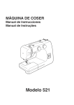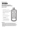
1
IMPORTANT!
DO NOT DESTROY
Swing Arm Diverter
Swing Arm Plow
Installation and
Maintenance
Manual
with Safety Information
Bulletin #627
Effective January 2011
HYTROL CONVEYOR CO., INC.
© COPYRIGHT PENDING–HYTROL CONVEYOR CO., INC.
Jonesboro, Arkansas
l Table of Contents l Índice
INTRODUCTION
Receiving and Uncrating.........................................3
INTRODUCCIÓN
Recepción y Desembalaje......................................4
INSTALLATION
Safety Precautions..................................................3
Initial Inspection......................................................5
Installation...............................................................5
Electrical Equipment...............................................7
INSTALACIÓN
Medidas de Seguridad............................................4
Inspección Inicial.....................................................6
Instalación...............................................................6
Equipo Eléctrico......................................................8
SYSTEM START-UP
Operation Safety Precautions.................................9
Swing Arm Start-Up................................................9
Maintenance Safety Precautions............................9
ARRANQUE DEL SISTEMA
Medidas de Seguridad Durante la Operación.........10
Arranque del Brazo Oscilante.................................10
Medidas de Seguridad Durante el Mantenimiento..10
OPERATION
Electrical................................................................11
Maintenance..........................................................11
Plow General Information......................................12
Wiring Diagram 120VAC Swing Arm Diverter........13
Wiring Diagram 24VDC Swing Arm Diverter.........14
Wiring Diagram 120VAC Swing Arm Plow............15
Wiring Diagram 24VDC Swing Arm Plow..............15
MODEL SWING ARM DIVERTER
Cylinder Kit...........................................................16
Plow Arm Kit.........................................................17
Plow Assembly......................................................18
OPERACIÓN
Eléctrica.................................................................11
Mantenimiento.......................................................11
Información General del Brazo..............................12
Diagrama de Cableado 120VCA-Brazo Oscilante
Desviador...............................................................13
Diagrama de Cableado 24VCD-Brazo Oscilante
Desviador...............................................................14
Diagrama de Cableado 120VCA-Brazo Oscilante.15
Diagrama de Cableado 24VCD-Brazo Oscilante...15
MODEL SWING ARM PLOW
Cylinder Kit - 30 and 45 Degree...........................19
Plow Arm Kit - 30 Degree.....................................20
Plow Arm Kit - 45 Degree.....................................21
Plow Assembly - 30 Degree.................................22
Plow Assembly - 45 Degree.................................23
MAINTENANCE
Trouble Shooting...................................................24
Preventive Maintenance........................................24
How to Order Replacement Parts.........................24
Recommended Spare Parts List...........................24
2
MODELO BRAZO OSCILANTE DESVIADOR
Kit del Cilindro........................................................16
Kit del Brazo...........................................................17
Ensamble del Brazo...............................................18
MODELO BRAZO OSCILANTE
Kit del Cilindro - 30 y 45 Grados............................19
Kit del Brazo - 30 Grados.......................................20
Kit del Brazo - 45 Grados.......................................21
Ensamble del Brazo - 30 Grados...........................22
Ensamble del Brazo - 45 Grados...........................23
MANTENIMIENTO
Resolviendo Problemas..........................................25
Mantenimiento Preventivo......................................25
Como Ordenar Partes de Repuesto.......................25
Lista de Partes de Repuesto Recomendadas........25
.
.
INTRODUCTION
This manual provides guidelines and procedures for
installing, operating, and maintaining your conveyor.
Complete assemblies are provided on pages 16 through 23
and a recommended spare parts list on page 24. Important
safety information is also provided throughout the manual.
For safety to personnel and for proper operation of your
conveyor, it is recommended that you read and follow the
instructions provided in this manual.
l Receiving and Uncrating
1. . . Check the number of items received against the bill
of lading.
2. . . Examine condition of equipment to determine if any
damage occurred during shipment.
3. . . Move all crates to area of installation.
4. . . Remove crating and check for optional equipment
that may be fastened to the conveyor. Make sure
these parts (or any foreign pieces) are removed.
NOTE: If damage has occurred or freight is missing,
Contact Hytrol conveyors or your distributor.
Inspection Notes:
INSTALLATION
l Safety Precautions
Conveyors and Related
Equipment
GUARDS AND GUARDING
Interfacing of Equipment. When two or more pieces of
equipment are interfaced, special attention shall be given
to the interfaced area to insure the presence of adequate
guarding and safety devices.
Guarding Exceptions. Wherever conditions prevail that
would require guarding under these standards, but such
guarding would render the conveyor unusable, prominent
warning means shall be provided in the area or on the
equipment in lieu of guarding.
Guarded by Location or Position. Where necessary for
the protection of employees from hazards, all exposed
moving machinery parts that present a hazard to employees
at their work station shall be mechanically or electrically
guarded, or guarded by location or position.
When a conveyor passes over a walkway, roadway, or
work station, it is considered guarded solely by location or
position if all moving parts are at least 8 ft. (2.44 m) above
the floor or walking surface or are otherwise located so that
the employee cannot inadvertently come in contact with
hazardous moving parts.
Although overhead conveyors may be guarded by location,
spill guard, pan guards, or equivalent shall be provided if
the product may fall off the conveyor for any reason and if
personnel would be endangered.
HEADROOM
When conveyors are installed above exit passageways,
aisles, or corridors, there shall be provided a minimum
clearance of 6 ft. 8 in. (2.032 m) measured vertically
from the floor or walking surface to the lowest part of the
conveyor or guards.
Where system function will be impaired by providing the
minimum clearance of 6 ft. 8 in. (2.032 m) through an
emergency exit, alternate passageways shall be provided.
It is permissible to allow passage under conveyors with less
than 6 ft. 8 in. (2.032 m) clearance from the floor for other
than emergency exits if a suitable warning indicates low
headroom.
Inspected by:
3
INTRODUCCIÓN
Este manual provee las pautas y los procedimientos para
instalar, operar y mantener su brazo oscilante. Se proporcionan
esquemas para el ensamble completo del equipo de la
página 16 a la 23 y una lista completa de partes en la página
24. También se proporciona información importante sobre
seguridad en el manual. Para seguridad del personal y para un
funcionamiento apropiado del equipo, se recomienda que se
lean y se sigan cada una de las instrucciones.
l Recepción y Desembalaje
1. . . Verifique el número de partes recibidas con respecto al
conocimiento de embarque.
2. . . Examine las condiciones del equipo con el fin de
determinar si algún daño ha ocurrido durante el
transporte.
3. . . Traslade todo el equipo al área de instalación.
4. . . Remueva todos los empagues y verifique si hay
partes opcionales que puedan estar atadas al equipo.
Asegúrese de que estas partes (u otras partes externas)
sean removidas.
NOTA: Si algún daño ha ocurrido o falta cargamento,
vea las “Notas Importantes” adheridas al embalaje.
Notas de Inspección:
INSTALACIÓN
l Medidas de Seguridad al
Instalar Transportadores y
Equipos Relacionados
GUARDAS Y PROTECCIONES
Unión del Equipo. Cuando dos o más piezas de equipo van
unidas, debe ponerse especial atención al área de unión para
asegurar que las guardas adecuadas y los dispositivos de
seguridad estén presentes.
Excepciones de Protección. Dondequiera que las guardas
sean necesarias, pero que la colocación de las mismas
inhabilite el uso del transportador, se deben proporcionar
señales de advertencia visibles en el área o en el equipo en
vez de las guardas.
Protección dada por Posición o Ubicación. Cuando sea
necesaria la protección de los empleados contra posibles
riesgos, todas las partes del equipo que estén expuestas y
en movimiento, y que puedan presentar un peligro para ellos
en sus puestos de trabajo, serán protegidas mecánica o
eléctricamente, o protegidas por su posición o ubicación.
Cuando el transportador está instalado sobre pasillos,
corredores o puestos de trabajo, se considera que está
protegido únicamente por localización o posición si todas las
partes en movimiento están mínimo a 8 pies (2.44m) de altura
del piso o área de tránsito, o si está localizado de tal manera
que el empleado no pueda entrar en contacto inadvertidamente
con dichas partes. A pesar de que los transportadores aéreos
pueden estar protegidos por su localización, guardas laterales
e inferiores deben ser proporcionadas para evitar que el
producto se caiga del transportador y así mantener al personal
fuera de peligro.
UBICACIÓN SUPERIOR
Cuando los transportadores son instalados sobre pasillos o
corredores de salida, debe dejarse un espacio libre de mínimo
6 pies 8 pulgadas (2.032m) de altura, midiendo verticalmente
desde el piso o área de tránsito hasta la parte más baja del
transportador o de las guardas. Cuando el funcionamiento
del sistema sea perjudicado al dejar el espacio libre de 6 pies
8 pulgadas (2.032m) de altura en la salida de emergencia,
pasillos alternos deben ser proporcionados. Si se proporcionan
señales de advertencia adecuadas indicando baja altura es
posible dejar espacio libre con menos de 6 pies 8 pulgadas
(2.032m) de extensión entre el piso y el transportador en los
pasillos que no sean salidas.
Verificó:
4
4
l Initial Inspection
l Installation
1. After unpacking, please inspect all hoses for loose
connections or damage that may have occurred during
shipment. Tighten any loose bolts and nuts.
1. Locate the Swing Arm sortation device per the system
layout. The mounting bracket will extend across the
bottom of the conveyor and bolt to the bottom flanges
of the conveyor channel (Note: holes may have to be
field drilled to match the holes in the mounting bracket ).
Two 3/8-inch diameter mounting bolts should be used
on each side of the conveyor to attach the bracket. The
sortation device should also be attached to the side or
top flange of the conveyor side frame through four holes
located in the device or adapter bracket; the device
should be secured with four 3/8-inch diameter bolts. Be
sure that all mounting bolts are tightened properly.
2. Check to be certain that the following components are
included: solenoid operated air valve with electrical
cord, mounting hardware package and covers with
caution labels. (Note: certain orders may include filterregulator unit with shut off valve.)
3. Once inspection has been completed, you are ready to
install the Swing Arm sortation device.
2. Adjust the arm height for a Swing Arm sortation device
to ½” above belt. To make this adjustment, loosen the
bolts in the bearing collars on the arm and move the
arm up or down as necessary. When adjustments are
complete re-tighten the bolts.
Inspection Notes:
3.
Mount the supplied filter regulator unit as close as
possible to the valve.
4.
Use 3/8” O.D. tubing to supply air from the regulator
outlet to the air valve inlet. Do not use fittings that will
reduce the air volume. It is important to supply clean,
dry air at consistent pressure to the regulator in order
to achieve good performance from your Swing Arm
sortation device.
5. Start cycling the unit at 40 PSI. After several cycles,
increase the pressure to a maximum of 80 PSI. During
test cycling, you may need to adjust the unit in order to
achieve smooth operation. Adjustment is done using
the two flow controls mounted at the valve. Begin
making adjustments by closing both the flow controls
completely, then open both flow controls in half turn
increments until the arm moves out and back in a
smooth motion. The ideal test pressure for checking this
motion is 80 PSI. Units are aligned and tested at the
factory but the flow controls are not adjusted precisely.
6. After operating the unit for several cycles, recheck all
fittings and bolted connections.
7. Adjustment of flow controls turn thumb knob counterclockwise to increase speed and clockwise to decrease
speed.
Inspected by:
In the event that damage occurs during testing, please
contact Hytrol Conveyor Company at (870) 935-3700.
5
l
Inspección Inicial
1. Al terminar de desempacar todas las abrazaderas
para determinar se alguna conexión está suelta, o
si hubo algun daño durante el transporte. Apriete los
tornillos y tuercas que estén sueltos.
2. Asegúrese de que los siguientes componentes
estén incluídos: válvula solenoide de aire con cable
eléctrico, paquete de ferretería para el montaje,
y guardas con las etiquetas de seguridad (Nota:
algunas órdenes pueden incluir una unidad filtro/
regulador con válvula de paso).
3. Una vez terminada la inspección, el brazo oscilante
para clasificación estará listo para ser instalado.
Notas de Inspeccion:
l
Instalación
1. Posicione el brazo oscilante para clasificación de acuerdo
al plano del sistema. La placa de montaje del brazo se
posiciona transversalmente en la parte inferior del canal
del transportador, y se atornilla a la parte inferior de las
pestañas del canal del transportador (Nota: puede ser
necesario taladrar huecos en el canal del transportador
durante la instalación, para que éstos encajen con los
huecos existentes de la placa de montaje). Para acoplar
la placa se deben utilizar dos tornillos de montaje de 3/8
de pulgada de diámetro a cada lado del transportador. El
equipo clasificador también debe ser acoplado al lado o a
la pestaña superior del canal lateral del transportador por
medio de cuatro huecos localizados en el clasificador, o
en el soporte de adaptación; el equipo debe ser acoplado
con cuatro tornillos de 3/8 de pulgada de diámetro.
Asegúrese de que todos los tornillos queden apretados
correctamente.
2. Ajuste la altura del brazo del equipo clasificador a 1/2 de
pulgada sobre la banda del transportador. Para lograr este
ajuste, suelte los tornillos localizados en el rodamiento del
brazo y mueva el brazo hacia arriba o hacia abajo según
sea necesario. Al terminar el ajuste, apriete los tornillos
nuevamente.
3. Instale la unidad filtro/regulador proporcionada lo más cerca
posible a la válvula.
4.
Utilice tubos con diámetro interno de 3/8 de pulgada para
el suministro de aire de la salida del regulador a la entrada
de la válvula de aire. No utilice conexiones que reduzcan
el volúmen de aire. Es muy importante que el suministro
de aire al regulador esté limpio, seco y a presión constante
para asegurar el perfecto desempeño del brazo oscilante
para clasificación.
5. Inicie el ciclo del brazo a 40 PSI. Despúes de completar
varios ciclos, aumente la presión a máximo 80 PSI. Durante
los ciclos de prueba, puede haber la necesidad de ajustar
la unidad para que su operación sea suave. Dicho ajuste
se hace utilizando los dos controles de flujo montados en
la válvula. Comience a ajustar cerrando los dos controles
completamente; luego abra los controles en incrementos
de medio giro hasta que el movimiento del brazo oscilante
sea suave. La presión ideal para probar el movimiento del
brazo es de 80 PSI. Los brazos oscilantes son alineados y
probados en la fábrica, pero los controles de flujo no son
ajustados con alta precisión.
6. Despúes de operar la unidad por varios ciclos, verifique que
todos los accesórios y conexiones estén correctamente
atornillados.
Verificó:
7. Ajuste los controles de flujo girando el botón en el sentido
de las manecillas del reloj para aumentar la velocidad y en
sentido contrario para disminuirla.
En caso de que algún daño ocurra durante la prueba del
equipo, contácte inmediatamente a Hytrol Conveyor Co. al
teléfono (870) 935-3700.
6
l Electrical Equipment
WARNING!
Electrical controls shall be installed and wired by a
qualified electrician. Wiring information for the motor and
controls are furnished by the equipment manufacturer.
CONTROLS
All such emergency stop devices shall be easily identifiable
in the immediate vicinity of such locations unless guarded
by location, position, or guards. Where the design, function,
and operation of such conveyor clearly is not hazardous to
personnel, an emergency stop device is not required.
The emergency stop device shall act directly on the control
of the conveyor concerned and shall not depend on the
stopping of any other equipment. The emergency stop
devices shall be installed so that they cannot be overridden
from other locations.
Electrical Code: All motor controls and wiring shall conform
to the National Electrical Code (Article 670 or other
applicable articles) as published by the National Fire
Protection Association and as approved by the American
National Standards Institute, Inc.
D) Inactive and unused actuators, controllers, and wiring
should be removed from control stations and panel boards,
together with obsolete diagrams, indicators, control labels,
and other material which serve to confuse the operator.
CONTROL STATIONS
SAFETY DEVICES
A) Control stations should be so arranged and located that
the operation of the equipment is visible from them, and
shall be clearly marked or labeled to indicate the function
controlled.
A) All safety devices, including wiring of electrical safety
devices, shall be arranged to operate in a “Fail-Safe”
manner, that is, if power failure or failure of the device itself
would occur, a hazardous condition must not result.
B) A conveyor which would cause injury when started shall
not be started until employees in the area are alerted by a
signal or by a designated person that the conveyor is about
to start.
When a conveyor would cause injury when started
and is automatically controlled or must be controlled from
a remote location, an audible device shall be provided
which can be clearly heard at all points along the conveyor
where personnel may be present. The warning device shall
be actuated by the controller device starting the conveyor
and shall continue for a required period of time before the
conveyor starts. A flashing light or similar visual warning
may be used in conjunction with or in place of the audible
device if more effective in particular circumstances.
Where system function would be seriously hindered or
adversely affected by the required time delay or where the
intent of the warning may be misinterpreted (i.e., a work
area with many different conveyors and allied devices),
clear, concise, and legible warning shall be provided. The
warning shall indicate that conveyors and allied equipment
may be started at any time, that danger exists, and that
personnel must keep clear. The warnings shall be provided
along the conveyor at areas not guarded by position or
location.
B) Emergency Stops and Restarts. Conveyor controls
shall be so arranged that, in case of emergency stop,
manual reset or start at the location where the emergency
stop was initiated, shall be required of the conveyor(s) and
associated equipment to resume operation.
C) Before restarting a conveyor which has been stopped
because of an emergency, an inspection of the conveyor
shall be made and the cause of the stoppage determined.
The starting device shall be locked out before any attempt
is made to remove the cause of stoppage, unless operation
is necessary to determine the cause or to safely remove the
stoppage.
Refer to ANSI Z244.1-1982, American National Standard for
Personnel Protection – Lockout/Tagout of Energy Sources
– Minimum Safety Requirements and OSHA Standard
Number 29 CFR 1910.147 “The Control of Hazardous
Energy (Lockout/Tagout).”
C) Remotely and automatically controlled conveyors, and
conveyors where operator stations are not manned or are
beyond voice and visual contact from drive areas, loading
areas, transfer points, and other potentially hazardous
locations on the conveyor path not guarded by location,
position, or guards, shall be furnished with emergency stop
buttons, pull cords, limit switches, or similar emergency stop
devices.
7
l Equipo Eléctrico
¡ADVERTENCIA!
Los controles eléctricos deben ser conectados e instalados
por un electricista calificado. La información sobre el
cableado del motor y los controles será proporcionada por el
fabricante del equipo.
CONTROLES
Código Eléctrico: Todos los controles del motor y las
conexiones deben ajustarse al “National Electrical Code“
(Artículo 670 u otros artículos aplicables) como fue publicado
por la “National Fire Protection Association” y aprobado por el
“American Standards Institute, Inc.”
ESTACIONES DE CONTROL
A) Las estaciones de control deberán estar arregladas y
ubicadas de tal forma que el funcionamiento del equipo sea
visible desde ellas y deberán estar claramente marcadas o
etiquetadas para indicar la función controlada.
B) Un transportador que pueda causar lesiones cuando es
puesto en marcha, no deberá ponerse en funcionamiento hasta
que los trabajadores en el área sean alertados por una señal
o por una persona designada que indique que el transportador
está a punto de arrancar.
Cuando un transportador puede causar lesiones al arrancar
y es controlado automáticamente, o controlado desde una
locación lejana, se debe proporcionar un dispositivo sonoro
el cual pueda ser escuchado claramente en todos los puntos
a lo largo del transportador donde el personal pueda estar
presente. El dispositivo de advertencia deberá ser activado por
el dispositivo de arranque del transportador y deberá continuar
sonando por un determinado periodo de tiempo antes de que
el transportador empiece a funcionar. Una luz intermitente o
una advertencia visual similar puede ser utilizada con o en
lugar del dispositivo sonoro si es más efectivo en circunstancias
particulares.
Cuando el funcionamiento del sistema pueda ser
seriamente obstruido o adversamente afectado por el tiempo
de retardo requerido, o cuando el intento de advertencia pueda
ser mal interpretado (ej., un área de trabajo con diversas
líneas de transportadores y con dispositivos de advertencia
relacionados), advertencias claras, concisas y legibles deberán
ser proporcionadas. Las advertencias deben indicar que los
transportadores y los equipos relacionados pueden ser puestos
en marcha en cualquier momento, que existe un peligro y que el
personal debe mantenerse alejado. Estas advertencias deben
ser proporcionadas a lo largo del transportador en áreas que no
sean protegidas por su posición o ubicación.
C) Los transportadores controlados automáticamente y desde
estaciones lejanas, y los transportadores donde las estaciones
de funcionamiento no estén controladas por una persona o
estén mas allá del alcance de la voz y del contacto visual de
las áreas de conducción, áreas de carga, puntos de transferencia y otros sitios potencialmente peligrosos localizados en
la trayectoria del transportador que no tenga protección, ya sea
dada por posición, ubicación, o guardas, deberán ser equipados
8
8
con interruptores de parada de emergencia, cordones de
parada de emergencia, interruptores de límite o dispositivos
similares para paradas de emergencia.
Todos estos dispositivos de parada de emergencia deberán
ser fácilmente identificables en las cercanías inmediatas a
estos puntos potencialmente peligrosos, a no ser que estén
protegidos dada su ubicación, posición o protegidos con
guardas. Donde el diseño, el funcionamiento, y la operación
de tales transportadores no represente un claro peligro para
el personal, no se requieren los despositivos de parada de
emergencia.
El dispositivo de parada de emergencia deberá actuar
directamente en el control del transportador concerniente y no
deberá depender de la parada de cualquier otro equipo. Los
dispositivos de parada de emergencia deberán ser instalados
de tal forma que no puedan ser anulados desde otras
localidades.
D) Los dispositivos, controles desactivados o en desuso y
las conexiones, deberán ser removidos de las estaciones de
control y de los tableros de mando, junto con los diagramas,
indicadores, etiquetas de control y otros materiales obsoletos,
los cuales se prestan para confundir al operador.
DISPOSITIVOS DE SEGURIDAD
A) Todos los dispositivos de seguridad, incluyendo la conexión
de dispositivos eléctricos, deben ser dispuestos para operar en
una manera de “autoprotección”, es decir, si se presenta una
pérdida de corriente o un fallo en el mismo dispositivo, esto no
debe resultar en una situación peligrosa.
B) Paradas de Emergencia y Reactivadores. Los controles
del transportador deberán estar dispuestos de tal manera
que en caso de una parada de emergencia, se requerirá un
activador o un arrancador manual en el lugar donde la parada
de emergencia se presenta para reanudar la operación del
transportador o transportadores y el equipo asociado.
C) Antes de reiniciar un transportador que ha sido detenido
por una emergencia, debe revisarse y determinar la causa de
la parada. El dispositivo de arranque deberá ser bloqueado
antes de intentar corregir o remover el problema a no ser que
la operación del transportador sea necesaria para determinar
la causa o para solucionar el problema de la parada sin ningún
peligro.
Refiérase a ANSI Z244.1-1982,”American National Standard
for Personnel Protection” – Lockout/Tagout of Energy Sources
– Minimum Safety Requirements and OSHA Standard Number
29 CFR 1910.147 “The Control of Hazardous Energy (Lockout/
Tagout).”
SYSTEM START-UP
l Operation Safety
Precautions
A) Only trained employees shall be permitted to operate
conveyors. Training shall include instruction in operation under
normal conditions and emergency situations.
B) Where employee safety is dependent upon stopping and/or
starting devices, they shall be kept free of obstructions to permit
ready access.
C) The area around loading and unloading points shall be kept
clear of obstructions which could endanger personnel.
l Swing Arm Start-Up
Before Swing Arm sortation device is turned on, check for
foreign objects that may have been left inside the device
during installation. These objects could cause serious
damage during start-up.
After device has been turned on and is operating, check all
moving parts to make sure they are working freely.
CAUTION!
Because of the many moving parts on the conveyor,
all personnel in the area of the conveyor need to be
warned that the conveyor is about to be started.
D) No person shall ride the load-carrying element of a conveyor
under any circumstances unless that person is specifically
authorized by the owner or employer to do so. Under those
circumstances, such employee shall only ride a conveyor which
incorporates within its supporting structure, platforms or control
stations specifically designed for carrying personnel. Under no
circumstances shall any person ride on any element of a vertical
conveyor. Owners of conveyors should affix warning devices to
the conveyor reading Do Not Ride Conveyor.
l Maintenance Safety
Precautions
E) Personnel working on or near a conveyor shall be instructed as
to the location and operation of pertinent stopping devices.
B) It is important that a maintenance program be established
to insure that all conveyor components are maintained in a
condition which does not constitute a hazard to personnel.
F) A conveyor shall be used to transport only material it is capable
of handling safely.
G) Under no circumstances shall the safety characteristics of
the conveyor be altered if such alterations would endanger
personnel.
H) Routine inspections and preventive and corrective maintenance
programs shall be conducted to insure that all safety features and
devices are retained and function properly.
I) Personnel should be alerted to the potential hazard of
entanglement in conveyors caused by items such as long hair,
loose clothing, and jewelry.
J) As a general rule, conveyors should not be cleaned while in
operation. Where proper cleaning requires the conveyor to be in
motion and a hazard exists, personnel should be made aware of
the associated hazard.
A) Maintenance, such as lubrication and adjustments, shall
be performed only by qualified and trained personnel.
C) When a conveyor is stopped for maintenance purposes,
starting devices or powered accessories shall be locked
or tagged out in accordance with a formalized procedure
designed to protect all person or groups involved with the
conveyor against an unexpected start.
D) Replace all safety devices and guards before starting
equipment for normal operation.
E) Whenever practical, DO NOT lubricate conveyors while
they are in motion. Only trained personnel who are aware
of the hazard of the conveyor in motion shall be allowed to
lubricate.
SAFETY GUARDS
Maintain all guards and safety devices IN POSITION and
IN SAFE REPAIR.
WARNING SIGNS
Maintain all warning signs in a legible condition and obey
all warnings.
9
ARRANQUE DEL SISTEMA
l Medidas de Seguridad
A) Los transportadores deben ser operados únicamente
por empleados entrenados. El entrenamiento debe incluir
instrucciones de operación bajo condiciones normales y en
situaciones de emergencia.
B) Cuando la seguridad de los trabajadores dependa de
dispositivos de parada y/o arranque, tales dispositivos deben
mantenerse libres de obstrucciones para permitir un acceso
rápido.
C) El área alrededor de los puntos de carga y descarga debe
mantenerse libre de obstrucciones, las cuales podrían poner en
peligro al personal.
D) Ninguna persona debe subirse en la parte de conducción de
carga de un transportador bajo ninguna circunstancia al menos
que esta persona sea autorizada por el dueño o por el supervisor.
Bajo estas circunstancias, el empleado debe subirse solamente en
un transportador que tenga incorporadas dentro de su estructura,
plataformas o estaciones de control especialmente diseñadas
para el traslado de personal. Bajo ninguna circunstancia, persona
alguna debe subirse en cualquier parte de un transportador
vertical. Los dueños de los transportadores deben añadir señales
de advertencia al transportador con el texto: “No subirse en el
transportador”.
E) El personal que esté trabajando en/o cerca al transportador,
debe ser instruído en cuanto a la ubicación y operación de los
dispositivos de parada.
F) Un transportador debe ser utilizado para transportar solo los
productos que sea capaz de manejar con seguridad.
G) Bajo ninguna circunstancia las características de seguridad de
un transportador deben ser alteradas si tales alteraciones puden
poner en peligro al personal.
H) Inspecciones rutinarias deben llevarse a cabo al igual que
programas de mantenimiento preventivo y correctivo, con la
finalidad de asegurar que todos los dispositivos y medidas
de seguridad sean conservados en buen estado y funcionen
correctamente.
I) El personal debe ser advertido de las posibles causas de
peligros potenciales tales como enredos en transportadores por
llevar cabello largo, ropa suelta o joyas, etc.
J) Como regla general, los transportadores no deberán limpiarse
mientras estén en funcionamiento. Cuando se requiera limpiar
el transportador estando en movimiento y exista posibilidad de
peligro, el personal deberá ser advertido de ese posible riesgo.
10
l Arranque del Brazo
Oscilante
Antes de poner en marcha el brazo oscilante desviador,
revise si hay objetos ajenos que puedan haber sido dejados
dentro del equipo durante la instalación. Estos objetos
pueden causar serios daños durante el arranque.
Después de poner en marcha el transportador y que esté
operando, revise los motores, reductores y partes en
movimiento para estar seguro de que están trabajando
libremente.
¡PRECAUCIÓN!
Debido a la cantidad de partes en movimiento del
transportador, todo el personal en el área necesita ser
advertido de que el transportador está a punto de
ponerse en marcha.
l Medidas de Seguridad en
el Mantenimiento
A) El mantenimiento, tal como lubricación y ajustes,
debe ser realizado solamente por personal calificado y
entrenado.
B) Es importante que se establezca un programa de
mantenimiento para asegurar que todos los componentes
del transportador, sean mantenidos en condiciones que no
constituyan un peligro para el personal.
C) Cuando un transportador esté parado por razones de
mantenimiento, los dispositivos de arranque o accesorios
motorizados deben ser asegurados o desconectados
siguiendo un procedimiento diseñado para evitar cualquier
arranque inesperado que pueda causar heridas a la persona
o grupos de personas involucrados con el transportador.
D) Antes de poner en marcha el equipo, vuelva a colocar
todas las guardas y dispositivos de seguridad en su lugar.
E) Siempre que sea práctico, NO lubrique los transportadores
mientras se encuentren en movimiento. Solo el personal
entrenado, que tenga conocimiento de los peligros del
transportador en movimiento, se le permitirá lubricarlos de
esta manera.
PROTECCIONES DE SEGURIDAD
Mantenga todas las guardas y dispositivos de seguridad
EN SU POSICIÓN y EN BUENAS CONDICIONES.
SEÑALES DE ADVERTENCIA
Mantenga todas las señales de advertencia en condiciones
legibles y obedézcalas.
OPERATION
OPERACIÓN
l Electrical
l Eléctrica
The Swing Arm sortation units are equipped with a single
solenoid two position air valve (120 volt AC standard or 24
volt DC optional). An electrical signal to the valve coil will
cause the unit arm to pivot across the conveyor and will
automatically return to the home position with use of the
supplied and mounted read-switch. To limit stroke distance,
loosen and slide the extend prox bracket down the length
of the cylinder.
Los brazos oscilantes para clasificación son equipados con
una válvula solenoide de aire simple y de dos posiciones (120
VCA estándar o 24 VCD como opcional). Una señal eléctrica
dada a la bobina de la válvula hace con que el brazo gire
sobre el transportador. El brazo regresará automáticamente a
su posición inicial cuando se activa el interruptor-lector que es
proporcionado e instalado en el equipo. Para limitar la distancia
de la carrera del brazo, se debe aflojar y deslizar el soporte de
proximidad de extención a lo largo del cilindro.
The Swing Arm unit is designed to rapidly push the product
off the conveyor into a chute as the product passes;
therefore the divert signal will need to be given as the
product approaches the center of the arm/chute, and
removed just prior to the cylinders bottoming out, for the
smoothest and highest cycle rates. When a spur is used
for an aftersort lane, alignment will vary with product
weights and sizes and testing will be required to make
proper transition. It is best to set up one complete divert
lane and make adjustments to be copied on others
mounted on the same conveyor.
Los brazos oscilantes son diseñados para empujar los productos
rápidamente fuera del transportador a medida que éstos van
pasando, y enviarlos a una tolva. Por lo tanto, la señal de
desviación debe ser dada en el momento en que el producto
se acerque al centro del brazo/tolva, y removida justo antes de
que los cilindros vacien el aire. Ésto garantiza una operación
suave y una tasa de ciclos por minuto bastante alta. Cuando
una espuela es instalada en el transportador para recibir
los productos clasificados, la alineación varia de acuerdo al
tamaño y al peso de los productos. Se recomienda que se
establezca una línea de desviación completa y que se hagan
los ajustes necesarios para que ésta pueda ser copiada en las
otras líneas a ser instaladas en el mismo transportador.
l Maintenance
l Mantenimiento
Your Swing Arm sortation device should require minimum
maintenance. However, we do recommend that in addition
to routine visual inspections, a thorough physical inspection
occur every three (3) months.
El brazo oscilante para clasificación requiere mantenimiento
mínimo. Sin embargo, recomendamos que además de las
inspecciones visuales rutinarias, se realicen inspecciones
físicas completas cada tres meses.
Recommended Three (3) Month Physical Inspection:
1....Verify that all bolts and nuts are tight.
2....Lubricate the rod end connectors where the bolt passes
thru with light oil.
3....Lubricate upper and lower bearings and rod end
connector with all purpose grease.
4....Check all hoses for tightness and wear.
5....Check internal bumpers for cracking or wear.
6....Check valve and cylinders for air leaks.
Inspección Fisica recomendada cada (3) tres meses:
1....Verifique que todas las tuercas y tornillos estén bien
ajustados.
2....Lubrique las varillas conectoras donde los tornillos están
incertados con aceite.
3....Lubrique los rodamientos superiores e inferiores y las
varillas conectoras con grasa de múltiple uso.
4....Revise que las abrazaderas no estén sueltas o
desgastadas.
5....Revise que los parachoques internos no estén desgastados
o agrietados.
6....Revise que la válvula y los cilindros no tengan escape de
aire.
In the event of wear, increase the frequency of service
inspections. If spare or replacement parts are required,
please refer to the SPARE PARTS LIST included in this
document.
Even though the unit is rated for 60 cycles per minute at 80
PSI, extended cycle life may be obtained by operating at
lower pressures. (Note: Cycle rates will be affected when
operating at lower pressures.)
En caso que exista desgaste, aumente la frecuencia de las
inspecciones. Si se requieren partes de repuesto, por favor
refiérase a la LISTA DE PARTES DE REPUESTO incluída en
este manual.
Apesar de que el equipo esta diseñado para trabajar a una
tasa de 60 ciclos por minuto y a 80 PSI, la vida del ciclo puede
ser extendida operando el equipo a baja presión.
(Nota: La tasa de ciclos por minuto puede ser afectada cuando
se opera a baja presión).
11
11
l
l
Plow General Information
Información General Sobre El Brazo Oscilante
FIGURE 12A
(Figura 12A)
Cylinder
OAW
(Cilindro)
Solenoid
(Solenoide)
Flow
(Flujo)
Plow Arm
(Brazo Oscilante)
Filter / Regulator
(Filtro/Regulador)
PLOW ADJUSTMENT (AJUSTE DEL BRAZO OSCILANTE)
Plow cycle time may be controlled by adjusting the main pressure regulator, flow control valve and solenoid mufflers.
NOTE: All cylinder pressure adjustments must be set after system is at operating pressure.
Use flow control valve and solenoid mufflers for fine tuning plow arm adjustments.
Note: Refer to SMC’s web site for further cylinder adjustment information.
La duración del ciclo del brazo oscilante puede ser controlada ajustando el regulador de presión principal, la válvula de control
de flujo y los silenciadores. NOTA: Todos los ajustes de la presión deben ser establecidos despúes de que el sistema
alcance la presión de operación.
Utilice la válvula de control de flujo y los silenciadores para ajustar el brazo oscilante.
Nota: Refiérase a la página de internet de SMC para información más detallada sobre los ajustes del cilindro.)
FIGURE12B
(Interruptor de Parada con Arranque Suave)
E-Stop w/Soft Start
(Figura 12B)
DIN Terminal
Mounting Bracket
(24 VCD)
24 VDC
120 VAC
(Placa de Montaje)
(120VCA)
Filter / Regulator
(Filtro/Regulador)
Drain Valve
(Válvula de Drenaje)
12
Gauge
(Indicador)
1
2
AC OR DC
Common
(CA o CD
Común)
Ground
(Tierra)
Electrical Connection (Conexión Eléctrica
para el Terminal DIN)
for DIN Terminal
(Interruptor de Parada
(Electrical E-Stop)
Eléctrico)
2
(Derivado)
BRANCH # 1
(Derivado)
BRANCH # 2
1
2
3
4
1
2
3
4
RED
(Rojo)
1
2
3
4
3
(Troncal)
TRUNK
(Troncal)
TRUNK
36"
1
2
3
4
1
1
(Gris)
GRAY
2
8"
1
2
3
4
1
2
3
4
BRANCH # 2
(Derivado)
BRANCH # 1
(Derivado)
(120
VCA)
120
VAC
4
1
1
1
1
1
ITEM QTY
5
4
3
2
1
TAG
120VAC
HOME - PROX SWITCH
(Válvula
Solenoide
SMC
094.108083)
(Solenoide de Retracción)
(Solenoide de Extención)
BLACK PIN 4 EXTEND SOLENOID
DESCRIPTION
MATERIAL
941.423003
941.400111
941.400114
941.650183
941.650182
(Válvula Solenoide de Ext)
EXTEND SOLENOID VALVE
(Interruptor de Prox)
120VAC
BROWN PIN 1 (120VCA)
COMMON
BLUE PIN 3 (Común)
WHITE PIN 2 RETRACT SOLENOID
SMC
SOLENOID
VALVE
094.108083
BLACK (4)
WHITE (2)
(Común)
COMMON
BLUE (3)
BROWN (1) (120VCA)
5
CORDSET - 3M, STRAIGHT FEMALE
VIPERSORT PUSHER Y SPLITTER(1)M12-(2)M12
SPLITTER, EURO, M-TO-2F
PROXIMITY SWITCH - 18MM,120VAC,NORM CLOSE
PROXIMITY SWITCH - 18MM,120VAC,NORM OPEN
(120
VCA)
120
VAC
6"
TYP
FIGURE 13
(Figura 13)
1
l
l
(Etiqueta)
Swing Arm Diverter (Brazo Oscilante Desviador)
Wiring Diagram 120VAC
Diagrama de Cableado 120 VCA
2
13
13
14
1
2
(Derivado)
1
2
3
4
1
2
3
4
BLUE
(Azul)
1
2
3
4
3
(Troncal)
TRUNK
(Troncal)
TRUNK
36"
1
2
3
4
1
BRANCH # 1
(Derivado)
BRANCH # 2
(Amarillo)
YELLOW
2
8"
1
2
3
4
1
2
3
4
BRANCH # 2
(Derivado)
BRANCH # 1
(Derivado)
(24
VCD)
24
VDC
1
1
1
1
1
24VDC
HOME - PROX SWITCH
(Válvula
Solenoide
SMC
094.108082)
2
DESCRIPTION
CABLE 4-PIN, 3M, STR PUSH F TO PIGTAIL
VIPERSORT PUSHER Y SPLITTER(1)M12-(2)M12
SPLITTER, EURO, M-TO-2F
PROXIMITY SWITCH - 18MM,24VDC,NORM CLOSE
PROXIMITY SWITCH - 18MM,24VDC,NORM OPEN
(Solenoide de Extención)
MATERIAL
941.423003
941.400111
941.400114
941.650181
941.650180
(Válvula Solenoide de Ext)
EXTEND SOLENOID VALVE
(Interruptor de Prox)
24VDC
BROWN PIN 1 (24VCD)
COMMON
BLUE PIN 3 (Común)
SOLENOID
WHITE PIN 2 RETRACT
(Solenoide de Retracción)
BLACK PIN 4 EXTEND SOLENOID
SMC
SOLENOID
VALVE
094.108082
BLACK (4)
WHITE (2)
(Común)
COMMON
BLUE (3)
BROWN (1) (24VDC
5
FIGURE 14
(Figura 14)
ITEM QTY
5
4
3
2
1
(24
VDC)
24
VDC
6"
TYP
l
l
1
4
TAG
(Etiqueta)
Swing Arm Diverter (Brazo Oscilante Desviador)
Wiring Diagram 24VDC
Diagrama de Cableado 24 VCD
Swing Arm Plow (Brazo Oscilante)
l
l
Wiring Diagram
Diagrama de Cableado
FIGURE 15A
(Figura 15A)
6"
TYP
TAG
(Etiqueta)
120
VAC
120 VAC
(120
VCA)
(120 VCA)
BLUE PIN 3 = AC COMMON
(CA Común)
(Azul)
BLACK PIN 4 = EXTEND SOLENOID
(Solenoide de Extención)
(Negro)
1
(Hembra)
FEMALE
SMC
SOLENOID
VALVE
094.108085
MALE
(Macho)
(Válvula
Solenoide
SMC
094.108085)
BLUE PIN 3 = AC COMMON
(CA Común)
(Azul)
BLACK PIN 4 = EXTEND SOLENOID
(Solenoide de Extención)
(Negro)
1
1
ITEM
QTY
941.423003
CORDSET - 3M, STRAIGHT FEMALE
DESCRIPTION
FIGURE 15B
(Figura 15B)
MATERIAL
6"
TYP
TAG
(Etiqueta)
24
VDC
24 VDC
(24
VCD)
(24 VCD)
BLUE PIN 3 = DC COMMON
(CD Común)
(Azul)
BLACK PIN 4 = EXTEND SOLENOID
(Solenoide de Extención)
(Negro)
1
(Hembra)
FEMALE
SMC
SOLENOID
VALVE
094.108084
MALE
(Macho)
(Válvula
Solenoide
SMC
094.108084)
BLUE PIN 3 = DC COMMON
(CD Común)
(Azul)
BLACK PIN 4 = EXTEND SOLENOID
(Solenoide de Extención)
(Negro)
1
1
ITEM
QTY
CORDSET - 3M, STRAIGHT FEMALE
DESCRIPTION
941.423003
MATERIAL
15
27
2
6
13 1/32
13
1
7
1
FIGURE 16
(Figura 16)
10
16
9
8
22 26
11
12
25
18 19 23 24
2
REF
3
10 7/8 REF
WIRING DIAGRAM
See Page 13
(Diagrama de Cableado)
(Vea la Pág 13)
13
SOLENOID
18"
24"
28"
30"
36"
15"
21"
25"
27"
33"
OAW BR
(Solenoide)
22 5/16 REF
BR
OAW
B
LH ASSEMBLY
Ensamble (Izquierda)
48 13/23"
54 13/32"
54 13/32"
54 13/32"
60 13/32"
1
2
CODE
094.108082 DG-001268
094.108083 DG-001278
ITEM #13 ITEM # 3
CHART 2
VOLTAGE
D
A
MATERIAL
PT-105379
019.230
040.303
040.402
041.103
041.204
041.902
042.1027
043.103
043.203
043.211
049.5285
092.0081
092.05011
SEE CHART 2
094.1149
094.131
094.1409
094.14093
923.0126
PT-105370
PT-105373
923.0127
940.0077
SEE CHART 2
PT-102172
WA-030482
24 VOLT DC
120 VOLT AC
2
10
5
15 14 4
21 20 17
3
B
6 1/2
7 1/4 7
DESCRIPTION
27 1 PROX FLAG - PROSORT DP
26 2 FEMALE STUD ROD END - 3/4-16 RH THREADS
25 8 3/8-16 X 1"LG HEX HEAD CAP SCREW, ZP
24 8 1/2-13 X 1-1/2"LG HEX HEAD CAP SCREW, ZP
23 8 1/2-13 NC2B HEX NUT - SEMI-FIN, REG, ZP
22 2 3/4-16 NF2B HEX JAM NUT - SEMI-FIN,REG,Z
21 2 #6-32 NC2B HEX NUT, ZP
20 2 #6-32 X 1-1/4"LG ROUND HEAD MACH SCR, ZP
19 8 1/2"ID FLAT STEEL WASHER, TYPE A, ZP
18 8 1/2"ID SPLIT LOCKWASHER, MEDIUM, ZP
17 2 .138"ID SPLIT LOCKWASHER (#6), ZP
16 8 3/8-16 SMALL FLANGE LOCKNUT, ZP
15 2 3/8"NPT 90° BRASS PIPE ELBOW
14 2 3/8"NPT X 2"LG BRASS PIPE NIPPLE
13 1 4-WAY DOUBLE SOL AIR VALVE
12 6 FT 3/8"OD POLYURETHANE TUBING - BLACK
11 2 EYE BRACKET - 1/2"OD PIN
10 6 PLASTIC ELBOW- MALE, 360 DEG SWIVEL W/RE
9 2 BRASS UNION TEE - 3/8"PLST-3/8"PLST W/RE
8 2 AIR CYLINDER - 2.5"BORE, 4"STROKE
7 1 HOME PROX BRACKET - PROSORT DP
6 1 RETURN PROX BRACKET - PROSORT DP
5 1 CONN-STRAIGHT MALE,1/2"PLST-3/8"NPT
4 2 FLOW CONTROL MUFFLER - FOR NCA1B200-1200
3 1 ELECTRICAL CONNECTION -PROSORT VIPERSORT
2 1 VALVE BRACKET - PROSORT DP
1 2 CYLINDER SUPPORT ANGLE WELD - PROSORT DP
ITEM QTY
16
Cylinder Kit
Kit del Cilindro
l
l
1
Swing Arm Diverter (Brazo Oscilante Desviador)
13 1/32
7
8
B REF
3
22 5/16 REF
OAW
BR
5 5/8
Ensamble
(Izquierda)
10
5
5 6 10
LH ASSEMBLY
4
1
5
9
6
8
6
14
14
4
14
6
1
1
1
ITEM QTY
11
10
9
8
7
6
5
4
3
2
1
11
15"
21"
23"
25"
27"
33"
60 13/32"
54 13/32"
DESCRIPTION
MATERIAL
040.607
040.610
041.106
041.800
042.2103
043.105
043.205
923.0122
PT-102175-OAW
PT-102180
928.0009
51 7/8"
C
45 7/8"
B
48 13/32"
3/4-10 X 7"LG HEX BOLT - FULL THREAD, ZP
3/4-16 X 1"LG HEX BOLT - FULL THREAD, ZP
3/4-10 NC2B HEX NUT - REGULAR, ZP
1/4-20 NC2B HEX LOCKNUT - NYLON INSERT,Z
1/4-20 X 3/4"LG FLAT HEAD BOLT, ZP
3/4"ID FLAT STEEL WASHER, ZP
3/4"ID SPLIT LOCKWASHER, ZP
PIVOT ATTACHMENT BLOCK - 3" X 8-1/2"LG
PLOW ARM - PROSORT DP
PLOW ARM CHANNEL - PROSORT DP
PIVOT SHAFT - 2-1/4"SQ X 25-1/2"LG CRS
18"
24"
26"
28"
30"
36"
OAW BR
FIGURE 17
(Figura 17)
7 1/4 7
6 1/2
30° REF
10 7/8 REF
l
l
C
2
Swing Arm Diverter (Brazo Oscilante Desviador)
Plow Arm Kit
Kit de Ensamble del Brazo
17
Swing Arm Diverter (Brazo Oscilante Desviador)
6
15
8
11
1
10
13 1/32
2
FIGURE 18
(Figura 18A)
19 22
13
4
7
5
17 23
16
21
27
9
14
B
REF
3
10 7/8 REF
27
16
22 5/16 REF
30° REF
7 1/4 7
6 1/2
15 REF
27 21 16
16
27
BR
OAW
26
25
18
29
24
16
16
21
20
28
23
28
LH ASSEMBLY
16
28
Ensamble
(Izquierda)
30
12
16
29
ITEM 15
24 VOLT DC
120 VOLT AC
TYPE
D
A
CODE
CHART 2
ITEM 14
DG-001235-D
DG-001235-A
48 13/32"
54 13/32"
54 13/32"
54 13/32"
60 13/32"
MATERIAL
010.2062
040.302
040.303
040.304
040.6015
041.106
041.907
042.300
042.301
043.101
043.200
043.201
043.205
049.310
049.5285
SEE CHART 2
SEE CHART 2
PT-084573
PT-102173
PT-102174
PT-102177
PT-102178
PT-102179-OAWL
PT-102179-OAWR
PT-102875-OAWL
PT-102875-OAWR
PT-103809-0AW
SA-045851-OAW
WA-030478
WA-030483
DG-001279-D
DG-001279-A
15"
21"
25"
27"
33"
CHART 1
OAW BR
B
18"
24"
28"
30"
36"
DESCRIPTION
30 2 BEARING - CAST IRON, 4-BOLT,2-1/4"SQ BOR
29 20 3/8-16 X 3/4"LG HEX HEAD CAP SCREW, ZP
28 21 3/8-16 X 1"LG HEX HEAD CAP SCREW, ZP
27 16 3/8-16 X 1-1/4"LG HEX HEAD CAP SCREW, ZP
26 8 3/4-10 X 2-1/2"LG HEX BOLT-FULL THREAD,Z
25 8 3/4-10 NC2B HEX NUT - REGULAR, ZP
24 6 SPEED GRIP NUT RETAINER - 3/8-16
23 8 1/4-20 X 1/2"LG TRUSS HEAD BOLT, ZP
22 4 5/16-18 X 3/4"LG TRUSS HEAD BOLT, ZP
21 12 5/16"ID (3/8"BOLT) FLAT STEEL WASHER, ZP
20 4 1/4"ID SPLIT LOCKWASHER, MEDIUM, ZP
19 4 5/16"ID SPLIT LOCKWASHER, MEDIUM, ZP
18 8 3/4"ID SPLIT LOCKWASHER, ZP
17 4 1/4-20 U-TYPE SPEED NUT (.105/.120"MATL)
16 51 3/8-16 SMALL FLANGE LOCKNUT, ZP
15 1 CYLINDER KIT
14 1 FILTER REGULATOR KIT - PROSORT DP
13 2 REINFORCEMENT BAR - 16"LG,HI-CYCLE DRIVE
12 2 SIDE GUARD - PROSORT DP
11 1 END GUARD - PROSORT DP
10 1 BASE SUPPORT CHANNEL - PROSORT DP
9 1 TOP ATTACHMENT ANGLE - PROSORT DP
8
1 BASE SUPPORT ANGLE -LH,24"OAW,PROSORT DP
7
1 BASE SUPPORT ANGLE -RH,24"OAW,PROSORT DP
6
1 STIFFENER ANGLE -LH
5
1 STIFFENER ANGLE -RH
4
1 BOTTOM GUARD PLATE
3
1 PLOW ARM KIT
2 2 SPACER CHANNEL WELD - PROSORT DP
1 1 SHAFT SUPPORT WELD - PROSORT DP
ITEM QTY
18
Plow Assembly
Ensamble del Brazo
l
l
1
21 20 17
15 14 4
5
10
7
13
3
11
25
2
(Solenoide)
SOLENOID
13
(Diagrama de Cableado - Vea la Pág 15)
7 1/4 7
6 1/2
BR
OAW
DG-001249-D 24 VOLT DC
DG-001249-A 120 VOLT AC
TYPE
CHART 1
PART
NUMBER
Ensamble (Izquierda)
LH ASSEMBLY
24 VOLT DC 094.108084
120 VOLT AC 094.108085
ITEM #13
CHART 2
VOLTAGE
3
4
CODE
923.01282
923.0128
ITEM #7
CHART 3
30 DEG
45 DEG
DIM B
RETURN PROX BRACKET - PROSORT DP
CONN-STRAIGHT MALE,1/2"PLST-3/8"NPT
FLOW CONTROL MUFFLER - FOR NCA1B200-1200
PROX FLAG - PROSORT DP
VALVE BRACKET - PROSORT DP
CYLINDER SUPPORT ANGLE WELD - PROSORT DP
DESCRIPTION
ITEM QTY
FEMALE STUD ROD END - 3/4-16 RH THREADS
AIR CYLINDER - 2.5"BORE,
3/8"OD POLYURETHANE TUBING - BLACK
EYE BRACKET - 1/2"OD PIN
PLASTIC ELBOW- MALE, 360 DEG SWIVEL W/RE
BRASS UNION TEE - 3/8"PLST-3/8"PLST W/RE
1/2-13 X 1-1/2"LG HEX HEAD CAP SCREW, ZP
1/2-13 NC2B HEX NUT - SEMI-FIN, REG, ZP
3/4-16 NF2B HEX JAM NUT - SEMI-FIN,REG,Z
#6-32 NC2B HEX NUT, ZP
#6-32 X 1-1/4"LG ROUND HEAD MACH SCR, ZP
1/2"ID FLAT STEEL WASHER, TYPE A, ZP
1/2"ID SPLIT LOCKWASHER, MEDIUM, ZP
.138"ID SPLIT LOCKWASHER (#6), ZP
3/8-16 SMALL FLANGE LOCKNUT, ZP
3/8"NPT 90° BRASS PIPE ELBOW
3/8"NPT X 2"LG BRASS PIPE NIPPLE
4-WAY SINGLE SOL AIR VALVE
26 1
25 8
24 8
23 8
22 2
21 2
20 2
19 8
18 8
17 2
16 8
15 2
14 2
13 1
12 6 FT
11 2
10 6
9 2
8 2
7 2
6 1
5 1
4 2
3 1
2 1
1 2
MATERIAL
040.402
041.103
041.204
041.902
042.1027
043.103
043.203
043.211
049.5285
092.0081
092.05011
SEE CHART 2
094.1149
094.131
094.1409
094.14093
019.230
SEE CHART 3
PT-105373
923.0127
940.0077
PT-105379
PT-102172
WA-030482
CORDSET - 3M, STRAIGHT FEMALE
941.423003
3/8-16 X 1"LG HEX HEAD CAP SCREW, ZP 040.303
30 DEGREE
45 DEGREE
DEG OF DIVERT
FIGURE 19
(Figura 19)
WIRING DIAGRAM (See Page 15)
18 19 23 24
12
16
9
8
22 26
l
l
6
Swing Arm Plow 30 & 45 Degree
(Brazo Oscilante de 30 y 45 Grados)
Cylinder Kit
Kit del Cilindro
19
Swing Arm Plow 30 Degree
(Brazo Oscilante de 30 Grados)
l Plow Arm Kit
l Kit de Ensamble del Brazo
FIGURE 20
(Figura 20)
7
A REF
8
B
2
4
6 1/2
7 1/4 7
10 7/8
REF
30° REF
OAW
BR
4
6 1/2
2
5
9
11
15"
21"
25"
27"
33"
53 1/4"
59 1/4"
65 1/4"
71 1/4"
83 1/4"
B
50"
56"
62"
68"
80"
ITEM 2
PT-103138-18
PT-103138-24
PT-103138-28
PT-103138-30
PT-103138-36
DESCRIPTION
MATERIAL
4 3/4-10 X 7"LG HEX BOLT - FULL THREAD, ZP 040.607
4 3/4-16 X 1"LG HEX BOLT - FULL THREAD, ZP 040.610
4 3/4-10 NC2B HEX NUT - REGULAR, ZP
041.106
9 5/16-18 NC2B HEX LOCKNUT -NYLON INSERT,Z 041.799
9 5/16-18 X 1"LG TRUSS HEAD BOLT, ZP
042.305
2 3/4"ID FLAT STEEL WASHER, ZP
043.105
8 3/4"ID SPLIT LOCKWASHER, ZP
043.205
099.4605
4.17 WEARSTRIP - 3-1/4" DOGBONE
4 PIVOT ATTACHMENT BLOCK - 3" X 8-1/2"LG 923.0122
1 PIVOT ARM
SEE CHART
1 PIVOT SHAFT - 2-1/4"SQ X 20-1/4"LG CRS 928.0008
18"
24"
28"
30"
36"
OAW BR A
LH ASSEMBLY
(Ensamble - Izquierda)
5 6 10
10
5
3
1
11
10
9
8
7
6
5
4
3
2
1
ITEM QTY
20
A REF
8
4
7 1/4 7
6 1/2
45°
BR
OAW
LH ASSEMBLY
6 1/2
4
2
10
5
5 6 10
(Ensamble - Izquierda)
3
1
5
9
11
10
9
8
7
6
5
4
3
2
1
4
4
4
9
9
2
8
4.17
4
1
1
ITEM QTY
11
15"
21"
27"
33"
41 1/4"
47 1/4"
53 1/4"
65 1/4"
35"
44"
50"
59"
ITEM 2
DESCRIPTION
MATERIAL
040.607
040.610
041.106
041.799
042.305
043.105
043.205
099.4605
923.0122
SEE CHART
928.0008
PT-106332-18
PT-106332-24
PT-106332-30
PT-106332-36
3/4-10 X 7"LG HEX BOLT - FULL THREAD, ZP
3/4-16 X 1"LG HEX BOLT - FULL THREAD, ZP
3/4-10 NC2B HEX NUT - REGULAR, ZP
5/16-18 NC2B HEX LOCKNUT -NYLON INSERT,Z
5/16-18 X 1"LG TRUSS HEAD BOLT, ZP
3/4"ID FLAT STEEL WASHER, ZP
3/4"ID SPLIT LOCKWASHER, ZP
WEARSTRIP - 3-1/4" DOGBONE
PIVOT ATTACHMENT BLOCK - 3" X 8-1/2"LG
PIVOT ARM
PIVOT SHAFT - 2-1/4"SQ X 20-1/4"LG CRS
18"
24"
30"
36"
OAW BR A B
FIGURE 21
(Figura 21)
7
B
2
10 7/8 REF
(Brazo Oscilante de 45 Grados)
l Plow Arm Kit
l Kit de Ensamble del Brazo
Swing Arm Plow 45 Degree
21
Swing Arm Plow 30 Degree
(Brazo Oscilante de 30 Grados)
6
14
8
11
1
10
13 1/32
2
FIGURE 22
(Figura 22)
19 22
7
5
17 23
4
13
16
21
27
15
9
A
3
27 21 16
6 1/2
7 1/4
13 13/16 REF
10 7/8 REF
27
16
30° REF
7
16
29
20 16
29
26
25
18
23
6 1/2
29
24
30
LH ASSEMBLY
(Ensamble - Izquierda)
BR
OAW
16
21
28
12
16
28
16
29
VOLTAGE
24 VOLT DC
120 VOLT AC
CODE
ITEM #14
ITEM #15
A
DG-001279-D
DG-001279-A
BR
50
56
62
68
80
DG-001249-3D *
DG-001249-3A *
OAW
15"
21"
25"
27"
33"
D
A
18"
24"
28"
30"
36"
DESCRIPTION
MATERIAL
30 2 BEARING - CAST IRON, 4-BOLT,2-1/4"SQ BOR
010.2062
29 20 3/8-16 X 3/4"LG HEX HEAD CAP SCREW, ZP
040.302
28 21 3/8-16 X 1"LG HEX HEAD CAP SCREW, ZP
040.303
27 16 3/8-16 X 1-1/4"LG HEX HEAD CAP SCREW, ZP
040.304
26 8 3/4-10 X 2-1/2"LG HEX BOLT-FULL THREAD,Z
040.6015
25 8 3/4-10 NC2B HEX NUT - REGULAR, ZP
041.106
24 6 SPEED GRIP NUT RETAINER - 3/8-16
041.907
23 8 1/4-20 X 1/2"LG TRUSS HEAD BOLT, ZP
042.300
22 4 5/16-18 X 3/4"LG TRUSS HEAD BOLT, ZP
042.301
21 12 5/16"ID (3/8"BOLT) FLAT STEEL WASHER, ZP
043.101
20 4 1/4"ID SPLIT LOCKWASHER, MEDIUM, ZP
043.200
19 4 5/16"ID SPLIT LOCKWASHER, MEDIUM, ZP
043.201
18 8 3/4"ID SPLIT LOCKWASHER, ZP
043.205
17 4 1/4-20 U-TYPE SPEED NUT (.105/.120"MATL)
049.310
16 51 3/8-16 SMALL FLANGE LOCKNUT, ZP
049.5285
15 1 FILTER REGULATOR KIT - PROSORT DP
SEE CHART
14 1 CYLINDER KIT
SEE CHART
13 2 REINFORCEMENT BAR - 16"LG,HI-CYCLE DRIVE PT-084573
12 2 SIDE GUARD - PROSORT DP
PT-102173
11 1 END GUARD - PROSORT DP
PT-102174
10 1 BASE SUPPORT CHANNEL - PROSORT DP
PT-102177
9 1 TOP ATTACHMENT ANGLE - PROSORT DP
PT-102178
8 1 BASE SUPPORT ANGLE -LH,24"OAW,PROSORT 60 PT-102179-OAWL
7 1 BASE SUPPORT ANGLE -RH,24"OAW,PROSORT 60 PT-102179-OAWR
6 1 STIFFENER ANGLE -LH
PT-102875-OAWL
5 1 STIFFENER ANGLE -RH
PT-102875-OAWR
4 1 BOTTOM GUARD PLATE
PT-103809-OAW
3 1 PLOW ARM KIT
SA-046012-OAW
2 2 SPACER CHANNEL WELD - PROSORT DP
WA-030478
1 1 SHAFT SUPPORT WELD - PROSORT DP
WA-030483
ITEM QTY
22
Plow Assembly
Ensamble del Brazo
l
l
6
8
14
10
2
13 1/32
5
16
21
27
15
9
A
REF
3
27 21 16
45°
7 1/4
6 1/2
10 7/8 REF
7
27
16
16
29
13 13/16 REF
BR
20 16
29
26
25
18
23
6 1/2
16
21
28
OAW
29
24
30
12
LH ASSEMBLY
(Ensamble - Izquierda)
16
28
16
29
15"
21"
27"
33"
DESCRIPTION
MATERIAL
010.2062
040.302
040.303
040.304
040.6015
041.106
041.907
042.300
042.301
043.101
043.200
043.201
043.205
049.310
049.5285
SEE CHART
SEE CHART
PT-084573
PT-102173
PT-102174
PT-102177
PT-102178
PT-102179-OAWL
PT-102179-OAWR
PT-102875-OAWL
PT-102875-OAWR
PT-103809-OAW
SA-047486-OAW
WA-030478
WA-030483
A
38"
44"
50"
62"
BR
18"
24"
30"
36"
30 2 BEARING - CAST IRON, 4-BOLT,2-1/4"SQ BOR
29 20 3/8-16 X 3/4"LG HEX HEAD CAP SCREW, ZP
28 21 3/8-16 X 1"LG HEX HEAD CAP SCREW, ZP
27 16 3/8-16 X 1-1/4"LG HEX HEAD CAP SCREW, ZP
26 8 3/4-10 X 2-1/2"LG HEX BOLT-FULL THREAD,Z
25 8 3/4-10 NC2B HEX NUT - REGULAR, ZP
24 6 SPEED GRIP NUT RETAINER - 3/8-16
23 8 1/4-20 X 1/2"LG TRUSS HEAD BOLT, ZP
22 4 5/16-18 X 3/4"LG TRUSS HEAD BOLT, ZP
21 12 5/16"ID (3/8"BOLT) FLAT STEEL WASHER, ZP
20 4 1/4"ID SPLIT LOCKWASHER, MEDIUM, ZP
19 4 5/16"ID SPLIT LOCKWASHER, MEDIUM, ZP
18 8 3/4"ID SPLIT LOCKWASHER, ZP
17 4 1/4-20 U-TYPE SPEED NUT (.105/.120"MATL)
16 51 3/8-16 SMALL FLANGE LOCKNUT, ZP
15 1 FILTER REGULATOR KIT - PROSORT DP
14 1 CYLINDER KIT
13 2 REINFORCEMENT BAR - 16"LG,HI-CYCLE DRIVE
12 2 SIDE GUARD - PROSORT DP
11 1 END GUARD - PROSORT DP
10 1 BASE SUPPORT CHANNEL - PROSORT DP
9 1 TOP ATTACHMENT ANGLE - PROSORT DP
8 1 BASE SUPPORT ANGLE -LH,24"OAW,PROSORT 60
7 1 BASE SUPPORT ANGLE -RH,24"OAW,PROSORT 60
6 1 STIFFENER ANGLE -LH
5 1 STIFFENER ANGLE -RH
4 1 BOTTOM GUARD PLATE
3 1 PLOW ARM KIT
2 2 SPACER CHANNEL WELD - PROSORT DP
1 1 SHAFT SUPPORT WELD - PROSORT DP
ITEM QTY
ITEM #15
DG-001279-D
DG-001279-A
OAW
ITEM #14
DG-001249-4D
DG-001249-4A
D
A
VOLTAGE CODE
24 VOLT DC
120 VOLT AC
FIGURE 23
(Figura 23)
13
4
7
17 23
19 22
l
l
1
11
Swing Arm Plow 45 Degree
(Brazo Oscilante de 45 Grados)
Plow Assembly
Ensamble del Brazo
23
MAINTENANCE
l Trouble Shooting
TROUBLE
CAUSE
SOLUTION
Plow will not activate.
1) No power to plow
2) Air loss to plow
1) Check power source.
2) Check air supply.
Little or no cushion on retract stroke.
1) Cushion regulator pressure too low
2) Cushion “bleed-off” needs adjustment
1) Adjust cushion regulator.
2) Adjust cushion “bleed-off”.
1) Cushion regulator pressure too high
2) Cushion “bleed-off” needs adjustment
1) Adjust cushion regulator.
2) Adjust cushion “bleed-off”.
1) Main regulator pressure too high
1) Adjust main regulator.
Arm “bounces” at end of retract stroke or Arm
partially extended.
Arm hits hard or travels slow in both
directions.
l Preventive Maintenance
DAILY
1. . . Check air pressure at regulators*
2. . . Check for water in filter* bowl. Drain when water level
reaches the lower baffle.
3. . . Check for excessive noise or vibration during
operation.
WEEKLY
1. . . Remove cover and check for loose fasteners.
2. . . Check cylinder rod for dirt build-up. Clean as needed
with a clean, dry cloth.
NOTE: For SMC cylinder Maintenance information go to SMC’s E_TEC website.
*NOTE: See Packing Envelope for information from supplier on How to Service the FRL(Filter/Regulator/Lubricator)
NOTE: Check Set Screws after the first 24 Hours of operation.
l
How To Order Replacement Parts
Included in this manual are parts drawings with complete replacement parts lists. When ordering replacement parts:
1. . . Identify the Conveyor factory order number.
2. . . Identify the part number and description from the Spare Parts List below.
3. . . Contact your Hytrol distributor from whom the sortation device was purchased and order the necessary parts.
4. . . If you are in a work stoppage situation, please make this known immediately.
Swing Arm Diverter/Plow
Recommended Spare Parts List
Número de Parte
094.108082
094.108083
094.108084
094.108085
923.0126
923.0128
923.01282
019.230
24
24
Descripción
Solenoid Valve 24v - Model Swing Arm Diverter
Solenoid Valve 120v - Model Swing Arm Diverter
Solenoid Valve 24v - Model Swing Arm Plow
Solenoid Valve 120v - Model Swing Arm Plow
Air Cylinder - Model Swing Arm Diverter
Air Cylinder - Model Swing Arm Plow 45 Degree
Air Cylinder - Model Swing Arm Plow 30 Degree
5/8-18 Female Rod End Connector
MANTENIMIENTO
l
Resolviendo Problemas
PROBLEMA
CAUSA
SOLUCIÓN
1) El brazo no recibe poder.
2) Pérdida de aire al brazo.
1) La presión del regulador de amortiguación está
Poco o nada de amortiguación en la carrera
demasiado baja.
de retracción.
2) La descarga de amortiguación necesita ajuste.
Brazo “rebota” al final de la carrera de 1) La presión del regulador de amortiguación está
demasiado alta.
retracción o permanece parcialmente
2) La descarga de amortiguación necesita ajuste.
extendido.
1) Revise la fuente de poder.
2) Revise la fuente de aire.
El brazo golpea fuerte o gira lentamente en 1) La presión del regulador principal está
demasiado alta.
ambas direcciones.
1) Ajuste el regulador principal.
El brazo no se activa.
l
1) Ajuste el regulador de amortiguación.
2) Ajuste la descarga de amortiguación.
1) Ajuste el regulador de amortiguación.
2) Ajuste la descarga de amortiguación.
Mantenimiento Preventivo
DIARIAMENTE
1. . . Revise la presión del aire de los reguladores*
2. . . Revise el nivel de água en el recipiente del filtro*.
Drene el vaso cuando el nivel de água alcance el nivel
más bajo del baffle.
3. . . Revise si existe ruído o vibración excesiva durante
la operación.
SEMANALMENTE
1. . . Remueva la guarda y revise si hay algún tornillo
suelto.
2. . . Revise se la varilla del cilindro está sucia. Limpie si
es necesario con un trapo limpio y seco.
NOTA: Para información sobre el Mantenimiento de los cilindros SMC, por favor remítase a la página de internet de E-TEC.
*NOTA: Para las instrucciones de Como Mantener el FRL (Filtro/Regulador/Lubricador) Proporcionadas por el proveedor,
refiérase al Sobre de Empaque adjunto.
NOTA: Revise todos los tornillos despúes de las primeras 24 horas de operación.
l
Como Ordenar Partes de Repuesto
Dibujos de las partes y listas completas de las partes de repuesto están incluidos en este manual. Cuando ordene
partes de repuesto, por favor refiérse al siguinte procedimiento:
1.
2.
3.
4.
.
.
.
.
.Identifíque el número de órden del Transportador emitido por la fábrica.
.Identifíque la descripción y el número de parte que aparece en la Lista de Partes abajo.
.Contácte al Distribuidor que le vendió el equipo originalmente y ordene las partes necesárias.
.Infome si se encuentra en una situación critica para prestarle el servicio lo más rápido posible.
Lista de partes de repuesto recomendadas para el
Brazo Oscilante Desviador
Número de Parte
094.108082
094.108083
094.108084
094.108085
923.0126
923.0128
923.01282
019.230
Descripción
Válvula Solenoide de 24V - Modelo Brazo Oscilante Desviador
Válvula Solenoide de 120V - Modelo Brazo Oscilante Desviador
Válvula Solenoide de 24V - Modelo Brazo Oscilante
Válvula Solenoide de 120V - Modelo Brazo Oscilante
Cilindro de Aire - Modelo Brazo Oscilante Desviador
Cilindro de Aire - Modelo Brazo Oscilante de 45 Grados
Cilindro de Aire - Modelo Brazo Oscilante de 30 Grados
Varilla Conectora Hembra de 5/8-18
25
25
Notes (Notas)
26
Notes (Notas)
27
www.hytrol.com
HYTROL CONVEYOR COMPANY, INC.
2020 Hytrol Street
Jonesboro, Arkansas 72401
U.S.A.
Phone: (870) 935-3700
EFFECTIVE JANUARY 2011