1
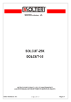
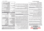
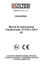
PANEL FRONTAL / FRONT PANEL
MANUAL DE INSTRUCCIONES
INSTRUCCIONES PARA EL USO Y EL MANTENIMIENTO, LEA ESTE
MANUAL ANTES DE PONER EN MARCHA EL EQUIPO
INSTRUCTION MANUAL
INSTRUCTIONS FOR THE USE AND MAINTENANCE, READ THIS
MANUAL BEFORE STARTING THE EQUIPMENT
MI03031-03 07/2012
INDICE
INDICE..............................................................................................................1
INTRODUCCIÓN ..............................................................................................2
PANEL DE MANDOS........................................................................................2
AJUSTES E INDICADORES ............................................................................3
POSIBLES ANOMALÍAS Y DEFECTOS ..........................................................4
DECLARACIÓN DE CONFORMIDAD..............................................................A1
CERTIFICADO DE GARANTÍA ........................................................................A1
SOLTER SOLDADURA S.L.
1
INTRODUCCIÓN
Agradecemos su deferencia hacia nuestra marca y esperamos le sea de gran utilidad el equipo de
soldadura que acaba de adquirir.
El presente manual de instrucciones contiene las advertencias necesarias para una correcta utilización dentro de las máximas condiciones de seguridad para el operario.
Los equipos de soldadura SOLTER deben ser empleados por personal experto que conozca y comprenda los riesgos involucrados en la utilización de los mismos.
En caso de incomprensión o duda sobre este manual les rogamos que se ponga en contacto con nosotros.
La manipulación del equipo de soldadura conlleva un peligro importante de lesión. Rogamos se abstenga de efectuar cualquier manipulación en el mismo. Sólo personal técnicamente preparado puede
realizarlo.
SOLTER Soldadura, S.L. declina toda responsbilidad por practicas negligentes en la utilización y/o
manipulación. En este manual debe adjuntarse y conservarse con el equipo adquirido.
Es responsabilidad de las personas que los utilicen y reparen que el producto no deje de cumplir los
requisitos de las normas mencionadas.
PANEL DE MANDOS
Partes del panel de mandos
1-Interruptor ON/OFF
2-Selector diámetro de hilo
3-Selector modo de soldadura
4-Enhebrado de hilo manual
5-Regulación velocidad de hilo/Offset
6-Indicador modo manual activado
7-Indicador modo sinérgico activado
8-Regulación tiempo spot
9-Selección modo sinérgico/manual
10-Indicadores de anomalías
11-Selector de material
Figura 1
Selector modo de soldadura
Selecciona entre los diferentes modos de trabajo, a cada pulsación cambia al modo siguiente.
Posibles modos:
2T
4T
2T con SPOT (soldadura de puntos)
Selección modo sinérgico/manual
Con el pulsador 9 (Figura 1) podemos elegir entre el modo manual, indicador verde iluminado, y el
modo sinérgico, en este caso se iluminarán los indicadores de material y diámetro usando las teclas 2
y 11 (Figura 1).
Enhebrado de hilo manual
Usando la tecla 4 (Figura 1) podemos realizar el enhebrado manual del alambre, la velocidad del enhebrado la controlaremos con el regulador nº5 (Figura1).
SOLTER SOLDADURA S.L.
2
Ajuste SPOT
Si tenemos activado el modo SPOT podremos ajustar el tiempo del punto de soladura entre 0,1segundos y 5 segundos (Regulador 8 figura 1).Debemos mantener el pulsador de la antorcha accionado y
el equipo parará la alimentación del hilo y la poténcia automáticamente al final del tiempo.
AJUSTES E INDICADORES
Indicadores del panel frontal (10 figura 1)
-Indicador A:
Indicador de anomalía. Indica una anomalía interna del equipo, puede iluminarse esporádicamente
durante el funcionamiento del equipo sin afectar al funcionamiento de este. En caso de permanecer
iluminado avisar al servició técnico.
-Indicador B:
Indica el sobrecalentamiento del equipo. Dejar enfriar el equipo durante unos minutos.
-Indicador C:
Indicador de anomalía en el refrigerador (depende del equipo). Indica un mal funcionamiento del refrigerador, debido a la falta de líquido refrigerante en el circuito o por que este está obstruido.
En el caso de iniciar el cebado de la bomba puede iluminarse, en este caso parar el refrigerador con
el interruptor situado en la potencia y volver a ponerlo en marcha. Puede que tenga que repetir la
operación varias veces, hasta conseguir el cebado de la bomba.
-Indicador D:
Indica que el equipo está suministrando potencia, debe lucir siempre que tengamos el pulsador de la
antorcha apretado.
Modo manual
El equipo permite ajustar la velocidad del motor desde el mínimo unos 2m/min (depende del modelo)
al máximo (depende del modelo). En este modo se deberá ajustar la velocidad con el ajuste 5 (figura
1), para adecuarla a la potencia que tengamos seleccionada.
Modo sinérgico
Este modo de trabajo proporciona un ajuste automático de la velocidad del alimentador dependiendo
del material y la potencia ajustada. En este caso el ajuste (5 Figura 1) varía la velocidad en un +/10%, para hacer pequeños ajustes en el arco. En la posición +10% tendremos un arco muy corto y en
la posición -10% tendremos un arco con tendencia a globular. Se recomienda siempre ajustarlo a laposición 0%.
Ajuste del modo sinérgico
Dos posibilidades de selección, el primer selector nos permite ajustar el diámetro del alambre que utilizamos, el segundo nos permite escoger el material. Para una óptima operación del modo sinérgico
se debe elegir correctamente el material y el diámetro del alambre.
Si seleccionamos el modo manual se apagaran todos los indicadores, recuperando su estado inicial al
volver a activar el modo sinérgico.
Los pilotos indicadores de material pueden encenderse en intermitencia, esto nos indica que estamos
fuera de la capacidad de ajuste para la potencia seleccionada.
SOLTER SOLDADURA S.L.
3
Ajuste Burn-back
Ajusta la longitud del alambre que quedará al finalizar la soldadura. Para
materiales tipo acero o acero inoxidable ajustar un tiempo largo. En materiales blandos como el aluminio debe ajustarse un tiempo corto.
Ajuste arranque (Slope up)
Con este ajuste determinamos la suavidad de la arrancada. En modo manual ajustará la rampa de aceleración del alambre y debe ajustarse correctamente para cada material y potencia.
En modo sinérgico ajusta la velocidad inicial del alambre, se deberá ajustar dependiendo del diámetro
de este. El arranque del arco va controlado por el contacto de este con la pieza, no se iniciará la aceleración del alambre si no hay un contacto con la pieza a soldar.
Tanto el ajuste de Burn Back como el de Slope up están situados en la parte interna del panel frontal,
accediendo a ellos desde el alojamiento de el alambre de soldadura.
POSIBLES ANOMALÍAS Y SOLUCIONES
Anomalía
En modo sinérgico. El arco es
muy alto.
En modo sinérgico. El arco es
muy corto y impacta sobre la
pieza.
El alambre da bandazos y parece no tener una velocidad
estable
El indicador de material parpadea
SOLTER SOLDADURA S.L.
Causa
Poca velocidad de alambre
Mucha velocidad de alambre
El consumible de la antorcha
no es el adecuado o está desgastado.
La guía del alambre de la antorcha no es la adecuada o
está en mal estado
La tensión del arrastre no es
la correcta
Tenemos seleccionada una
potencia superior a la capacidad de suministro de alambre
del equipo
Solución
Verificar que tenemos seleccionado el material i el diámetro adecuados
Verificar que tenemos seleccionado el material i el diámetro adecuados
Cambiar el consumible
Verificar la guía y sustituirla si
procede
Verificar y ajustar la tensión
Reducir la potencia del
equipo.
Cambiar a un alambre de diámetro superior
4
INDEX
INDEX ..............................................................................................................5
INTRODUCTION ..............................................................................................6
CONTROL PANEL ............................................................................................6
ADJUSTMENTS AND LED INDICATORS ........................................................7
TROUBLESHOOTING......................................................................................8
DECLARATION OF CONFORMITY ................................................................A1
WARRANTY CERTIFICATE ............................................................................A1
SOLTER SOLDADURA S.L.
5
INTRODUCTION
Thank you for selecting one of our products. We are sure you will find this unit very useful. .
These instructions contain the necessary information and security warnings to enable the correct use
of the unit under the safest conditions for the operator.
In order to obtain the maximum performance of this unit, we suggest you read the instructions carefully.
If in any doubt regarding any aspect of the instructions, please contact us for guidance. Operation of
this equipment involves serious risk of electric shock. Do not touch the live parts or the internal parts
of the unit. Only qualified personnel are authorised to do so.
SOLTER SOLDADURA, S.L. will in no way be held liable for any damage caused by the improper use
or operation of this unit. These instructions are provided together with the unit you have purchased
and must be kept for future reference.
It is the sole responsibility of the user or of the personnel who repair this unit to guarantee that it keeps
complying with all the relevant local or state safety requirements.
CONTROL PANEL
Parts
1-ON/OFF Switch
2-Wire Diameter Selector
3-Welding Mode Selector
4-Manual Wire Threading
5-Wire-feed Speed Control / Offset
6-Manual Welding Mode Indicator active
7-Synergic Welding Mode Indicator Active
8-Time Adaptive Spot- Welding Control
9-Synergic / Manual Mode Selection
10-Anomalies Indicators
11-Material Selection
Figure 1
Welding Mode Selector Switch
This switch enables choosing between different working modes. Press the selector to switch from one
mode to another.
Welding Modes allowed:
2T
4T
2T SPOT mode (spot-welding)
Synergic / Manual Mode Selection
Switch number 9 (Fig. 1) enables choosing between Manual Mode – the green LED illuminates – and
Synergic Mode. When switched to this latter mode wire diameter and base material LEDs illuminate
(keys 2 and 11, fig. 1).
Manual Wire Threading
Switch number 4 (fig. 1) enables threading the wire manually. Wire-feed speed can be adjusted
through knob number 5 (Fig.1)
SOLTER SOLDADURA S.L.
6
SPOT-welding Adjustment
When the unit is set on SPOT-welding mode, spot-welding time can be adjusted between 0.1 and 5
seconds (knob 8, fig. 1). Press and hold the torch trigger and it will stop automatically after the pre-selected time.
ADJUSTMENTS AND LED INDICATORS
Front Panel Indicators (10 figure 1)
LED A:
It lights to indicate that the unit suffers an internal anomaly. It may illuminate now and then while the
unit is running without affecting the results. If the LED remains lit, contact your technical service.
-LED B:
It lights to indicate overheating. If this LED illuminates you must let the unit cool down for some minutes.
-LED C:
It lights to indicate there is a malfunction in the cooling system (depending on the equipment). This
could be caused by a lack of refrigerant in the circuit or because the circuit is blocked. It may also illuminate when you proceed to prime the pump. In this case stop the cooling-system by turning off the
power switch and then turn it on again. You may need to repeat this operation several times before the
pump is primed.
- LED D:
It lights to indicate that the equipment is supplying power. It must always be lit if you are pressing the
torch trigger
Manual Mode
This mode allows setting the welding speed manually from a minimum of 2m/ min to the maximum
(this range depends on the model). If you select this mode, set the speed using knob 5 (fig. 1) in order
to adjust it to the pre-selected voltage.
Synergic Mode
This mode offers the automatic adjustment of the wire-feed speed according to material used and pre-
selected voltage. In this mode the automatic speed value (5, fig. 1) can be adjusted within the range of
+/- 10% in order to make small adjustments to the arc. The + 10% position gives a very short arc whereas the -10% position gives an arc that tends to be globular. The optimum value is position 0%.
Synergic Mode Setting
This mode has two knobs. The first knob enables to adjust the diameter of the wire being used; the second allows selecting the base material. In order to maximise the operating efficiency of the unit material used and wire’s diameter selectors must be properly adjusted when working in this mode.
If you select the manual mode, all LED lights will turn off. The unit will go back to its initial state when
you activate the synergic mode again.
If the “material used” LED is flashing this indicates you have exceeded the parameters that are suitable to work with the pre-selected voltage.
SOLTER SOLDADURA S.L.
7
Burn-back Time Adjustment
This function allows setting a time delay between the arc stopping and the wire-feeding. Materials
such as steel or stainless steel require a long burn-back time whereas soft materials such as Aluminium need a short burn-back time.
Slope-Up Adjustment
It allows you to determine how smooth you want the welding to start. When working in manual mode
you must properly adjust acceleration time depending on material used and voltage.
In the Synergic Mode the initial wire speed is set according to the wire’s diameter. The arc’s start is
controlled by the contact of the arc with the work piece. Acceleration will only take place if there is contact with the work piece.
Both the Burn-back and the Slope-Up adjustments are located inside the front panel. You may access
them through the welding wire compartment.
POSSIBLE PROBLEMS AND SOLUTIONS
Problem
Welding in Synergic Mode the
arc length is too long
Welding in Synergic Mode the
arc length is too short and impacts on the work piece
Wire feeds erratically at an
unsteady speed
Possible Cause
Low wire feeding speed
Excessive wire feeding speed
Incorrect or worn out contact
tip
Incorrect or worn out torch
wire guide
Incorrect tension on drive rolls
The selected voltage exceeds
The “material” indicator LED is
the unit’s wire-feeding capaflashing
city.
SOLTER SOLDADURA S.L.
Solution
Check you have set correctly
the “material used” and “wire
diameter” parameters
Check that you have set correctly the “material used” and
“wire diameter” parameters
Replace contact tip
Check wire guide and replace
if necessary
Check and adjust drive tension
Check for the correct voltage.
Change to larger diameter
wire
8
SOLTER SOLDADURA S.L.
A9