1
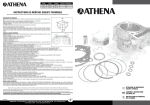
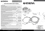
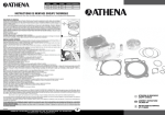
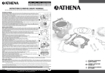
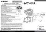
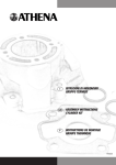
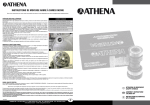
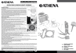
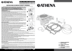
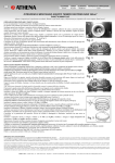
ALESAGE
COURSE
CYLINDREE
RAPPORT DE COMPRESSION
63 mm
48,8 mm
152,1 cc
10:1
INSTRUCTIONS DE MONTAGE GROUPE THERMIQUE
Nous vous remercions pour avoir choisi nos produits et restons à votre disposition pour tous renseignements supplémentaires.
PRELIMINAIRES ET DEMONTAGE:
Laver soigneusement le véhicule et le moteur. Démonter dans l’ordre: Siège, carènes, réservoir, silencieux d’échappement, collecteur
d’échappement, plaques de fixation du groupe thermique, le tube d’évent du cache-culbuteur, la bougie ainsi que le carburateur.
Ôter le cache-culbuteur et le bouchon du trou de regard, puis aligner, en tournant l’arbre dans le sens inverse des aiguilles d’une
montre, la marque située sur le volant avec le repère du carter d’allumage “Δ” (fig.3, réf. A). Détendre le tendeur de chaîne et s’assurer que le piston soit au point mort haut (PMH). Contrôler que la ligne de repère se trouvant sur la roue dentée de la distribution
soit alignée avec la marque “Δ” de la culasse “Δ” (fig. 2). Ôter le tendeur de chaîne et la roue dentée de distribution depuis l’arbre à
cames en veillant à ne pas faire tomber les boulons et les rondelles. Desserrer avec un schéma en croix les boulons de la culasse et
déposer (pour éviter de déformer la culasse, desserrer chaque écrou d’1/4 de tour à la fois). Retirer le joint et les goujons de centrage, démonter le cylindre et couvrir l’ouverture du carter moteur afin d’éviter qu’aucune impureté n’entre. Ôter la garniture de base et
le piston.
Vérifier les pièces suivantes: bielle: contrôler qu’elle soit en bon état pour être utilisée; culasse: nettoyer les éventuels encrassements au fond de la culasse; soupapes d’aspiration-échappement: vérifier l’étanchéité et le jeu, en se conformant au manuel d’utilisation
et entretien du véhicule.
La fiabilité de votre moteur est également garantie par les bonnes conditions de ces pièces.
1
MONTAGE DU GROUPE THERMIQUE:
Nettoyer soigneusement les pièces originales qui seront réutilisées, ainsi que toutes les nouvelles pièces du groupe thermique Athena,
en prêtant une attention particulière à ce qu’il n’y ait pas d’impuretés à l’intérieur des divers canaux du cylindre ou dans le piston.
Installer les segments en évitant d’endommager le piston et en s’assurant que la marque du segment haut soit dirigée vers le haut.
Positionner les segments comme indiqué sur la fig. 1.
Couvrir l’ouverture du carter avec du papier. Installer le piston, en positionnant la marque de la « flèche » en direction de l’échappement.
Après avoir lubrifié l’axe, l’introduire dans le piston, en le faisant avancer avec la pression de la main; après avoir introduit les bagues
de blocage de l’axe, s’assurer scrupuleusement que ces dernières soient disposées dans leur logement.
Positionner la nouvelle garniture de base du cylindre fournie dans le kit Athena et les goupilles de centrage sur le carter.
Graisser le corps du cylindre, le piston et les segments avec de l’huile pour moteur propre, puis installer le cylindre en comprimant
les segments.
N.B. Ne pas forcer outre mesure le cylindre, car cela pourrait causer la rupture des segments.
Installer le guide chaîne de la distribution, en alignant ses languettes avec les rainures du cylindre.
2
Installer les goupilles de centrage, ainsi que le nouveau joint de culasse fourni dans le kit Athena.
Installer la culasse de cylindre avec les rondelles correspondantes, puis serrer les écrous, en suivant un schéma croisé en deux ou
trois phases, selon le couple indiqué: 22 N•m (2,2 kgf•m).
Serrer les boulons M6 de montage de la culasse, selon le couple indiqué: 9,8 N•m (1,0 kgf•m).
Contrôler que l’arbre à cames puisse bouger sans aucun problème.
Installer la roue dentée de la distribution sur l’arbre à cames.
Tourner l’arbre moteur dans le sens inverse des aiguilles d’une montre et aligner la marque située sur le volant avec le repère sur le
carter d’allumage “Δ” (fig.1). S’assurer que le piston soit situé au point mort haut (PMH) de la course. Contrôler que la ligne de
repère se trouvant sur le pignon de la distribution soit alignée avec la marque “Δ” de la culasse “Δ”. (fig.2).
N.B. Vérifier que les olives de l’arbre à cames sont tournées vers le bas (fig. 3, réf. B).
Bloquer l’engrenage sur l’arbre à cames avec les vis, en appliquant pour une sûreté majeure de la Loctite®, puis serrer selon le
couple indiqué: 24 N•m (2,4 kgf•m).
Installer le tendeur de chaîne de la distribution et desserrer le tendeur automatique interne, puis serrer les boulons d’étanchéité avec
la rondelle.
Contrôler si la garniture du cache-culbuteur du cylindre est endommagée ou détériorée et, si nécessaire, la remplacer avec une
nouvelle garniture.
Serrer les vis au couple indiqué: 10 N•m (1,0 kgf•m).
Par les orifices d’inspection du cache-culbuteur, contrôler avec une jauge d’épaisseur le jeu des soupapes: aspiration 0,15 mm;
échappement 0,25-0,28 mm.
3
Installer la bougie, le capuchon de bougie et le tube d’évent du cache-culbuteur.
Installer les plaques de support du moteur, les rondelles, les boulons et les écrous.
N.B. Chaque plaque de fixation du moteur a une marque d’identification, “L” pour le côté gauche et « R » pour le côté droit.
Serrer l’écrou de la plaque support du moteur, selon le couple indiqué: 30 N•m (3,0 kgf•m).
Installer et serrer le bouchon du trou d’inspection, côté allumage, selon le couple indiqué: 10 N•m (1 kgf•m).
Installer le carburateur, puis fixer le collier correspondant.
Brancher les connecteurs de l’équipement électrique.
Si nécessaire aligner et adapter la carburation aux exigences du nouveau kit Athena.
Monter la caisse du filtre avec le manchon et serrer le collier. Installer le tuyau d’évent d’huile.
Installer le collecteur d’échappement avec la nouvelle garniture, le pot d’échappement, puis serrer les boulons correspondants et le collier du joint.
Installer les protections du moteur et le réservoir.
Remplir le carter du moteur avec de l’huile (SAE 10 W-40), jusqu’à la marque du niveau supérieur.
Nettoyer et, si nécessaire, remplacer le filtre à air.
RODAGE, USAGE ET ENTRETIEN:
Pour le rodage et l’entretien, se conformer strictement au manuel « USAGE ET ENTRETIEN DU VÉHICULE ». Utiliser des essences avec au moins 96 octanes. Ne pas forcer le
moteur pendant les premières 2 à 3 heures de course, car on pourrait endommager le groupe thermique. En outre, les meilleures performances s’obtiennent après un bon
rodage. Il est nécessaire de remplacer le piston lors de la première fatigue du kit, afin de ne pas compromettre la rondeur du corps du cylindre. Limite de service du piston : le
remplacer après 15 heures de course.
Nous tenons à vous rappeler que l’accessoire à lui seul ne suffit pas, et qu’un montage correct donnera à votre scooter ses meilleures performances.
On recommande vivement que l’assemblage des produits inclus dans le kit soit fait par des techniciens spécialisés: si à cause d’une mauvaise installation on surgira des problèmes, nous
déclinerons toute responsabilité pour tous les dommages ou prétention techniques et économiques à notre égard.
Tout ce qui est écrit sur cette feuille d’instructions n’est pas contraignant. Athena se réserve le droit d’appliquer des modifications si elle le juge opportun, et n’assume aucune responsabilité
pour éventuelles erreurs d’impression.
Tous les produits Athena dans les cylindrées et/ou puissances supérieures à ce qu’il est prévu par le code de la route spécifique du pays d’appartenance d’utilisateur final, ne sont
destinées qu’à une utilisation dans le cadre de compétitions sportives. L’usage sur la route publique est interdit. L’usage aéronautique et marin n’est pas indiqué. Nous nous dégageons de toute responsabilité pour toute autre utilisation.
Le client prend sur soi la responsabilité que la distribution des produits achetés de la société Athena est conforme à la législation en vigueur dans son pays et par conséquent dégage
Athena de quelconque responsabilité.
FIM/G058
ATHENA SPA - Via delle Albere, 13 - 36045 Alonte (VI) - Italy - Tel. +39-0444-727258 - Fax +39-0444-727222
www.athena-ad.com - e-mail: sales@athena-ad.com
F
I
ISTRUZIONI DI MONTAGGIO
GRUPPO TERMICO
GB ASSEMBLY INSTRUCTIONS
CYLINDER KIT
F
INSTRUCTIONS DE MONTAGE
KIT CYLINDRE
ALESAGGIO
CORSA
CILINDRATA
RAPPORTO DI COMPRESSIONE
BORE SIZE
STROKE
DISPLACEMENT
COMPRESSION RATIO
63 mm
48,8 mm
152,1 cc
10:1
63 mm
48,8 mm
152,1 cc
10:1
ISTRUZIONI DI MONTAGGIO GRUPPO TERMICO
ASSEMBLY INSTRUCTIONS CYLINDER KIT
Athena vi ringrazia per la preferenza accordatale, rimane comunque sempre a disposizione per rispondere alle vostre esigenze. Buon lavoro!!
OPERAZIONI PRELIMINARI E SMONTAGGIO:
Lavare accuratamente il veicolo ed il motore. Smontare in sequenza: Sella, carene, serbatoio, silenziatore scarico, collettore scarico, piastre
fissaggio gruppo termico, il tubo di sfiato del coperchio valvole, la candela ed il carburatore.
Togliere il coperchio valvole ed il tappo del foro d’ispezione ruotando l’albero in senso anti-orario, allineare il contrassegno posto sul volano
con il riferimento posto sul carter accensione “Δ” (fig. 3, rif. A).
Allentare il tendicatena e accertarsi che il pistone sia al punto morto superiore (PMS). Controllare che la linea di riferimento presente sulla
ruota dentata della distribuzione sia allineata col contrassegno “Δ” posto sulla testata “Δ” (fig. 2). Togliere il tendicatena e la ruota dentata
di distribuzione dall’albero a camme facendo attenzione a non far cadere i bulloni e le rondelle. Allentare con uno schema incrociato i bulloni
della testata cilindro e procedere con la rimozione (per evitare di deformare la testata del cilindro, allentare i dadi di circa ¼ di giro alla
volta).
Rimuovere la guarnizione e le spine di centraggio, sfilare il cilindro e coprire l’imbocco del carter per evitare che vi entrino impurità. Togliere
la guarnizione di base ed il pistone.
Verificare i seguenti componenti: Biella: controllare che sia in buono stato d’uso, testata cilindro: pulire il cielo della testata da possibili
incrostazioni, valvole aspirazione-scarico: verificare la tenuta ed il gioco attenendosi al manuale uso e manutenzione del veicolo.
L’affidabilità del vostro motore viene garantita anche dalle buone condizioni di questi componenti.
MONTAGGIO GRUPPO TERMICO:
Pulire accuratamente i componenti originali che si andranno a riutilizzare e tutti i nuovi componenti del gruppo termico Athena, facendo
particolare attenzione che non vi siano impurità all’interno dei vari canali del cilindro o nel pistone.
Installare le fasce elastiche evitando di danneggiare il pistone, facendo attenzione che l’anello superiore abbia il contrassegno rivolto verso
l’alto. Posizionare quindi le fasce elastiche come indicato in fig.1.
Coprire l’apertura del carter con della carta. Installare il pistone posizionando il contrassegno della “freccia” rivolto verso il lato dello scarico.
Dopo aver lubrificato lo spinotto, inserirlo nel pistone facendolo avanzare con la pressione della mano; dopo aver inserito gli anelli fermo
spinotto, accertarsi con scrupolo che gli stessi siano ben sistemati nella loro sede.
Posizionare la nuova guarnizione base-cilindro fornita nel kit Athena e le spine di centraggio sul carter.
Ungere la canna del cilindro, il pistone e le fasce elastiche con olio motore pulito ed installare il cilindro comprimendo le fasce elastiche.
N.B. Non forzare oltremodo il cilindro poiché ciò potrebbe causare la rottura delle fasce elastiche.
Installare la guida catena della distribuzione allineando le sue linguette con le scanalature del cilindro.
Installare le spine di centraggio e la nuova guarnizione testa-cilindro fornita nel kit Athena.
Installare la testata del cilindro con relative rondelle e stringere i dadi seguendo uno schema incrociato in due o tre fasi alla coppia specificata: 22 N•m (2,2 kgf•m).
Stringere i bulloni M6 di montaggio della testata alla coppia specificata: 9,8 N•m (1,0 kgf•m).
Controllare che l’albero a camme si muova senza problemi.
Installare la ruota dentata della distribuzione sull’albero a camme.
Ruotare l’albero motore in senso anti-orario ed allineare il contrassegno posto sul volano con il riferimento sul carter accensione “Δ” (fig.1).
Accertarsi che il pistone si trovi al punto morto superiore della corsa (PMS). Controllare che la linea di riferimento sull’ingranaggio dell’albero a camme sia allineata col contrassegno “Δ” posto sulla testata “Δ”. (fig.2).
N.B. Verificare che le olive dell’albero a camme siano entrambe rivolte verso il basso (fig. 3, rif. B).
E’ ora possibile bloccare l’ingranaggio sull’albero a camme con le viti applicando per sicurezza della loctite e serrare alla coppia specificata:
24 N•m (2,4 kgf•m).
Installare il tendicatena della distribuzione e allentare il tenditore automatico interno, successivamente stringere il bullone di tenuta con la
rondella.
Controllare se la guarnizione del coperchio valvole del cilindro è danneggiata o deteriorata e sostituirla con una nuova, se necessario.
Stringere le viti alla coppia specificata: 10 N•m (1,0 kgf•m).
Tramite i fori d’ispezione posti sul coperchio valvole, controllare con uno spessimetro il gioco valvole: aspirazione 0,15 mm, scarico 0,25-0,28
mm.
Installare la candela, il cappuccio della candela ed il tubo di sfiato del coperchio valvole.
Installare le piastre di supporto del motore, le rondelle, i bulloni e i dadi.
N.B. Ogni piastra di attacco motore ha un contrassegno di identificazione, “L” per il lato sinistro e “R” per quello destro.
Serrare il dado della piastra di sostegno motore alla coppia specificata: 30 N•m (3,0 kgf•m).
Installare e stringere il tappo d’ispezione lato accensione alla coppia specificata:10 N•m (1 kgf•m).
Installare il carburatore e fissare la fascetta relativa.
Collegare i vari connettori dell’impianto elettrico.
Se necessario allineare ed adattare la carburazione alle esigenze del nuovo kit Athena.
Montare la cassa del filtro con il manicotto e stringere la relativa fascetta. Installare il tubo sfiato olio.
Installare il collettore di scarico con la nuova guarnizione, la marmitta e stringere relativi bulloni e la fascetta del giunto.
Installare le protezioni del motore ed il serbatoio.
Riempire il carter motore con l’olio (SAE 10 W-40) fino al contrassegno del livello superiore
Pulire e se necessario sostituire il filtro aria.
We thank you for choosing our products and stay at your disposal for any further information you may require.
PRELIMINARY INSTRUCTIONS AND DISASSEMBLY:
Wash the vehicle and the engine thoroughly. In sequence remove: Saddle, fairing, tank, exhaust silencer, exhaust manifold, thermal
unit fixing plates, the valve lid vent pipe, the spark plug and the carburetor.
Remove the valves lid and the cap of the inspection hole by turning the shaft anti-clockwise, align the mark positioned on the fly wheel
with reference positioned on the ignition sump “Δ” (picture 3, ref. A).
Loosen the chain-tensioner and make sure that the piston is at the top dead centre (PMS). Check that the reference line present on the
distribution notched wheel is aligned with the “Δ” mark positioned on the head “Δ” (picture 2).
Remove the chain-tensioner and the notched distribution wheel of the cam shaft being careful not to drop the bolts and washers.
Loosen the cylinder heads bolts cross-wise and and remove (to prevent deformation of the cylinder head, loosen the nuts by about ¼
turn a time).
Remove the gasket and the centring pins, slide the cylinder out and cover the sump vent to prevent impurities from entering. Remove
the base gasket and the piston.
Check the following components: rod: check that it is in good working order; cylinder head: clean the top panel of the head from any
deposits; intake- exhaust valves: check the sealing and clearance, following the vehicle use and maintenance manual.
The reliability of your engine is also guaranteed by the good conditions of these components.
1
ASSEMBLING INSTRUCTIONS:
Thoroughly clean the original components that will be re-used and all new components of the Athena thermal unit, paying particular
attention that there are no impurities inside the various channels of the cylinder and in the piston.
Install the piston rings, avoiding damage to the piston, paying attention that the upper ring has the mark facing upwards.
Therefore, position the piston rings as indicated in picture 1.
Cover the opening of the sump with paper. Install the piston positioning the arrow mark upwards towards the exhaust side.
After having lubricated the pin, insert it in the piston, making it advance by pressing it manually.
After having inserted the pin retainer rings, make sure that the same are well-organised in their seats.
Install the new base-cylinder gasket supplied in the Athena kit and the centring pins onto the sump.
Grease the cylinder rod, the piston and the piston rings using clean engine oil and install the cylinder by pressing the piston rings.
N.B. Do not force the cylinder beyond the necessary because it could lead to breakage of the piston rings.
Install the distribution chain guide, aligning its tabs with the cylinder groove.
Install the centring pins and the new cylinder head gasket supplied in the Athena kit.
Install the cylinder head with relative washers and tighten the nuts following the cross layout in two or three phases, at the torque
specified: 22 N•m (2.2 kgf•m).
Tighten the M6 assembly bolts of the head at the torque specified: 9.8 N•m (1.0 kgf•m).
Check that the cam shaft moves without problems.
Install the distribution notched wheel onto the cam shaft.
Turn the crankshaft anti-clockwise and align the mark, positioned on the fly wheel with the reference on the ignition sump “Δ” (picture
1). Make sure that the piston is at the top dead centre (PMS) of the run. Check that the reference line present on the cam shaft gear is
aligned with the “Δ” mark positioned on the head “Δ”. (picture 2).
N.B. Verify that the cam shaft beads are both facing downwards (picture 3, ref. B).
It is now possible to block the gear onto the cam shaft using the screws, applying Loctite for safety and tighten to the specified torque:
24 N•m (2.4 kgf•m).
Install the distribution chain tensioner and loosen the automatic internal tensioner, successively tighten the sealing bolt with the
washer.
Check whether the cylinder valve gasket is damaged or deteriorated and replace it with a new one if necessary.
Tighten the screws to the torque specified: 10 N•m (1.0 kgf•m).
Use a thickness gauge to control the valve clearance through the inspection holes positioned on the valves lid: intake 0,15 mm; exhaust
0,25-0,28 mm.
Install the spark plug, the spark plug hood and the valves lid vent pipe.
Install the engine support plates, the washers, the bolts and the nuts.
N.B. Every engine attachment plate has an identification mark, “L” for the left side and “R” for the right side.
Tighten the engine support plate nut to the specified torque: 30 N•m (3.0 kgf•m).
Install and tighten the ignition side inspection cap to the torque specified: 10 N•m (1 kgf•m).
Install the carburetor and fix the relative strap.
Connect the various electric plant connectors.
If required, align and adapt the carburetion to the requirements of the new Athena kit.
Assemble the filter casing with sleeve and tighten the relative strap. Install the oil vent pipe.
Install the exhaust manifold with the new gasket, the silencer and tighten the relative bolts and the joint strap.
Install the protections of the engine and the tank.
Fill the engine sump with oil (SAE 10 W-40) up to the upper level mark.
Clean and, if necessary, replace the air filter.
2
3
RODAGGIO, USO E MANUTENZIONE:
Per il rodaggio e la manutenzione attenersi scrupolosamente al manuale “USO E MANUTENZIONE DEL VEICOLO”. Non utilizzare benzine con meno di 96 ottani. Non forzare il motore per
le prime 2-3 ore d’utilizzo, poiché si rischierebbe di danneggiare il gruppo termico, inoltre le massime prestazioni si avranno dopo un buon rodaggio. È opportuno sostituire il pistone al
primo cenno di affaticamento del kit per non compromettere la rotondità della canna del cilindro. Limite di servizio pistone: consigliamo di sostituirlo dopo 15 ore di lavoro.
1
2
3
RUNNING IN, USE AND MAINTENANCE:
For running-in and maintenance, scrupulously follow the “VEHICLE USE AND MAINTENANCE MANUAL”. Do not use benzene with less than 96 octanes. Do not force the engine
for the first 2-3 hours of use, as there would be a risk of damaging the thermal unit. Moreover, maximum performance is obtained after good running-in. It is good practice to
replace the piston at the first sign of fatigue of the kit in order not to compromise the roundness of the cylinder rod. Piston service limit: replacement is recommended after 15
hours work.
Ci permettiamo di ricordarVi che non è il singolo pezzo, ma la completezza dell’insieme, che fa raggiungere al vostro motore il massimo delle prestazioni!
We remind you that it is not the single part but all the parts as a whole that give your engine the best performance.
Si suggerisce il montaggio dei prodotti contenuti in questo kit da parte di tecnici specializzati: se difetti e/o problemi venissero causati da una cattiva installazione, sarà declinata ogni ns. responsabilità
per ogni qualsivoglia danno o pretesa tecnica ed economica nei ns confronti.
Quanto scritto su questo foglio d’istruzioni non si intende impegnativo. La ditta Athena si riserva il diritto di apportare modifiche qualora lo ritenesse necessario, inoltre non si ritiene responsabile per
eventuali errori di stampa.
Only qualified technicians must make the assembling of the articles included in this kit. In case a wrong assembling causes any faults and/or problems, we will not be responsible for any
damage or technical or economical request which are claimed to us. The descriptions contained in this leaflet are not binding. Athena reserves the right to make any changes, if necessary. We
are not responsible for any printing errors.
Tutti gli articoli ATHENA, prodotti nelle cilindrate e/o potenze superiori a quelle previste dal codice stradale del paese di appartenenza dell'utilizzatore finale, sono destinati esclusivamente ad
uso agonistico sportivo. L'uso sulla strada pubblica, come anche in campo aeronautico e marino, è vietato. ATHENA declina ogni responsabilità per usi diversi. Il cliente si rende pertanto
responsabile che la distribuzione degli articoli acquistati da Athena sia conforme alla legislazione vigente nel proprio paese, liberando la stessa da qualsivoglia responsabilità.
All ATHENA products, which are manufactured with higher displacement and power than those permitted by law of the country where the end user lives, are intended solely for competition-sports usage. Use on public roads as well as in aeronautics and marine is prohibited. ATHENA is not responsible for any different usage.
The customer takes full responsibility that the distribution of the articles purchased from Athena is in line with the current regulations of his country and therefore frees Athena from
whatever responsibility in this matter.
FIM/G058
ATHENA SPA - Via delle Albere, 13 - 36045 Alonte (VI) - Italy - Tel. +39-0444-727258 - Fax +39-0444-727222
www.athena-ad.com - e-mail: ordini@athena-ad.com
I
FIM/G058
ATHENA SPA - Via delle Albere, 13 - 36045 Alonte (VI) - Italy - Tel. +39-0444-727258 - Fax +39-0444-727222
www.athena-ad.com - e-mail: sales@athena-ad.com
GB