1
Head Office
17, rue du Petit Albi
BP 8244
95801 Cergy Pontoise Cedex
FRANCE
tel +33 1 34 20 70 00
fax +33 1 34 20 70 47
http://www.thomsonbroadcast.com
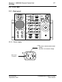
EFP1685 / CCU1686
ON AIR
1
SHORT CABLE
2
GEN
LOCK
SYNC. FAIL.
CAM
ENG
RETURN
VIDEO IN
+12V
-30V
ON
I
STATUS
REMOTE
PRG
SYNC. OUT
flH
BUSY
FAIL
OVERLOAD
CABLE OPEN
MAINS
O
ON LINE
CAM
RCP
MCP
flSC
I min
PROD
R OUT
LOW VOLT
+12V
+300V
AUX
0
G OUT
CAM.HEAD
CALL
RCP
+230VDC
B OUT
MCP
CAM
flSC/H
STEREO
INTERCOM
VIDEO
PAL
ENCODER
CCU
CAMERA
-30V
TRIAX CAM FAIL
OPEN OFF +300V
1
NUMBER
4-2-2
ENCODER
APCM
POWER
+12V
OVER UNDER FAIL
LOAD LOAD +12V
CAM
ON
CAMERA
POWER
ON FAIL
CAMERA
POWER
CCU
POWER
CCU
POWER
MAINS
RECTIFIER
O
TRIAX
CCU
CHROMA
LEVEL
ENG
CAM
I
OFF
MAINS
ON AIR
1
PRG
SYNC. OUT
SYNC. FAIL.
2
GEN
LOCK
SHORT CABLE
RETURN
VIDEO IN
STATUS
REMOTE
ENG
CAM
BUSY
flH
ON LINE
R OUT
MCP
RCP
CAM
G OUT
flSC
PROD
AUX
0
B OUT
CALL
RCP
MCP
CAM
flSC/H
OFF
TRIAX
STEREO
INTERCOM
ENG
REMOTE
PROD
CCU
CHROMA
LEVEL
ENG
CAM
VIDEO
PROD
PAL
ENCODER
1
NUMBER
4-2-2
ENCODER
APCM
PRG
MIX
ENG
TRACKER
3
2
1
MANUEL D’UTILISATION
USER MANUAL
B1685902AC
Ce document et toute mise à jour et/ou complément d'information, ainsi que leurs copies, ne peuvent en aucun cas être reproduits, ni communiqués à une tierce partie, sans autorisation écrite de
THOMSON broadcast systems.
This document and any updates and/or supplemental information, including any copies thereof, can
not be reproduced, neither communicated to a third party, without written authorisation from
THOMSON broadcast systems.
© 2000
THOMSON
broadcast systems
All rights reserved.
KIT DE MAINTENANCE
MAINTENANCE KIT
B1685 901 :
Manuel de maintenance pour l'EFP1685/CCU1686 livré avec :
• un prolongateur de carte pour le CA85,
• un prolongateur de carte pour le Contrôle de voie 1685 ou 1686,
• un extracteur de carte pour le CA85.
B1685 901 :
Maintenance manual for EFP1685/CCU1686 supplied with:
• one extender board for CA85,
• one extender board for CCU1685 or 1686,
• one board extractor for CA85.
OPTION
OPTION
B1685 310 :
Codeur numérique 10 bits pour contrôle de voie 1685 ou 1686.
B1685 310 :
10 bits digital encoder for CCU1685 or 1686.
3
SOMMAIRE / CONTENTS
SECTION 1 - VERSION FRANÇAISE
CHAPITRE 1
GÉNÉRALITÉS ................................................................................... 9
CHAPITRE 2
INSTALLATION ................................................................................ 17
CHAPITRE 3
CONTRÔLES DE VOIE 1685/1686 .................................................. 53
CHAPITRE 4
ADAPTATEUR ARRIÈRE ................................................................. 77
CHAPITRE 5
EXPLOITATION ................................................................................ 85
CHAPITRE 6
VERSION SPORTCAM TTV1657D .................................................. 95
B1685902AC
THOMSON
4
SECTION 2 - ENGLISH VERSION
CHAPTER 1
GENERALITY ................................................................................. 121
CHAPTER 2
INSTALLATION .............................................................................. 129
CHAPTER 3
1685/1686 CHANNEL CONTROL UNIT ......................................... 163
CHAPTER 4
REAR ADAPTER ............................................................................ 187
CHAPTER 5
USE ................................................................................................. 195
CHAPTER 6
VERSION SPORTCAM TTV1657D ................................................ 205
B1685902AC
THOMSON
SECTION 1 - Version Française
5
SECTION 1 - VERSION FRANÇAISE
SOMMAIRE
CHAPITRE 1
GÉNÉRALITÉS .................................................................................... 9
1.1 - Pupitres connectables sur l’équipement .................... 11
1.2 - Principes généraux ....................................................... 12
1.2.1 - Principes généraux d’exploitation de l’équipement............. 12
1.2.2 - Configurations d’exploitation................................................. 14
CHAPITRE 2
INSTALLATION ................................................................................. 17
2.1 - Montage en baie ............................................................ 19
2.1.1 - Montage en coffret 4U 19" de 2 CCUS 1686.......................... 19
2.2 - Alimentation secteur..................................................... 22
2.2.1 - CCU1685................................................................................... 22
2.2.2 - CCU1686................................................................................... 23
2.3 - Configuration Audio .................................................... 25
2.3.1 - Son ambiance stéréo .............................................................. 25
2.3.2 - Interphonie et son "RETOUR PROGRAMME"....................... 27
2.3.3 - Dispositif RTS .......................................................................... 34
2.4 - Configuration Vidéo ...................................................... 36
2.4.1 - Choix "RGB/composantes" des signaux vidéo de sortie.... 36
2.4.2 - Choix "avec ou sans signaux de synchronisation" des signaux
vidéo vert de sortie............................................................................. 37
2.4.3 - Choix "Y/Codé" du signal de contrôle PM en sortie du Contrôle
de Voie ................................................................................................. 37
2.4.4 - Calibration des signaux de synchronisation en PAL ou NTSC
(carte VIDEO PIP)................................................................................ 38
B1685902AC
Septembre 2000
THOMSON EFP1685 / CCU1686
Manuel utilisateur
6
SECTION 1 - Version Française
2.4.5 - Génération de la vidéo "MIX"................................................. 38
2.4.6 - Commutateur "EXT SELECT" du CA 85................................ 38
2.5 - Mise en phase de l'équipement.................................... 39
2.5.1 - Phasage horizontal et phasage de la sous-porteuse .......... 39
2.5.2 - Phasage de la vidéo numérique ............................................ 39
2.6 - Pupitre d’exploitation.................................................... 40
2.6.1 - Câble de liaison OCP CCU ..................................................... 40
2.6.2 - Numérotation des pupitres, choix de la priorité .................. 41
2.6.3 - Adaptation d'impédance ........................................................ 41
2.6.4 - Alimentation des pupitres ...................................................... 41
2.6.5 - Connection d’un pupitre en face avant du Contrôle de Voie 41
2.7 - Numérotation du contrôle de voie (utilisation avec un
MCP)........................................................................................ 42
2.7.1 - Carte APCM version 0............................................................ 42
2.7.2 - Carte APCM version 1............................................................ 43
2.8 - Adaptation aux signalisations d’antenne principale et
d’antenne secondaire dans le contrôle de voie.................. 44
2.8.1 - Carte APCM version 0............................................................. 44
2.8.2 - Carte APCM version 1............................................................. 45
2.9 - Choix "avec ou sans caractères sur la vidéo de contrôle
PM".......................................................................................... 46
2.10 - Sélection de la vidéo numérique en test ................... 47
2.10.1 - Signal disponible sur les sorties numériques en fonction des
commandes "BARS" et "PM" du pupitre ......................................... 47
2.11 - Gestion du CALL ......................................................... 49
2.12 - Mémorisation du MASTER BLACK en SCENE FILE. 49
2.13 - Vitesse de transmission CCU - pupitre ..................... 49
2.14 - Choix du standard 525 ou 625 lignes ........................ 50
2.15 - Implantation des cartes APCM version 0 et 1.......... 51
THOMSON EFP1685 / CCU1686
Manuel utilisateur
B1685902AC
Septembre 2000
SECTION 1 - Version Française
7
CHAPITRE 3
CONTRÔLES DE VOIE 1685/1686 ................................................... 53
3.1 - CCU1685 ........................................................................ 55
3.1.1 - Face arrière .............................................................................. 55
3.1.2 - Face avant ................................................................................ 62
3.2 - CCU1686 ........................................................................ 67
3.2.1 - Face arrière .............................................................................. 67
3.2.2 - Face avant ................................................................................ 73
CHAPITRE 4
ADAPTATEUR ARRIÈRE.................................................................. 77
4.1 - Face arrière.................................................................... 79
4.1.1 - Connecteurs............................................................................. 79
4.1.2 - Commandes et signalisations................................................ 82
4.2 - Côté gauche................................................................... 83
4.2.1 - Commandes et signalisations................................................ 83
CHAPITRE 5
EXPLOITATION ................................................................................. 85
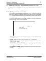
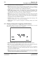
5.1 - Description des affichages en sortie CCU.................. 87
5.1.1 - Affichage à la mise sous tension........................................... 87
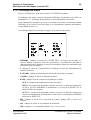
5.1.2 - Affichage de la configuration du ou des pupitre(s) ............. 88
5.1.3 - Affichages d'alarme................................................................. 88
5.1.4 - Affichage des status ............................................................... 89
5.1.5 - Affichage d'exploitation .......................................................... 90
5.1.6 - Affichage suite au déclenchement de la balance des noirs 92
5.1.7 - Affichage suite au déclenchement de la balance des blancs 93
5.2 - Les fonctions Cadreur .................................................. 94
B1685902AC
Septembre 2000
THOMSON EFP1685 / CCU1686
Manuel utilisateur
8
SECTION 1 - Version Française
CHAPITRE 6
VERSION SPORTCAM TTV1657D.................................................... 95
6.1 - Installation...................................................................... 97
6.1.1 - Montage d’un objectif lourd ................................................... 97
6.1.2 - Montage de la caméra avec un objectif lourd ...................... 98
6.1.3 - Montage avec un objectif léger............................................ 100
6.1.4 - Montage du viseur 17 cm ..................................................... 102
6.1.5 - Montage du support script................................................... 103
6.2 - Description................................................................... 104
6.2.1 - Description des connecteurs et commutateurs du boîtier inférieur du châssis "SPORTCAM"....................................................... 105
6.2.2 - Câbles livrés aves le châssis "SPORTCAM"...................... 109
6.2.3 - Clavier arrière ........................................................................ 113
6.2.4 - Viseur N/B 17 cm................................................................... 114
THOMSON EFP1685 / CCU1686
Manuel utilisateur
B1685902AC
Septembre 2000
Chapitre 1 - Généralités
9
Chapitre 1
Généralités
1.1 - Pupitres connectables sur l’équipement .................... 11
1.2 - Principes généraux ....................................................... 12
1.2.1 - Principes généraux d’exploitation de l’équipement.............................. 12
1.2.1.1 - Contrôle technique à partir de la caméra (maintenance)................. 12
1.2.1.2 - Contrôle à partir d'un pupitre ........................................................... 12
1.2.2 - Configurations d’exploitation................................................................ 14
1.2.2.1 - Fonctionnement avec le(s) pupitre(s) OCP40 / OCP42................... 14
1.2.2.2 - Fonctionnement avec un système centralisé MCP.......................... 15
B1685902AC
Septembre 2000
THOMSON EFP1685 / CCU1686
Manuel utilisateur
10
THOMSON EFP1685 / CCU1686
Manuel utilisateur
Chapitre 1 - Généralités
B1685902AC
Septembre 2000
Chapitre 1 - Généralités
Pupitres connectables sur l’équipement
11
1.1 - PUPITRES CONNECTABLES SUR L’ÉQUIPEMENT
La caméra TTV1657 ou TTV1657D connectée sur le système EFP1685/CCU1686
s'exploite avec les pupitres OCP40 / OCP42. Les commandes de plusieurs caméras
peuvent être centralisées en utilisant un MCP (Master Control Panel).
Se référer aux notices spécifiques à chaque pupitre..
PRE
VIEW
LOCK
ACTIV
ON AIR 1
CCU STATUS
BARS
PRE
VIEW
ON
AIR 2
SETTING
CALL
LOCK
ACTIV
ON AIR 1
CCU STATUS
BARS
ON
AIR 2
PRE
SETTING
VIEW
CALL
LOCK
F1
F2
F3
F4
F1
F2
F3
ON
AIR 2
CCU STATUS
BARS
SETTING
F1
F2
F3
F4
CALL
F4
STORE G
EXIT
ON AIR 1
ACTIV
G1
G2
G3
G4
EXIT
EXIT
CAM
1 - 5
CAM
16 - 20
ON AIR
1
2
NEXT
ON AIR
1
2
1
16
2
17
3
18
NEXT
CTRL
CTRL
DIAG
DIAG
NEXT
CTRL
DIAG
PRESET
GAIN
FILTERS
DETAIL
STORE
DFZ
BLACK
COLOUR
RECALL
KNEE
SHUTTER
GAMMA
PRESET
SKIN
OTHERS
GAIN
FILTERS
DETAIL
STORE
DFZ
BLACK
COLOUR
RECALL
KNEE
SHUTTER
GAMMA
SKIN
MEMORY
CAM
4
19
PRESET
GAIN
FILTERS
DETAIL
5
20
STORE
DFZ
BLACK
COLOUR
RECALL
KNEE
SHUTTER
GAMMA
6 - 10
CAM
21 - 24
ON AIR
1
2
BLACK BAL WHITE BAL
BLACK BAL WHITE BAL
ON AIR
1
2
6
21
7
22
8
23
9
24
SKIN
MEMORY
BLACK BAL WHITE BAL
LIMIT
LIMIT
LIMIT
LIMIT
LIMIT
ASSIGNED
ASSIGNED
GAIN
ASSIGNED
ASSIGNED
LIMIT
ASSIGNED
GAIN
GAIN
ASSIGNED
ASSIGNED
ASSIGNED
ASSIGNED
ENABLE
BLACK
AUTO IRIS
FINE
ADJUST
ENABLE
BLACK
AUTO IRIS
FINE
ADJUST
ENABLE
CAM
EXTENDER
EXTENDER
ASSIGNED
10
BLACK
FINE
AUTO IRIS
ADJUST
SELECTION
11 - 15
ON AIR
1
2
11
ALL
EXTENDER
BLACK
LEVEL
12
IRIS
GROUP
IRIS
13
BLACK
LEVEL
OCP 42
OCP40
B1685902AC
Septembre 2000
MASTER
TRANSFER
BLACK
LEVEL
OCP42
14
READ
15
WRITE
IRIS
MSP
OCP 50
MCP
THOMSON EFP1685 / CCU1686
Manuel utilisateur
12
Chapitre 1 - Généralités
Principes généraux
1.2 - PRINCIPES GÉNÉRAUX
1.2.1 - Principes généraux d’exploitation de l’équipement
1.2.1.1 - Contrôle technique à partir de la caméra (maintenance)
L'opérateur situé à la tête de caméra peut prendre le contrôle de l'équipement en ouvrant la
porte gauche de la caméra et en appuyant sur la flèche gauche "<" du miniclavier. Les principales commandes techniques et d'exploitation de la caméra lui sont accessibles (se
référer à la notice de maintenance de la caméra).
Sur le pupitre, les commandes sont inhibées (le voyant "LOCK" est allumé). Les signalisations encore actives renseignent l'opérateur du pupitre sur l'état de l'équipement.
1.2.1.2 - Contrôle à partir d'un pupitre
1.2.1.2.1 - Principe de fonctionnement des pupitres
Commandes potentiométriques
Pour valider une commande potentiométrique (Noirs partiels, Gains partiels, Niveau de
Contour, Niveau de Saturation,... sauf modification de l'ouverture de l'iris d'objectif) ou
pour valider les commandes de contrôle vidéo (PM), il faut appuyer sur la touche "LOCK"
pour déverrouiller le pupitre (voyant"LOCK" éteint).
Les paramètres accessibles par les commandes potentiométriques prennent des valeurs
finales qui résultent d'une suite d'ordres provenant éventuellement de plusieurs pupitres.
Chaque action modifie la dernière valeur enregistrée.
Commandes "Tout ou Rien" et commande d'ouverture d'objectif
Pour changer une commande "Tout ou Rien" ou pour modifier l'ouverture de l'iris
d'objectif, il faut appuyer successivement sur les touches "LOCK" puis "ACTIV" du
pupitre. Les commandes potentiométriques et les commandes de contrôle vidéo sont aussi
validées.
L'ouverture de l'iris d'objectif est fixée par la commande du dernier pupitre placé en mode
"ACTIV". Cette fonction n'est pas partagée. Il faut donc tenir compte du fait qu'à la prise
de contrôle de l'équipement par un pupitre en mode "ACTIV", la luminosité de l'image
peut varier notablement suivant la position de la monocommande d'ouverture d'iris.
Un ordre de priorité est établi entre les différents pupitres (suivant des commandes internes
effectuées à l'installation) : un pupitre ne peut pas changer les commandes "Tout ou Rien"
ou l'ouverture de l'iris si un pupitre de degré supérieur est en mode "ACTIV".
THOMSON EFP1685 / CCU1686
Manuel utilisateur
B1685902AC
Septembre 2000
Chapitre 1 - Généralités
Principes généraux
13
1.2.1.2.2 - Branchement du (des) pupitre(s) tributaire(s) du Contrôle de voie
Le (les) pupitre(s) OCP est (sont) raccordé(s) à la prise "RCP" du Contrôle de Voie. On dit
qu'il(s) est (sont) tributaire(s) du Contrôle de Voie.
Le pupitre le plus éloigné du Contrôle de Voie doit être le seul à fermer la liaison SMPTE
sur 150=Ω.
Dans sa configuration maximale, un Contrôle de Voie peut être équipé de 3 pupitres
OCP40 / OCP42.
1.2.1.2.3 - Alimentation des pupitres
La tension d'alimentation 11 Vdc à 14 Vdc peut être fournie par le Contrôle de voie disponible sur:
• CCU 1685: la prise RCP POWER OUT ou RCP lorsqu'un seul pupitre est utilisé. Dans
les autres cas, il faut utiliser une unité externe "PPU" (PANEL POWER UNIT) capable
d'alimenter 8 pupitres.
• CCU 1686: la prise RCP lorsqu'un seul pupitre est utilisé. Dans les autres cas, il faut
utiliser une unité externe "PPU" (PANEL POWER UNIT) capable d'alimenter 8
pupitres.
L'utilisation de l'unité externe "PPU" est nécessaire si la distance OCP CCU est supérieure
à 100 mètres. Se référer au chapitre 2 paragraphe 2.6.4 -Alimentation des pupitres.
B1685902AC
Septembre 2000
THOMSON EFP1685 / CCU1686
Manuel utilisateur
14
Chapitre 1 - Généralités
Principes généraux
1.2.2 - Configurations d’exploitation
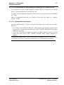
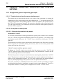
1.2.2.1 - Fonctionnement avec le(s) pupitre(s) OCP40 / OCP42
MONITORING
EXT
CALL
SEL
12v
off
48v
V/F
VIDEO
I
mix
cam
ext
MIC 2
PHANTOM
O
POWER
SPORTCAM
MONITORING
EXT
CALL
SEL
12v
off
48v
V/F
VIDEO
I
mix
cam
ext
MIC 2
PHANTOM
O
POWER
1657 ou 1657D + CA85
Si plusieurs pupitres ou si la distance
CCU OCP est supérieure à 100 mètres
PPU
PM
RCP
Inverseur
sur 150 Ω
CCU1685
OCP40
OCP42
OCP40
OCP42
OCP40
OCP42
CCU1686
THOMSON EFP1685 / CCU1686
Manuel utilisateur
B1685902AC
Septembre 2000
Chapitre 1 - Généralités
Principes généraux
15
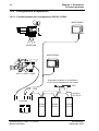
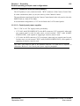
1.2.2.2 - Fonctionnement avec un système centralisé MCP
MONITORING
EXT
CALL
SEL
12v
off
48v
V/F
I
VIDEO
mix
cam
ext
MIC 2
PHANTOM
O
POWER
SPORTCAM
MONITORING CENTRALISE
EXT
CALL
SEL
12v
off
48v
V/F
VIDEO
I
mix
cam
ext
MIC 2
PHANTOM
O
POWER
1657 ou 1657D + CA85
PM
PM des
autres
CCUs
MCP
Grille de
monitoring
Inverseur
sur 150 Ω
RCP
MCP des
autres
CCUs
Commande de grille
CCU1685
CCU1686
OCP40
OCP42
MSP
OCP50
MCP
B1685902AC
Septembre 2000
THOMSON EFP1685 / CCU1686
Manuel utilisateur
16
THOMSON EFP1685 / CCU1686
Manuel utilisateur
Chapitre 1 - Généralités
Principes généraux
B1685902AC
Septembre 2000
Chapitre 2 - Installation
17
Chapitre 2
Installation
2.1 - Montage en baie ............................................................ 19
2.1.1 - Montage en coffret 4U 19" de 2 CCUS 1686....................................... 19
2.2 - Alimentation secteur..................................................... 22
2.2.1 - CCU1685 ............................................................................................. 22
2.2.2 - CCU1686 ............................................................................................. 23
2.3 - Configuration Audio .................................................... 25
2.3.1 - Son ambiance stéréo........................................................................... 25
2.3.2 - Interphonie et son "RETOUR PROGRAMME" .................................... 27
2.3.2.1 - Interphonie cadreur.......................................................................... 27
2.3.2.1.1 - Liaisons cadreur vers PROD et ENG..................................... 27
a -Type de microphone ..................................................................... 27
b -Sélection ENG - PROD ................................................................. 28
c -Niveau et type des liaisons d’interphonie CAM vers PROD ou CAM vers
ENG .................................................................................................. 29
2.3.2.1.2 - Liaisons PROD et ENG vers le cadreur................................. 30
2.3.2.2 - Interphonie sur le CCU .................................................................... 32
2.3.2.2.1 - Microphone ............................................................................ 32
a -Type de microphone ..................................................................... 32
b -Sélection OFF/CAM/CAM+ENG ................................................... 32
2.3.2.2.2 - Liaisons CAM, PROD, PROG et ENG vers le CCU............... 33
2.3.3 - Dispositif RTS ...................................................................................... 34
2.3.3.1 - Liaisons Cadreur vers RTS1 et RTS2.............................................. 34
2.3.3.2 - Liaisons RTS1 et RTS2 vers Cadreur.............................................. 35
2.4 - Configuration Vidéo ...................................................... 36
2.4.1 - Choix "RGB/composantes" des signaux vidéo de sortie ..................... 36
2.4.2 - Choix "avec ou sans signaux de synchronisation" des signaux vidéo vert de
sortie ............................................................................................................... 37
2.4.3 - Choix "Y/Codé" du signal de contrôle PM en sortie du Contrôle de Voie 37
2.4.4 - Calibration des signaux de synchronisation en PAL ou NTSC (carte VIDEO
PIP) ................................................................................................................. 38
2.4.5 - Génération de la vidéo "MIX"............................................................... 38
2.4.6 - Commutateur "EXT SELECT" du CA 85 ............................................. 38
2.5 - Mise en phase de l'équipement ................................... 39
B1685902AC
Septembre 2000
THOMSON EFP1685 / CCU1686
Manuel utilisateur
18
Chapitre 2 - Installation
2.5.1 - Phasage horizontal et phasage de la sous-porteuse ........................... 39
2.5.1.1 - Phasage horizontal .......................................................................... 39
2.5.1.2 - Phasage de la sous-porteuse .......................................................... 39
2.5.2 - Phasage de la vidéo numérique .......................................................... 39
2.6 - Pupitre d’exploitation.................................................... 40
2.6.1 - Câble de liaison OCP CCU ..................................................................
2.6.2 - Numérotation des pupitres, choix de la priorité....................................
2.6.3 - Adaptation d'impédance.......................................................................
2.6.4 - Alimentation des pupitres.....................................................................
2.6.5 - Connection d’un pupitre en face avant du Contrôle de Voie................
40
41
41
41
41
2.7 - Numérotation du contrôle de voie (utilisation avec un
MCP)........................................................................................ 42
2.7.1 - Carte APCM version 0 ........................................................................ 42
2.7.2 - Carte APCM version 1 ........................................................................ 43
2.8 - Adaptation aux signalisations d’antenne principale et
d’antenne secondaire dans le contrôle de voie.................. 44
2.8.1 - Carte APCM version 0 ......................................................................... 44
2.8.2 - Carte APCM version 1 ......................................................................... 45
2.9 - Choix "avec ou sans caractères sur la vidéo de contrôle
PM".......................................................................................... 46
2.10 - Sélection de la vidéo numérique en test ................... 47
2.10.1 - Signal disponible sur les sorties numériques en fonction des commandes
"BARS" et "PM" du pupitre .............................................................................. 47
2.10.1.1 - Le commutateur RC1 est en position exploitation.......................... 47
2.10.1.2 - Le commutateur RC1 est sur une position test .............................. 48
2.11 - Gestion du CALL ......................................................... 49
2.12 - Mémorisation du MASTER BLACK en SCENE FILE. 49
2.13 - Vitesse de transmission CCU - pupitre ..................... 49
2.14 - Choix du standard 525 ou 625 lignes ........................ 50
2.15 - Implantation des cartes APCM version 0 et 1.......... 51
THOMSON EFP1685 / CCU1686
Manuel utilisateur
B1685902AC
Septembre 2000
Chapitre 2 - Installation
Montage en baie
19
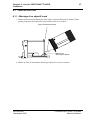
2.1 - MONTAGE EN BAIE
Pour un montage en baie le contrôle de voie doit être posé sur des glissières et non
uniquement fixé par sa face avant.
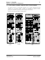
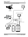
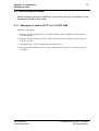
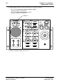
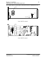
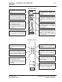
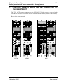
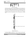
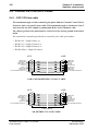
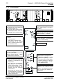
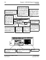
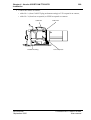
2.1.1 - Montage en coffret 4U 19" de 2 CCUS 1686
Se référer aux figures.
1. Déposer l'oreille droite du CCU 1686 devant être placé à gauche en dévissant ses
2 vis de fixation.
2. Déposer l'oreille gauche du CCU 1686 devant être placé à droite en dévissant ses
2 vis de fixation.
3. Positionner les 2 CCUs à l'intérieur du coffret 4U 19".
4. Sur l'arrière du coffret visser les 2 vis de fixation des CCUs (ces vis sont livrées avec
le coffret).
B1685902AC
Septembre 2000
THOMSON EFP1685 / CCU1686
Manuel utilisateur
20
Chapitre 2 - Installation
Montage en baie
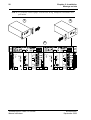
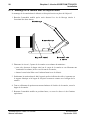
NOTA : Le poids du coffret équipé est d'environ 40 kg. Manipuler l'ensemble avec
précaution.
1
2
CCU
CCU
POWER
+12V
OVER UNDER FAIL
LOAD LOAD +12V
CAM
ON
CAMERA
POWER
ON FAIL
CCU
POWER
CCU
CAMERA
-30V
TRIAX CAM FAIL
OPEN OFF +300V
POWER
+12V
MAINS
OVER UNDER FAIL
LOAD LOAD +12V
CAM
ON
CAMERA
POWER
ON FAIL
CCU
POWER
MAINS
ON AIR
ON AIR
1
PRG
SYNC. OUT
SYNC. FAIL.
RETURN
VIDEO IN
PRG
SYNC. OUT
STATUS
CAM
SYNC. FAIL.
flH
RETURN
VIDEO IN
STATUS
REMOTE
BUSY
ENG
CAM
CAM
G OUT
ON LINE
MCP
RCP
R OUT
G OUT
PROD
flSC
PROD
AUX
AUX
0
B OUT
B OUT
CALL
MCP
flSC/H
OFF
CCU
CHROMA
LEVEL
ENG
CAM
STEREO
INTERCOM
CALL
RCP
CAM
TRIAX
MCP
RCP
CAM
flSC
0
BUSY
flH
ON LINE
R OUT
2
GEN
LOCK
SHORT CABLE
REMOTE
ENG
1
2
GEN
LOCK
SHORT CABLE
O
TRIAX CAM FAIL
OPEN OFF +300V
I
CAMERA
-30V
I
CCU
O
3
VIDEO
PAL
ENCODER
THOMSON EFP1685 / CCU1686
Manuel utilisateur
MCP
flSC/H
1
OFF
APCM
TRIAX
STEREO
INTERCOM
CCU
CHROMA
LEVEL
ENG
CAM
NUMBER
4-2-2
ENCODER
RCP
CAM
VIDEO
PAL
ENCODER
1
NUMBER
4-2-2
ENCODER
APCM
B1685902AC
Septembre 2000
Chapitre 2 - Installation
Montage en baie
21
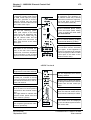
4
VIDEO OUTPUT
INTERCOM
VIDEO OUTPUT
PGM IN
PIX
N
MIC 1 OUT
1
MIC 2 OUT
ENC. OUT
MIX VIDEO
ENC. OUT
OUT
B-Y
IN
RET 3
RET 4
RET 1
RET 2
I
P
U
PROMPTER
GEN LOCK
2
SERIAL DIGITAL OUTPUT
1
C
L
RET 4
RET 1
RET 2
T
PROMPTER
GEN LOCK
2
C
N
MIC REM
RCP
MIC REM
MCP
ON AIR
T
R
O
IN
RET 3
O
RCP
T
4
2
N
P
U
O
3
MIX VIDEO
OUT
B
2
N
N
MIC 2 OUT
ENGINER
G
B
1
MIC 1 OUT
1
ENGINER
Y
B-Y
T
AUDIO
R-Y
Y
SERIAL DIGITAL OUTPUT
PGM IN
PRODUCER
R
AUDIO
G
I
INTERCOM
PIX
N
PRODUCER
R
R-Y
3
MCP
ON AIR
4
R
O
L
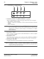
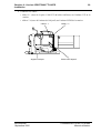
Vis de fixation des contrôles de voie
B1685902AC
Septembre 2000
THOMSON EFP1685 / CCU1686
Manuel utilisateur
22
Chapitre 2 - Installation
Alimentation secteur
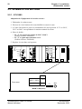
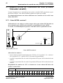
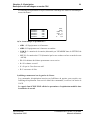
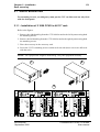
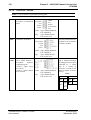
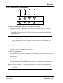
2.2 - ALIMENTATION SECTEUR
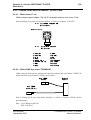
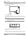
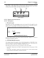
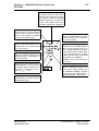
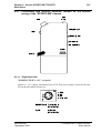
2.2.1 - CCU1685
Adaptation de l’équipement à la tension secteur :
1. Débrancher le cordon secteur.
2. Dévisser la vis de fixation de la carte MAINS et extraire la carte.
3. A l’aide d’un tournevis, placer le commutateur S02 sur la position 115 V ou 220 V,
230 V ou 240 V correspondant à la tension nominale du réseau.
4. Placer le fusible :
• F1 = T 2,5 A pour une tension de 220 V à 240 V.
(Fusible référence T9000667).
• F1 = T 4 A pour une tension de 110 V.
(Fusible référence T9000669).
5. Replacer la carte dans son logement.
ON AIR
1
SHORT CABLE
2
GEN
LOCK
SYNC. FAIL.
CAM
ENG
RETURN
VIDEO IN
+12V
REMOTE
PRG
SYNC. OUT
-30V
ON
I
STATUS
flH
BUSY
FAIL
OVERLOAD
CABLE OPEN
MAINS
O
ON LINE
CAM
RCP
MCP
flSC
G OUT
I min
PROD
R OUT
CAM.HEAD
LOW VOLT
+12V
+300V
AUX
0
CALL
RCP
+230VDC
B OUT
MCP
CAM
flSC/H
OFF
TRIAX
STEREO
INTERCOM
CCU
CHROMA
LEVEL
ENG
CAM
VIDEO
1
NUMBER
4-2-2
PAL
ENCODER ENCODER
APCM
CAMERA
POWER
CCU
POWER
MAINS
RECTIFIER
F1
Face avant
240 V
T 2,5 A
220 V - 230 V
110 V
T4A
F1
S02
I
"MAIN" PCB (CCU)
THOMSON EFP1685 / CCU1686
Manuel utilisateur
B1685902AC
Septembre 2000
Chapitre 2 - Installation
Alimentation secteur
23
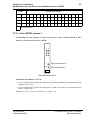
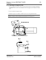
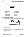
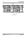
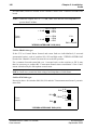
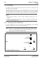
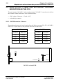
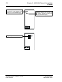
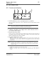
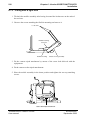
2.2.2 - CCU1686
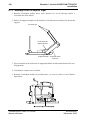
Adaptation de l’équipement à la tension secteur :
1. Débrancher le cordon secteur.
2. Déposer la plaque supérieure du CCU en dévissant ses 5 vis de fixation.
Plaque supérieure
Vis de fixation
3. A l’aide d’un tournevis, placer le commutateur S1 situé sur la carte "MAIN
RECTIFIER" sur la position 115 V ou 220 V, 230 V ou 240 V correspondant à la
tension nominale du réseau.
S1
Carte
MAINS RECTIFIER
B1685902AC
Septembre 2000
THOMSON EFP1685 / CCU1686
Manuel utilisateur
24
Chapitre 2 - Installation
Alimentation secteur
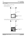
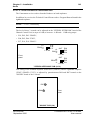
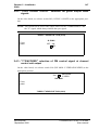
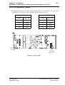
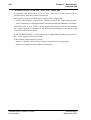
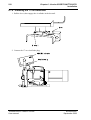
4. Dans l'embase secteur, en face arrière du CCU, placer le fusible :
• F1 = T 2,5 A pour une tension de 220 V à 240 V.
(Fusible référence T9000667).
• F1 = T 4 A pour une tension de 110 V.
(Fusible référence T9000669).
Fusible F1
VIDEO OUTPUT
INTERCOM
PGM IN
PIX
N
PRODUCER
R
AUDIO
R-Y
MIC 1 OUT
1
MIC 2 OUT
ENGINER
G
Y
ENC. OUT
MIX VIDEO
OUT
B
B-Y
I
2
IN
RET 3
RET 4
RET 1
RET 2
PROMPTER
GEN LOCK
N
P
U
SERIAL DIGITAL OUTPUT
1
T
2
C
O
N
RCP
MIC REM
MCP
ON AIR
T
3
4
R
O
L
5. Reposer la plaque supérieure du CCU.
THOMSON EFP1685 / CCU1686
Manuel utilisateur
B1685902AC
Septembre 2000
Chapitre 2 - Installation
Configuration Audio
25
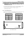
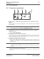
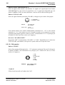
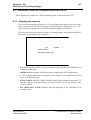
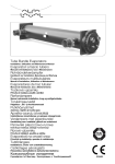
2.3 - CONFIGURATION AUDIO
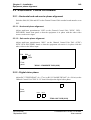
2.3.1 - Son ambiance stéréo
L'équipement offre la possibilité de connecter 2 microphones : le premier sur la prise
XLR3 situé sur la poignée de la caméra, et le second sur la prise XLR3 situé sur la face
arrière du CA85.
1. Le microphone connecté sur la tête de caméra reçoit une alimentation fantôme de
12 V. Son niveau de sortie nominal doit être de - 60 dB ou - 40 dB :
• pour un niveau de sortie du microphone de - 60 dB placer le switch S2 situé sur
l’interconnexion du CA85 sur la position : 0 dB,
• pour un niveau de sortie du microphone de - 40 dB placer le switch S2 situé sur
l'interconnexion du CA85 sur la position : - 20 dB.
2. Le microphone connecté sur le CA85 peut être du type dynamique ou électrostatique.
Son niveau de sortie nominal doit être de - 60 dB ou - 40 dB :
• dans le 1er cas (microphone dynamique), placer le commutateur "PHANTOM
POWER" situé sur le côté gauche du CA85 sur la position OFF,
• dans le 2ème cas (microphone électrostatique), placer ce même commutateur sur la
position 48 V ou 12 V correspondant à la tension d’alimentation du microphone (se
reporter à la Notice du microphone),
• pour un niveau de sortie du microphone de - 60 dB placer le switch S3 situé sur
l'interconnexion du CA85 sur la position : 0 dB,
• pour un niveau de sortie du microphone de - 40 dB placer le switch S3 situé sur
l'interconnexion du CA85 sur la position : - 20 dB.
S2
MIC.CAM
0dB
-20dB
MIC.CA
SOUND
J15
J13
S3
0dB
-20dB
J12
MULTIPLEX
J11
STEREO SOUND
J2
J14
J16
interconnexion CA85 côté cartes enfichables
B1685902AC
Septembre 2000
THOMSON EFP1685 / CCU1686
Manuel utilisateur
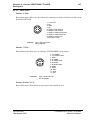
26
Chapitre 2 - Installation
Configuration Audio
CALL
12v
off
EXT
V/F
SEL
VIDEO
I
mix
48v
cam
ext
MIC 2
PHANTOM
O
POWER
Commandes côté gauche
La sensibilité des micros ambiance est télécommandable par une tension continue injectée
à l’arrière du Contrôle de Voie sur la prise "MIC. REM. SENS. IN" (atténuation de 0 dB
pour 0 Volt à - 46,5 dB pour 5 Volts). Cette télécommande est active si les commutateurs
situés en face avant de la carte "STEREO SOUND" dans le CA sont en position "REM"
(Remote). Dans le cas contraire (commutateurs en position "MAN") le gain de chaque
micro est réglable par le potentiomètre associé à chaque commutateur.
Pour accéder à la carte "STEREO SOUND", enlever la porte gauche du CA en dévissant
ses 4 vis de fixation.
MIC
2
LV
STEREO SOUND
MAN REM
"MIC2" micro connecté sur le CA
MIC
1
LV
MAN REM
"MIC1" micro connecté sur la caméra
THOMSON EFP1685 / CCU1686
Manuel utilisateur
B1685902AC
Septembre 2000
Chapitre 2 - Installation
Configuration Audio
27
Le niveau de sortie des Sons "MICRO AMBIANCE" sont réglables sur la carte "STEREO
INTERCOM" du Contrôle de Voie entre - 6 dB et + 12 dB par bond de 6 dB. Le réglage fin
du niveau de sortie caméra se fait par le potentiomètre R02 situé sur la même carte. Le
réglage fin du niveau de sortie du CA85 se fait par le potentiomètre R08.
+ 12 dB
Face
avant
R08
MICRO2 (CA)
+ 12 dB
R02
MICRO1 (CAM)
- 6 0 + 6 dB
E14 E15 E16
- 6 0 + 6 dB
E23 E24 E25
"STEREO INTERCOM" PCB (CCU)
E14 E15 E16
E23 E24 E25
+ 12 dB
+ 6 dB
0 dB
- 6 dB
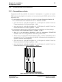
2.3.2 - Interphonie et son "RETOUR PROGRAMME"
Remarque concernant la terminologie :
• "CAM" signifie Micro Cadreur,
• "ENG" signifie Ordres de la salle de Contrôle technique,
• "PROD" signifie Ordres du Réalisateur,
• "PROG" signifie Son Retour Programme,
• "CCU" signifie Micro de l’Opérateur du Contrôle de Voie.
2.3.2.1 - Interphonie cadreur
2.3.2.1.1 - Liaisons cadreur vers PROD et ENG
a - Type de microphone
Suivant le type de microphone utilisé, il faut placer chacun des inverseurs S11, S12 et S13
qui sont situés sur la carte "AUDIO CA85" du CA, sur la position ELECTRET (casque
électrostatique) ou sur la position DYNAMIC (casque électrodynamique).
En position ELECTRET, le CA fournit au microphone par la prise casque-microphone une
tension d’alimentation de + 9 Volts. Cette alimentation est secourue quand la tête de
caméra est mise hors tension. Dans ce cas, la sensibilité du microphone peut être ajustée
par le potentiomètre R04 situé sur la carte "AUDIO CA85".
Le niveau nominal de sortie du microphone doit être compris entre - 20 dB et - 40dB :
• pour un niveau de - 20 dB, mettre l'inverseur S10 situé sur cette même carte sur la
B1685902AC
Septembre 2000
THOMSON EFP1685 / CCU1686
Manuel utilisateur
28
Chapitre 2 - Installation
Configuration Audio
position - 20 dB,
• pour un niveau de - 40 dB mettre l'inverseur S10 sur la position 0 dB.
Accès au circuit "AUDIO CA85"
Enlever la porte gauche du CA85 : le circuit "AUDIO CA85" est fixé sur la face arrière du
CA85.
0dB
S10
-20dB
R04
S12
E
D
E =
Electret
D = Dynamic
S11
S13
D
E
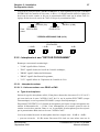
b - Sélection ENG - PROD
Le Cadreur choisit l’interlocuteur ENG (Salle de contrôle technique) ou PROD (Réalisateur) à l’aide du commutateur S02 "PROD/REMOTE/ENG" situé sur le bandeau de
commandes audio sur la face arrière du CA.
NOTA : Si le cavalier E13 situé sur la carte "STEREO INTERCOM" du Contrôle de
Voie est placé sur ENG+PROD, la position ENG ou PROD permet au
Cadreur de parler simultanément aux 2 interlocuteurs.
S02
ENG
REMOTE
PROD
PROD
ENG
PRG
MIX
Commandes audio
THOMSON EFP1685 / CCU1686
Manuel utilisateur
B1685902AC
Septembre 2000
Chapitre 2 - Installation
Configuration Audio
29
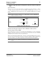
c - Niveau et type des liaisons d’interphonie CAM vers PROD ou CAM vers
ENG
Niveau des liaisons
Dans les 2 cas, le niveau de sortie du Son est réglable par bond de 6 dB entre - 6 dB et
+ 12 dB à l’aide des cavaliers E07, E08, E09 (PROD - INTERCOM1) et E10, E11, E12
(ENG - INTERCOM 2) qui sont situés sur la carte "STEREO INTERCOM" du Contrôle
de Voie.
NOTA : Quand le niveau de sortie est à + 12 dB, veiller à ce que l’impédance de
charge soit supérieure à 5 kΩ.
OUT + 6 E12
0 E11
+ 12 dB
- 6 E10
Face
avant
OUT + 6 E09
0 E08
+ 12 dB
- 6 E07
E13
ENG + PROD
"STEREO INTERCOM" PCB (CCU)
Sélection 2 fils/4 fils pour les liaisons CAM vers PROD ou CAM vers ENG
Type de la liaison CAM vers PROD
Si les liaisons aller et retour CCU vers Régie sont individualisées (2 paires symétriques
blindées), il faut placer chacun des inverseurs S02, S03 et S04 situés sur la carte "STEREO
INTERCOM" du Contrôle de Voie sur la position 4 W.
Dans le cas d’une liaison commune aller - retour sur 1 seule paire blindée, placer ces inverseurs sur 2 W. Il peut être alors nécessaire de reprendre le réglage de R09 "annulation du
retour Son Cadreur" si le Cadreur est gêné par le retour du Son de son microphone.
NOTA : Dans tous les cas, adapter les liaisons par une impédance de charge égale à
600 Ω.
B1685902AC
Septembre 2000
THOMSON EFP1685 / CCU1686
Manuel utilisateur
30
Chapitre 2 - Installation
Configuration Audio
Type de la liaison CAM vers ENG
Procéder de la même manière avec les inverseurs S08, S09, S10 et le potentiomètre R01
"annulation du retour Son Cadreur".
S08 S09
4W
ENG
2W
S10
R01
PROD
Face
avant
R09
4W
2W
S04
S02 S03
"STEREO INTERCOM" PCB (CCU)
2.3.2.1.2 - Liaisons PROD et ENG vers le cadreur
Sur les 2 écouteurs, le Cadreur reçoit les ordres du Réalisateur.
Sur l’écouteur droit, il reçoit en plus le Son "Ordres de la salle de Contrôle technique" +
"Retour Programme".
NOTA : + "CCU" éventuellement.
Le niveau de ces 3 sons est réglable sur la carte "STEREO INTERCOM" du Contrôle de
Voie par bond de 6 dB entre - 6 dB et + 12 dB avec les cavaliers :
• E01, E02, E03 : "PROD",
• E04, E05, E06 : "ENG",
• E17, E18, E19 : "PROG".
+6
PROG 0
-6
OUT
+ 12 dB
E19
E18
E17
+6
ENG 0
-6
Face
avant
+6
PROG 0
-6
OUT
+ 12 dB
OUT
+ 12 dB
E06
E05
E04
E03
E02
E01
"STEREO INTERCOM" PCB (CCU)
THOMSON EFP1685 / CCU1686
Manuel utilisateur
B1685902AC
Septembre 2000
Chapitre 2 - Installation
Configuration Audio
31
Le réglage fin du niveau des Sons de l’écouteur gauche ("PROD") et de l’écouteur droit
("ENG" + "PROD" + "CCU") sont ajustables par les potentiomètres respectifs R08 et R07
qui se trouvent sur la carte "SOUND" du CA.
R07
Face
avant
R08
"SOUND" PCB (CA)
B1685902AC
Septembre 2000
THOMSON EFP1685 / CCU1686
Manuel utilisateur
32
Chapitre 2 - Installation
Configuration Audio
Les niveaux d’écoute des sons "PROD", "ENG", "PROG" sont ajustables individuellement
avec les potentiomètres et commutateur respectifs R01 "PROD", R02 "ENG (PROG)" et
R03 "PRG MIX" qui sont situés sur le bandeau supérieur de la face arrière du CA.
R01
ENG
REMOTE
PROD
R02
PROD
ENG
S03
PRG
MIX
Commandes audio
2.3.2.2 - Interphonie sur le CCU
2.3.2.2.1 - Microphone
a - Type de microphone
Suivant le type de microphone utilisé, il faut placer chacun des cavaliers E20, E21 et E22
qui sont situés sur la carte "STEREO INTERCOM" du Contrôle de Voie, sur la position
ELECTRET (casque électrostatique) ou sur la position DYNAMIC (casque électrodynamique).
Face
avant
E22 E21
E20
DYNAMIC
ELECTRET
"STEREO INTERCOM" PCB (CCU)
En position ELECTRET, le Contrôle de Voie fournit par la prise casque-microphone une
tension d’alimentation de + 9 Volts.
b - Sélection OFF/CAM/CAM+ENG
L’opérateur situé au Contrôle de Voie choisit l’interlocuteur CAM (Cadreur) ou
CAM+ENG (Cadreur et Salle de contrôle technique) à l’aide du commutateur S640
"CAM/OFF/ENG+CAM" situé sur la face avant de la carte "STEREO INTERCOM" du
Contrôle de Voie.
Suivant la sélection, le Son de ce micro est alors ajouté :
• au Son "ENG" et au Son "PROG" à destination du Cadreur (cas de la sélection CAM),
• au Son "ENG" et au Son "PROG" à destination du Cadreur et au Son "CAM" à
destination de la salle de Contrôle technique (cas de la sélection "CAM"+"ENG").
THOMSON EFP1685 / CCU1686
Manuel utilisateur
B1685902AC
Septembre 2000
Chapitre 2 - Installation
Configuration Audio
33
2.3.2.2.2 - Liaisons CAM, PROD, PROG et ENG vers le CCU
Sur l’écouteur gauche, l’opérateur du Contrôle de Voie reçoit le mélange des Sons PROG
et CAM.
Sur l’écouteur droit, il reçoit le mélange des Sons PROD et ENG.
Ces 4 Sons PROG, CAM, PROD, ENG sont ajustables individuellement par les potentiomètres respectifs R630 "PRG", R620 "CAM", R600 "PROD", R610 "ENG" qui sont situés
sur la face avant de la carte "STEREO INTERCOM" du Contrôle de Voie.
B1685902AC
Septembre 2000
THOMSON EFP1685 / CCU1686
Manuel utilisateur
34
Chapitre 2 - Installation
Configuration Audio
2.3.3 - Dispositif RTS
L’équipement est doté d’un système RTS qui permet au Cadreur de communiquer avec
d’autres usagers par 2 liaisons RTS.
Pour rendre opérationnel ce dispositif, il faut placer les inverseurs S05, S06, S07 et S14 qui
sont situés sur la carte "STEREO INTERCOM" du Contrôle de Voie sur la position RTS
pour se connecter sur la ligne RTS1 et faire de même avec les inverseurs S11, S12, S13 et
S15 pour se connecter sur la ligne RTS2.
NOTAS :
1. Lorsque la liaison RTS1 (RTS2) est utilisée, la liaison interphone "ENG" ("PROD")
est indisponible.
2. Les organes de réglage R01, R09 et E01 à E06 sont communs aux liaisons RTS et
aux interphones ENG et PROD.
2.3.3.1 - Liaisons Cadreur vers RTS1 et RTS2
Pour parler aux usagers de la ligne RTS1, le Cadreur doit placer le commutateur
"PROD/ENG" sur la position PROD. Pour parler aux usagers de la ligne RTS2, il doit le
placer sur la position ENG.
NOTA : Si le cavalier E13 de la carte "STEREO INTERCOM" du Contrôle de Voie
est placé sur ENG+PROD, la sélection ENG ou PROD permet au Cadreur de
parler sur les 2 lignes simultanément.
S12
RTS1 S11 S13
ENG
NORM
Face
avant
E13
S06
RTS2
ENG
PROD
+ PROD
NORM
S05 S07
"STEREO INTERCOM" PCB (CCU)
THOMSON EFP1685 / CCU1686
Manuel utilisateur
S14
ON OFF
S15
ON
OFF
B1685902AC
Septembre 2000
Chapitre 2 - Installation
Configuration Audio
35
2.3.3.2 - Liaisons RTS1 et RTS2 vers Cadreur
Le Cadreur reçoit sur l’écouteur gauche le Son provenant de la ligne RTS1 et sur l’écouteur droit le Son provenant de la ligne RTS2 auquel s’ajoutent éventuellement les Sons
"PROG" et "CCU".
Exemple d’installation audio du type RTS
B1685902AC
Septembre 2000
THOMSON EFP1685 / CCU1686
Manuel utilisateur
36
Chapitre 2 - Installation
Configuration Vidéo
2.4 - CONFIGURATION VIDÉO
NOTA : Deux types de carte "VIDEO" équipent les CCU1685 et 1686.
La version 1 est équipée de la fonction "PIP" (picture in picture) utilisée avec les caméras
de studio. Elle est identifiable par la présence d'un quartz sur sa face composants.
2.4.1 - Choix "RGB/composantes" des signaux vidéo de sortie
NOTA : Le CCU1686 ne possédant qu'un groupe de sorties vidéo, les sorties "VIDEO
OUT 1" sont seules utilisées.
Pour les vidéos de sortie "VIDEO OUT 1" du contrôle de voie placer sur la carte vidéo les
commutateurs S04 (R/CR), S6 (G/Y), S08 (B/CB) sur la position convenable.
Pour les vidéos de sortie "VIDEO OUT 2" du contrôle de voie placer sur la carte vidéo les
commutateurs S05 (R/CR), S7 (G/Y), S09 (B/CB) sur la position convenable.
"VIDEO"/"VIDEO PIP" PCB (CCU)
Face
avant
THOMSON EFP1685 / CCU1686
Manuel utilisateur
VIDEO 1
VIDEO 2
R
S4
R
S5
CR
CR
G+(SYNC)
Y
S6
G
Y
S7
CB
B
S8
CB
B
S9
B1685902AC
Septembre 2000
Chapitre 2 - Installation
Configuration Vidéo
37
2.4.2 - Choix "avec ou sans signaux de synchronisation" des signaux
vidéo vert de sortie
Placer sur la carte vidéo le commutateur S03 (G.SYNC : ON/OFF) sur la position convenable.
NOTA : Ce commutateur n'a aucune action si les vidéos de sortie sont les "COMPOSANTES", le signal "Y" comportant toujours le signal de synchronisation.
"VIDEO"/"VIDEO PIP" PCB (CCU)
G. SYNC
Face
avant
OFF ON
S3
2.4.3 - Choix "Y/Codé" du signal de contrôle PM en sortie du Contrôle
de Voie
Placer sur la carte vidéo le commutateur S10 (PIX MON : Y.VIDEO ENCODED) sur la
position convenable.
ENCODED
Y VIDEO
PIX MON
S10
Face
avant
"VIDEO"/"VIDEO PIP" PCB (CCU)
B1685902AC
Septembre 2000
THOMSON EFP1685 / CCU1686
Manuel utilisateur
38
Chapitre 2 - Installation
Configuration Vidéo
2.4.4 - Calibration des signaux de synchronisation en PAL ou NTSC
(carte VIDEO PIP)
Placer les commutateurs S13, S14, S15 sur la position correspondant au standard d'exploitation.
S13
S15
Face
avant
S14
"VIDEO PIP" PCB (CCU)
2.4.5 - Génération de la vidéo "MIX"
La vidéo "MIX" est un signal vidéo de contrôle pour le Cadreur qui résulte de l’addition
d’un signal de luminance "Y" au signal de retour "EXT. VIDEO" sélectionné par les
commutateurs situés sur le boîtier inférieur côté gauche du coffret adaptateur CA85.
Il se substitue au signal vidéo de retour "EXT. VIDEO".
NOTA : La mise en phase du signal Y doit être faite à l'installation.
SELECT
INFO
RET VIDEO
MIX VIDEO
FROM CAM
FROM CAM
FROM
REAR PANEL
RET 1
RET VIDEO
or
RET 2
MIX VIDEO
TO CAM
RET 3
RET 4
VIDEO
MIX IN
FROM CAM
VIDEO
R
G
Y
MIX OUT
B
"VIDEO" PCB
2.4.6 - Commutateur "EXT SELECT" du CA 85
Ce commutateur permet de sélectionner une entrée vidéo "RETURN" parmi les 4 disponibles à l'entrée du contrôle de voie.
THOMSON EFP1685 / CCU1686
Manuel utilisateur
B1685902AC
Septembre 2000
Chapitre 2 - Installation
Mise en phase de l'équipement
39
2.5 - MISE EN PHASE DE L'ÉQUIPEMENT
2.5.1 - Phasage horizontal et phasage de la sous-porteuse
Les commutateurs S04, S05, S06, S07 situés sur la carte codeur du contrôle de voie
doivent être positionnés sur la position INT.
2.5.1.1 - Phasage horizontal
Agir sur le potentiomètre multi-tours "øH" situé sur la face avant de la carte "SYNC.
GEN.- ENCODER" du Contrôle de voie pour que l’équipement ait la même phase que les
autres sources vidéo à l’entrée du Mélangeur.
2.5.1.2 - Phasage de la sous-porteuse
Agir sur le potentiomètre multi-tours "øSC" situé sur la face avant de la carte "PAL (NTSC)
SYNC. GEN.- ENCODER" du Contrôle de voie pour que l’équipement ait la même phase
de sous-porteuse que les autres sources vidéo à l’entrée du Mélangeur.
S04 S06
S05 S07
Face
avant
INT
REM
"SYNC. - ENCODER" PCB (CCU)
2.5.2 - Phasage de la vidéo numérique
Agir sur les roues codeuses situé sur la carte "ENC. 4.2.2" du Contrôle de voie pour ajuster
la phase vision du signal numérique :
• RC3 "FINE DELAY" pour ajuster le signal par pas de 37 ns,
• RC4 "COARSE DELAY" pour ajuster le signal par pas de 296 ns.
RC1
Face
avant
RC3
RC4
"ENC 4.2.2" PCB (CCU)
B1685902AC
Septembre 2000
THOMSON EFP1685 / CCU1686
Manuel utilisateur
40
Chapitre 2 - Installation
Pupitre d’exploitation
2.6 - PUPITRE D’EXPLOITATION
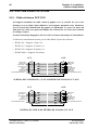
2.6.1 - Câble de liaison OCP CCU
La longueur maximale du câble reliant le pupitre avec le contrôle de voie est de
50 mètres avec un câble 5 paires blindés. Cette longueur maximale est de 100 mètres
si le fil 5 assurant l'alimentation du pupitre est quadruplé. La tresse de masse du
câble doit être reliée aux capots métalliques des connecteurs. Se référer aux schémas
de câblage ci-après.
La masse mécanique du pupitre doit être reliée à la masse mécanique de l'installation.
La liaison est normalement assurée par un câble blindé 5 paires de référence :
• BC041.001 - longueur 1 mètre, ou
• BC041.015 - longueur 15 mètres, ou
• BC041.050 - longueur 50 mètres, ou
• BC042100AA - longueur 100 mètres.
CCU
GROUND
GROUND
RETURN A
RETURN B
OUT B
OUT A
GROUND
GROUND
OCP POWER SUPPLY
OCP
1
1
6
6
2
2
7
7
3
3
8
8
4
4
9
9
5
5
GROUND
GROUND
OUT A
OUT B
RETURN B
RETURN A
GROUND
GROUND
OCP POWER SUPPLY
Tresse de masse du câble
SCHÉMA DES CÂBLES DE 1, 15 OU 50 MÈTRES DE LIAISON CCU OCP
CCU
OCP
1
GROUND
RETURN A
RETURN B
OUT B
OUT A
GROUND
OCP POWER SUPPLY
1
6
6
2
2
7
7
3
3
8
8
4
4
9
9
5
5
GROUND
OUT A
OUT B
RETURN B
RETURN A
GROUND
OCP POWER SUPPLY
Tresse de masse du câble
SCHÉMA DU CÂBLE 100 MÈTRES DE LIAISON CCU OCP
THOMSON EFP1685 / CCU1686
Manuel utilisateur
B1685902AC
Septembre 2000
Chapitre 2 - Installation
Pupitre d’exploitation
41
2.6.2 - Numérotation des pupitres, choix de la priorité
Un Contrôle de Voie peut être équipé dans sa configuration maximale de 3 pupitres OCP.
Si plusieurs pupitres sont connectés sur l'équipement, il est impératif que ces pupitres aient
des numéros et des priorités différents. Se référer au manuel de l' OCP.
2.6.3 - Adaptation d'impédance
Seul le pupitre le plus éloigné du contrôle de voie doit être fermé sur 150 Ω.
2.6.4 - Alimentation des pupitres
Si l’équipement est exploité avec un seul pupitre, utiliser la sortie "RCP POWER OUT"
(CCU1685) ou l’embase RCP (CCU1685/1686) du Contrôle de Voie pour alimenter le
pupitre. Si l’embase RCP est utilisé, se référer au paragraphe 2.6.1 - Câble de liaison OCP
CCU.
Dans le cas d’utilisation de plusieurs pupitres, utiliser une ou plusieurs unités PPU
(2 x 4 sorties "12 Volts") pour alimenter les pupitres.
Dans le cas de grande distance entre unité PPU et pupitre, il y a lieu d’augmenter les
tensions de sortie du PPU (par réglage interne) pour compenser les chutes de tension dans
le câble de liaison.
La valeur nécessaire au pupitre est égale à 12 V + 2 V - 1 V.
2.6.5 - Connection d’un pupitre en face avant du Contrôle de Voie
• Carte APCM version 0:
Connecter le pupitre sur l'embase située sur la face avant de la carte "APCM" du Contrôle
de Voie en veillant à placer l’inverseur "LOOP/150 Ω" sur la position 150 Ω.
NOTA : L'embase situé sur la face avant de la carte "APCM" ne délivre pas de 13 V
sur la broche 5.
• Carte APCM version 1:
Cette carte ne possède pas de connecteur en face avant.
B1685902AC
Septembre 2000
THOMSON EFP1685 / CCU1686
Manuel utilisateur
42
Chapitre 2 - Installation
Numérotation du contrôle de voie (utilisation avec un MCP)
2.7 - NUMÉROTATION DU CONTRÔLE DE VOIE (UTILISATION AVEC UN MCP)
Lorsque l'équipement est commandé par un système centralisé MCP, une adresse propre
doit lui être affectée. Cette adresse définit le numéro de caméra sur le MSP.
Il est impératif de donner une adresse différente aux Contrôles de Voie reliés à une
même unité MCP.
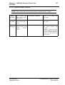
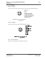
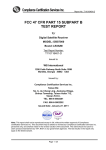
2.7.1 - Carte APCM version 0
L’affectation de cette adresse se fait au moyen de la roue codeuse RC140 située en
face avant de la carte APCM et des switchs 5 et 6 de S250 sur la carte APCM.
Le switch 7 de S250 indiquant la présence d'un MCP doit être positionné sur ON.
S250
ON AIR
1
2
STATUS
CAM BUSY
ON LINE
RCP
S250
MCP
8
J1
AUX
ON
CONTACT
VOLTAGE
1
ON AIR 1
RCP
E10
E11
CCU
R1
RC140
MCP
1
E12
CHAR WIDTH
NUMBER
E13
ON AIR 2
APCM
Roue codeuse RC140
Carte APCM version 0
Affectation des numéros :
• la roue codeuse permet la numérotation des CCUS de 1 à 15 (position 1 à 9 = caméras 1
à 9 et position A à F = caméras 10 à15, la position 0 étant interdite),
• le switch 5 en position ON et le switch 6 en position OFF ajoute 10 à la valeur de la roue
codeuse,
• le switch 6 en position ON et le switch 5 en position OFF ajoute 20 à la valeur de la roue
codeuse.
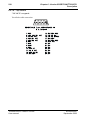
Récapitulatif des numéros de CCU en fonction de la roue codeuse RC140 et des
switchs 5 et 6 de S250 :
S250
Position roue codeuse
5
6
OFF
OFF
0
1
2
3
4
5
6
7
8
9
A
B
C
D
E
F
1
2
3
4
5
6
7
8
9
10
11
12
13
14
15
THOMSON EFP1685 / CCU1686
Manuel utilisateur
B1685902AC
Septembre 2000
Chapitre 2 - Installation
Numérotation du contrôle de voie (utilisation avec un MCP)
S250
43
Position roue codeuse
5
6
0
1
2
3
4
5
6
7
8
9
A
B
C
D
E
ON
OFF
10
11
12
13
14
15
16
17
18
19
20
21
22
23
24
OFF
ON
20
21
22
23
24
ON
ON
F
Position interdite
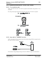
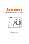
2.7.2 - Carte APCM version 1
L’affectation de cette adresse se fait au moyen des roues codeuses RC10 et RC1
situées en face avant de la carte APCM..
ON AIR
1
2
STATUS
CAM BUSY
ON LINE
RCP
MCP
MCP
NUMBER
Roue codeuse RC10
Roue codeuse RC1
APCM
Carte APCM version 1
Affectation des numéros (1 à 24) :
• la roue codeuse RC10 permet de numéroter le chiffre des dizaines. Sa position doit être
comprise entre 0 et 2.
• la roue codeuse RC1 permet de numéroter le chiffre des unités. Sa position doit être
entre le chiffre 0 et 9.
Exemple: Si le CCU est le n°14: RC10 = 1 et RC1 = 4.
B1685902AC
Septembre 2000
THOMSON EFP1685 / CCU1686
Manuel utilisateur
44
Chapitre 2 - Installation
Adaptation aux signalisations d’antenne principale et d’antenne secondaire
2.8 - ADAPTATION AUX SIGNALISATIONS D’ANTENNE
PRINCIPALE ET D’ANTENNE SECONDAIRE DANS LE
CONTRÔLE DE VOIE
Les commandes d’antenne principale "ON AIR 1" et d’antenne secondaire "ON AIR 2"
reçues par le Contrôle de Voie peuvent se présenter sous 2 formes différentes :
• une tension continue comprise entre + 12 Volts et + 48 Volts,
• une boucle fermée (contact).
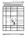
2.8.1 - Carte APCM version 0
Suivant le type de commande provenant du Mélangeur, placer les cavaliers E10, E11 (ON
AIR 1) et E12, E13 (ON AIR 2) sur les positions indiquées sur la figure suivante :
Adaptation ON AIR 1
Adaptation ON AIR 2
Commande
E10 - E11
Commande
E12 - E13
+ 12 Volts
Voltage
+ 12 Volts
Voltage
+ 24 Volts
Voltage
+ 24 Volts
Voltage
+ 48 Volts
Voltage
+ 48 Volts
Voltage
Boucle
Contact
Boucle
Contact
S250
8
J1
ON
CONTACT
VOLTAGE
1
ON AIR 1
E10
E11
RC140
R1
CHAR WIDTH
E12
E13
ON AIR 2
Carte"APCM" version 0
THOMSON EFP1685 / CCU1686
Manuel utilisateur
B1685902AC
Septembre 2000
Chapitre 2 - Installation
45
Adaptation aux signalisations d’antenne principale et d’antenne secondaire
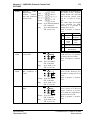
2.8.2 - Carte APCM version 1
Suivant le type de commande provenant du Mélangeur, placer les switchs S10, S11 (ON
AIR 1) et S12, S13 (ON AIR 2) sur les positions indiquées sur la figure suivante :
Adaptation ON AIR 1
Adaptation ON AIR 2
Commande
S10 - S11
Commande
S12 - S13
+ 12 Volts
Voltage
+ 12 Volts
Voltage
+ 24 Volts
Voltage
+ 24 Volts
Voltage
+ 48 Volts
Voltage
+ 48 Volts
Voltage
Boucle
Contact
Boucle
Contact
R300
PT11
Z400
PT18 PT19
C400 C402
PT10
S2
PT15
PT21
PT17
PT20
PT22
C B A
I
C401
Z360
PT16
I
CRL1
S1
I
I
Y30
15
8
I
I
J61
C300
10
I
Z410
I
I
I
34
I
Z320
J60
I
I
C320
C160
Z370
Z160
I
TB11
TB21
Z300
I
23
I
TB10
TB20
12
Z220
I
I
CRL4
Z200
C403
22
S250
CRL2
Z170
B1 A1
J70
Z230
9
S260
S10
S11
S12
C613
Z210
RC10
9
B3 A3
Z130
Z100
R620
R624
C130
9
20
C2
9
9
9
TB30
TB40
TB50
TB31
TB41
TB51
C612
9
J1
P1
9
9
R640
R644
9
C610
R110
R702
R703
R704
R705
R706
R707
R708
R709
Z110 C110
C611
S13
PT31
ORIGINE
PT1
PT5
PT12
PT41
PT13
PT4
PT40
PT14
PT23
30
L2
Y10
PT2 PT3
PT30
L610
RC1
PT32
S10 - S11
S12 - S13
Carte"APCM" version 1
B1685902AC
Septembre 2000
THOMSON EFP1685 / CCU1686
Manuel utilisateur
46
Chapitre 2 - Installation
Choix "avec ou sans caractères sur la vidéo de contrôle PM"
2.9 - CHOIX "AVEC OU SANS CARACTÈRES SUR LA VIDÉO
DE CONTRÔLE PM"
NOTA : Deux types de carte "VIDEO" équipent les CCU1685 et 1686.
La version 1 est équipée de la fonction "PIP" (picture in picture) utilisée avec les caméras
de studio. Elle est identifiable par la présence d'un quartz sur sa face composants.
Différents affichages renseignant l'exploitant sur les valeurs des réglages d'exploitations et
les états de la caméra ou du Contrôle de voie peuvent être incrustés sur la vidéo PM (se
référer au chapitre EXPLOITATION).
Leur présence dépend du commutateur S1 (CHR : ON/OFF) situé sur la carte VIDEO.
Placer ce commutateur sur la position convenable.
PIX
CHR
ON
S1
OFF
Face
avant
"VIDEO"/"VIDEO PIP" PCB (CCU)
THOMSON EFP1685 / CCU1686
Manuel utilisateur
B1685902AC
Septembre 2000
Chapitre 2 - Installation
Sélection de la vidéo numérique en test
47
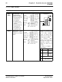
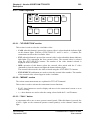
2.10 -SÉLECTION DE LA VIDÉO NUMÉRIQUE EN TEST
NOTA : En Exploitation, RC1 doit impérativement être positionné sur la position F.
RC1
Face
avant
RC3
RC4
"ENC 4.2.2" PCB (CCU)
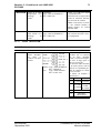
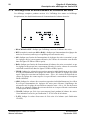
La carte "ENCODER 4.2.2" est équipé d'un commutateur RC1 permettant :
• de sélectionner la source présente sur la sortie numérique série,
ou
• d'effectuer certaines modifications du signal présent sur la sortie numérique série.
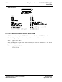
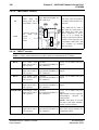
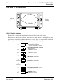
2.10.1 - Signal disponible sur les sorties numériques en fonction des
commandes "BARS" et "PM" du pupitre
2.10.1.1 - Le commutateur RC1 est en position exploitation
Le commutateur RC1 est sur la position F
Le signal disponible dépend :
• du signal sélectionné (image, dent de scie ou mire de barres, touche BARS),
• de la sélection de la vidéo PM (SETTING CCU, touche SETTING).
1er cas : le pupitre est sur image et quelque soit la position "PM": SORTIE NUMÉRIQUE = VIDÉO CAMÉRA.
2ème cas : le pupitre est sur "MIRE DE BARRES" et si "PM" est différent de "ENC":
SORTIE NUMÉRIQUE = MIRE DE BARRES CAMÉRA.
3ème cas : le pupitre est sur "MIRE DE BARRES" et si "PM" est égal à "ENC":
SORTIE NUMÉRIQUE = MIRE DE BARRES 100% SYNTHÉTIQUE (généré par le
codeur numérique).
4ème cas : le pupitre est sur "TEST" et si "PM" est différent de "ENC": SORTIE
NUMÉRIQUE = SIGNAL TEST CAMÉRA.
5ème cas : le pupitre est sur "TEST" et si "PM" est égal à "ENC": SORTIE NUMÉRIQUE = DENT DE SCIE TEST NUMÉRIQUE (généré par le codeur numérique).
B1685902AC
Septembre 2000
THOMSON EFP1685 / CCU1686
Manuel utilisateur
48
Chapitre 2 - Installation
Sélection de la vidéo numérique en test
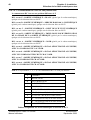
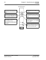
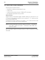
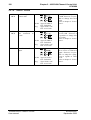
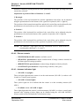
2.10.1.2 - Le commutateur RC1 est sur une position test
Le commutateur RC1 est sur une position différente de F
RC1 est sur E : SORTIE NUMÉRIQUE = BLANC (généré par le codeur numérique),
quelque soit la sélection faite sur l'OCP.
RC1 est sur D : SORTIE NUMÉRIQUE = MIRE DE BARS 100 % SYNTHÉTIQUE
(généré par le codeur numérique), quelque soit la sélection faite sur l'OCP.
RC1 est sur C : SORTIE NUMÉRIQUE = DENT DE SCIE TEST NUMÉRIQUE
(généré par le codeur numérique), quelque soit la sélection faite sur l'OCP.
RC1 est sur B : SORTIE NUMÉRIQUE = IMPULSIONS POUR VÉRIFICATION
DE LA PHASE DE LA SORTIE NUMÉRIQUE (généré par le codeur numérique),
quelque soit la sélection faite sur l'OCP.
RC1 est sur A : SORTIE NUMÉRIQUE = NOIR (généré par le codeur numérique),
quelque soit la sélection faite sur l'OCP.
RC1 est sur 9 : SORTIE NUMÉRIQUE = SIGNAL SÉLECTIONNÉ AU PUPITRE,
AVEC LA COMPOSANTE Y AU NOIR.
RC1 est sur 8 : SORTIE NUMÉRIQUE = SIGNAL SÉLECTIONNÉ AU PUPITRE,
AVEC LES COMPOSANTES CR ET CB AU NOIR.
RC1 est sur 7 : SORTIE NUMÉRIQUE = SIGNAL SÉLECTIONNÉ AU PUPITRE,
AVEC LA COMPOSANTE CR AU NOIR.
RC1 est sur 6 : SORTIE NUMÉRIQUE = SIGNAL SÉLECTIONNÉ AU PUPITRE,
AVEC LA COMPOSANTE CB AU NOIR.
NOTA : Les positions 0, 1, 2, 3, 4, 5 du commutateur RC1 ne sont pas utilisées.
F
CAMERA
E
WHITE NUM.
D
100 % BARS NUM.
C
SAW TEST NUM.
B
PULSE NUM.
A
NOIR GENERAL NUM.
9
CR/CB (Noir sur Y) de la vidéo sélectée
8
Y (Noir sur CR/CB) de la vidéo sélectée
7
Y + CB (Noir sur CR) de la vidéo sélectée
6
Y + CR (Noir sur CB) de la vidéo sélectée
0à5
NON UTILISÉES
Tableau récapitulatif des sorties numériques en fonction de RCI
THOMSON EFP1685 / CCU1686
Manuel utilisateur
B1685902AC
Septembre 2000
Chapitre 2 - Installation
Gestion du CALL
49
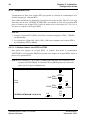
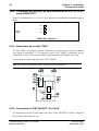
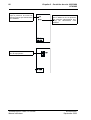
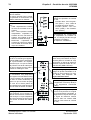
2.11 -GESTION DU CALL
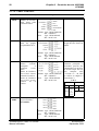
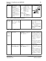
L'information "CALL" en provenance de la caméra peut être ou non mémorisée en fonction du switch 4 de S250 situé sur la carte APCM.
Switch en position ON, CALL mémorisé :
• au relâchement de la commande CALL de la caméra tous les voyants CALL de
l'équipement restent actifs, ainsi que l'indication CALL CAM CCU OUT (broche 5 de
la prise ON AIR en face arrière du CCU).
Pour éteindre le voyant CALL d'un pupitre :
• appuyer sur la touche CALL de ce pupitre.
Pour éteindre toutes les indications CALL de l'équipement, effectuer une des actions
suivantes :
• appuyer simultanément sur les touches PRESET et CALL du pupitre,
• appuyer sur le switch CALL situé en face avant de la carte STEREO INTERCOM du
contrôle de voie,
• envoyer un CALL externe sur la prise ON AIR en face arrière du contrôle de voie
(broche 6 CALL CCU CAM IN).
Switch en position OFF, CALL non mémorisé :
• au relâchement de la commande CALL de la caméra tous les voyants CALL de
l'équipement se désactivent, ainsi que l'indication CALL CAM CCU OUT (broche 5 de
la prise ON AIR en face arrière du CCU).
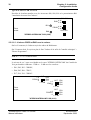
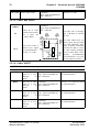
2.12 -MÉMORISATION DU MASTER BLACK EN SCENE FILE
Le MASTER BLACK peut être ou non mémorisée en SCENE FILE en fonction du
switch 3 de S250 situé sur la carte APCM.
Switch en position OFF :
MASTER BLACK mémorisé dans les SCENE FILE.
Switch en position ON :
MASTER BLACK non mémorisé dans les SCENE FILE.
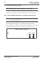
2.13 -VITESSE DE TRANSMISSION CCU - PUPITRE
Pour certaines applications spécifiques, la vitesse de transmission peut être abaissée à
9600 bauds (switch 1 de S250). La vitesse standard étant 38400 bauds.
Switch en position OFF :
Vitesse : 38400 bauds (cas standard).
B1685902AC
Septembre 2000
THOMSON EFP1685 / CCU1686
Manuel utilisateur
50
Chapitre 2 - Installation
Choix du standard 525 ou 625 lignes
Switch en position ON :
Vitesse : 9600 bauds.
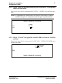
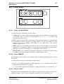
2.14 -CHOIX DU STANDARD 525 OU 625 LIGNES
Switch 2 de S250:
Switch en position OFF :
Standard 625 lignes.
Switch en position ON :
Standard 525 lignes
THOMSON EFP1685 / CCU1686
Manuel utilisateur
B1685902AC
Septembre 2000
Chapitre 2 - Installation
Implantation des cartes APCM version 0 et 1
51
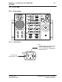
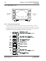
2.15 -IMPLANTATION DES CARTES APCM VERSION 0 ET 1
S 250
S250
8
J1
ON
CONTACT
VOLTAGE
1
ON AIR 1
E10
E11
RC140
R1
E12
CHAR WIDTH
E13
ON AIR 2
Carte "APCM" version 0
S250
C400 C402
R300
Z400
PT18 PT19
PT22
C B A
C401
I
I
J61
C300
8
Z170
S260
R620
R624
20
S11
R640
R644
S10
S12
C2
B1 A1
J70
Z230
9
C613
Z210
9
B3 A3
Z130
Z100
9
TB30
TB40
TB50
TB31
TB41
TB51
C612
C130
9
P1
9
C610
R110
R702
R703
R704
R705
R706
R707
R708
R709
Z110 C110
9
RC10
10
I
I
Z410
I
Z320
I
I
I
34
C403
C160
Z370
15
J60
Z300
C320
23
Z160
I
I
TB11
TB21
12
Z220
9
9
PT20
I
9
9
PT21
PT17
22
Z200
1
J1
PT16
PT15
I
8
I
S250
I
TB10
TB20
PT11
Z360
I
ON
CRL2
CRL4
PT10
S2
I
CRL1
I
I
Y30
S1
C611
S13
ORIGINE
PT31
PT12
PT1
PT5
PT41
PT13
PT4
PT40
PT14
PT23
30
L2
Y10
PT2 PT3
PT30
L610
RC1
PT32
Carte "APCM" version 1
B1685902AC
Septembre 2000
THOMSON EFP1685 / CCU1686
Manuel utilisateur
52
THOMSON EFP1685 / CCU1686
Manuel utilisateur
Chapitre 2 - Installation
Implantation des cartes APCM version 0 et 1
B1685902AC
Septembre 2000
Chapitre 3 - Contrôles de voie 1685/1686
53
Chapitre 3
Contrôles de voie 1685/1686
3.1 - CCU1685 ........................................................................ 55
3.1.1 - Face arrière ......................................................................................... 55
3.1.1.1 - Cadre "ALIMENTATION" .................................................................
3.1.1.2 - Cadre "CONTROL" ..........................................................................
3.1.1.3 - Cadre "DIGITAL VIDEO" .................................................................
3.1.1.4 - Cadre "ANALOG I/O".......................................................................
3.1.1.5 - Cadre "AUDIO" ................................................................................
55
56
57
58
60
3.1.2 - Face avant ........................................................................................... 62
3.2 - CCU1686 ........................................................................ 67
3.2.1 - Face arrière ......................................................................................... 67
3.2.1.1 - Alimentation .....................................................................................
3.2.1.2 - Cadre "CONTROL" ..........................................................................
3.2.1.3 - Cadre "SERIAL DIGITAL OUTPUT" ................................................
3.2.1.4 - Cadre "VIDEO OUTPUT".................................................................
3.2.1.5 - Cadre "MIX VIDEO" .........................................................................
3.2.1.6 - Cadre "INPUT".................................................................................
3.2.1.7 - Cadre "INTERCOM" ........................................................................
3.2.1.8 - Cadre "AUDIO" ................................................................................
67
68
69
69
70
70
71
72
3.2.2 - Face avant ........................................................................................... 73
B1685902AC
Septembre 2000
THOMSON EFP1685 / CCU1686
Manuel utilisateur
54
THOMSON EFP1685 / CCU1686
Manuel utilisateur
Chapitre 3 - Contrôles de voie 1685/1686
B1685902AC
Septembre 2000
Chapitre 3 - Contrôles de voie 1685/1686
CCU1685
55
3.1 - CCU1685
3.1.1 - Face arrière
CONTROL
MCP
110/220/240 V
RCP POWER
+12 V OUT
DIGITAL VIDEO
RET 3
RCP
RET 1
ON AIR
PROMPTER
AUX.PORT
GEN - LOCK
RET 4
ANALOG I / O
RET 2
OUT
MIX VIDEO
ENC. OUT
VIDEO OUT
2
1
R
R-Y
AUDIO
MIC REM
MIC 2 OUT
INTERCOM
PROD
IN
G
Y
SYNC. OUT
MIC 1 OUT
SERIAL OUTPUT
PGM IN
PIX
ENG
B
B-Y
AC
3.1.1.1 - Cadre "ALIMENTATION"
110/220/240 V
RCP POWER
+12 V OUT
Prise d’entrée
d’alimentation secteur
AC
RCP
POWER
+ 12 V OUT
Embase d’alimentation
du pupitre.
Embase Type : XLR-4-31
Réf : 91.538.047
Prise
Type : XLR-4-12C
Réf : 91.647.565
B1685902AC
Septembre 2000
THOMSON EFP1685 / CCU1686
Manuel utilisateur
56
Chapitre 3 - Contrôles de voie 1685/1686
CCU1685
3.1.1.2 - Cadre "CONTROL"
NOTA : Les embases sont représentées côté câblage.
MCP
Embase de raccordement d’une unité
centralisée MCP.
Embase Type : HE501F09KS3E
Réf : T9000678
Prise
Type : HE501N09AS
Réf : 99.027.194
RCP
Embase de raccordement du pupitre
d’exploitation OCP.
Seul le pupitre le plus
éloigné doit être fermé sur
150 Ω.
Embase Type : HE501F09KS3E
Réf : T9000678
Prise
Type : HE501N09AS
Réf : 99.027.194
ON AIR
Entrées des signalisations
"Antenne
principale"
et
"Antenne
secondaire".
Entrée de l'information "CALL" à destination de la caméra.
Sortie de l'information "CALL" en provenance
de
la
caméra.
Embase Type : HE501F09KS3E
Réf : T9000678
Prise
Type : HE501N09AS
Réf : 99.027.194
Les
commutations
d’antenne principale et
secondaire peuvent être
commandées par une boucle fermée ou par une tension
comprise
entre
+ 12 Volts et + 48 Volts
(se référer au chapitre 2
"Installation").
CALL
Call IN
ON
0V
Call OUT
ON
0V
OPEN OFF + 5 V
OFF or
4Và
12 V
AUX.
PORT
Embase prévue pour
un port auxiliaire.
Non utilisée.
Embase Type : HE501F09KS3E
Réf : T9000678
Prise
Type : HE501N09AS
Réf : 99.027.194
THOMSON EFP1685 / CCU1686
Manuel utilisateur
B1685902AC
Septembre 2000
Chapitre 3 - Contrôles de voie 1685/1686
CCU1685
57
3.1.1.3 - Cadre "DIGITAL VIDEO"
NOTA : Les vidéos avec passage en sonde doivent être impérativement fermées sur 75 Ω.
RET3
IN OUT
Entrée de la vidéo
retour N° 3 avec
"Passage en sonde".
2 Embases Réf : T6000050
Niveau : 1 V/75 Ω, avec
signal de synchronisation.
RET4
IN OUT
Entrée de la vidéo
retour N° 4 avec
"Passage en sonde".
2 Embases Réf : T6000050
Niveau : 1 V/75 Ω, avec
signal de synchronisation.
SERIAL
OUTPUT
4 sorties vidéo numérique série 270 Mbits
(avec option codeur
numérique).
4 Embases Réf : T6000047
Il est recommandé de fermer
les sorties non utilisées sur
75 Ω.
NOTA : En position mire de
barres et dent de scie test synthétiques, le numéro de CCU
s'affiche en bas à gauche de
l'image numérique.
B1685902AC
Septembre 2000
THOMSON EFP1685 / CCU1686
Manuel utilisateur
58
Chapitre 3 - Contrôles de voie 1685/1686
CCU1685
3.1.1.4 - Cadre "ANALOG I/O"
NOTA : Les vidéos avec passage en sonde doivent être impérativement fermées sur 75 Ω.
RET1
IN OUT
Entrée de la vidéo 2 Embases
retour N° 1 avec "Pas- Type : BNC50-EFDPEI-Y3
sage en sonde".
Réf : T9001518
Niveau : 1 V/75 Ω, avec
signal de synchronisation.
RET2
IN OUT
Entrée de la vidéo 2 Embases
retour N° 2 avec "Pas- Type : BNC50-EFDPEI-Y3
sage en sonde".
Réf : T9001518
Niveau : 1 V/75 Ω, avec
signal de synchronisation.
PROMPTER Entrée de la vidéo télé- 2 Embases
IN OUT
prompter avec "Pas- Type : BNC50-EFDPEI-Y3
sage en sonde".
Réf : T9001518
Niveau : 1 V/75 Ω, avec
signal de synchronisation.
Entrée/Sortie d’un signal
vidéo destiné au moniteur
télésouffleur de la tête de
caméra.
NOTA : Cette entrée est
réservée aux caméras lourdes et caméras légères en
version "SPORTCAM".
MIX VIDEO
IN
2 Embases
Type : BNC50-EFDPEI-Y3
Entrée de la vidéo desRéf : T9001518
tinée à être mélangée à
l'une des 4 vidéos
FROM CAM
FROM CAM
"RET".
SELECT
INFO
RET VIDEO
MIX VIDEO
FROM
REAR PANEL
RET 1
RET VIDEO
or
RET 2
MIX VIDEO
TO CAM
RET 3
OUT
Sortie de la vidéo Y
caméra (avec signal de
synchronisation).
Niveau :1 V/75 Ω.
RET 4
VIDEO
MIX IN
FROM CAM
VIDEO
R
G
Y
MIX OUT
B
"VIDEO" PCB
La vidéo "IN" est chargée
par 75 Ω dans le contrôle de
voie.
La vidéo "MIX OUT" est
prévue pour être raccordée à
la vidéo "MIX IN", après
mise en phase éventuelle,
afin d'avoir dans le viseur la
vidéo caméra mélangée avec
la vidéo "RET" sélectionnée
(Commutateurs
"EXT
SELECT" et V/F sur le côté
gauche du CA85).
GEN-LOCK Entrée de la vidéo 2 Embases
IN OUT
GEN LOCK avec Type : BNC50-EFDPEI-Y3
"Passage en sonde".
Réf : T9001518
Entrée/Sortie d’un signal
vidéo codé extérieur destiné
à asservir l’équipement.
SYNC. OUT Sortie d’un signal de Embase
synchronisation.
Type : BNC50-EFDPEI-Y3
Réf : T9001518
Signal mélangé de polarité
négative et d’amplitude
2 V/75 Ω pour synchroniser
un moniteur RGB ou un
appareil de mesure.
THOMSON EFP1685 / CCU1686
Manuel utilisateur
B1685902AC
Septembre 2000
Chapitre 3 - Contrôles de voie 1685/1686
CCU1685
PIX
ENC. OUT
59
Sortie vidéo avec syn- Embase
chro destinée au moni- Type : BNC50-EFDPEI-Y3
teur de contrôle PM.
Réf : T9001518
Niveau 1 V/75 Ω.
La sélection de la vidéo de
sortie se fait à partir du pupitre.
Les réglages d’exploitation
peuvent être incrustés dans
la vidéo de contrôle (se référer au chapitre 2 "Installation" et au chapitre 5 "
Exploitation").
Sorties vidéo codée
Niveau 1 V/75 Ω.
3 Embases
Type : BNC50-EFDPEI-Y3
Réf : T9001518
VIDEO OUT
1
R (R-Y)
G (Y)
B (B-Y)
Sorties vidéo.
3 Embases
Type : BNC50-EFDPEI-Y3
Réf : T9001518
Les sorties peuvent être configurées en vidéos R, G, B ou
composantes Y, R-Y, B-Y.
Des signaux de synchronisation peuvent être rajoutés sur
la vidéo verte (commun à
VIDÉO OUT 2). Se référer
au chapitre 2 "Installation".
Niveau 700 mV/75 Ω sauf
1 V/75 Ω sur la vidéo verte
si le signal de synchronisation est présent.
VIDEO OUT
2
R (R-Y)
G (Y)
B (B-Y)
Sorties vidéo.
3 Embases
Type : BNC50-EFDPEI-Y3
Réf : T9001518
Les sorties peuvent être configurées en vidéos R, G, B ou
composantes Y, R-Y, B-Y.
Des signaux de synchronisation peuvent être rajoutés sur
la vidéo verte (commun à
VIDÉO OUT 1). Se référer
au chapitre 2 "Installation".
Niveau 700 mV/75 Ω sauf
1 V/75 Ω sur la vidéo verte
si le signal de synchronisation est présent.
B1685902AC
Septembre 2000
THOMSON EFP1685 / CCU1686
Manuel utilisateur
60
Chapitre 3 - Contrôles de voie 1685/1686
CCU1685
3.1.1.5 - Cadre "AUDIO"
NOTA : Les embases sont représentées côté câblage.
MIC.
REM
PROD
Raccordement
de
2 potentiomètres
(10 kΩ à 50 kΩ) de :
• télécommande de
sensibilité du
microphone
d’ambiance raccordé à la tête de
caméra,
• télécommande de
sensibilité du
microphone raccordé au CA85.
Connection
Tel. MIC 1
GND
6
Embase Type : HE501F09KS3E
Réf : T9000678
Prise
Type : HE501N09AS
Réf : 99.027.194
Entrée/Sortie Audio
interphonie entre le
Cadreur et le Réalisateur.
Embase Type : HE501F09KS3E
Réf : T9000678
Prise
Type : HE501N09AS
Réf : 99.027.194
Tel. MIC 2+5V
GND
7
8
9
1
2 +5V
3
4
5
Suivant la position des
cavaliers qui se trouvent
sur la carte "INTERCOM", la liaison interphonie avec la régie peut
se faire sur 2 ou 4 fils.
Les
niveaux
audio
d’entrée et de sortie prévus sont de 0 dB. Il est
cependant possible de
changer la valeur de ces
niveaux.
Se référer au chapitre 2
"Installation".
N°
4 FILS
2 FILS
Vers salle
Non
3 - 8 de contrôle connectés
De la salle
2 - 7 de contrôle
THOMSON EFP1685 / CCU1686
Manuel utilisateur
De et vers
la salle
de contrôle
4
Canal RTS Réalisateur
5
Canal RTS
salle technique
B1685902AC
Septembre 2000
Chapitre 3 - Contrôles de voie 1685/1686
CCU1685
ENG
61
Entrée/Sortie Audio
interphonie entre le
Cadreur et Salle de
contrôle technique.
Embase Type : HE501F09KS3E
Réf : T9000678
Prise
Type : HE501N09AS
Réf : 99.027.194
Suivant la position des
cavaliers qui se trouvent
sur la carte "INTERCOM", la liaison interphonie avec la régie peut
se faire sur 2 ou 4 fils.
Les
niveaux
audio
d’entrée et de sortie prévus sont de 0 dB. Il est
cependant possible de
changer la valeur de ces
niveaux.
Se référer au chapitre 2
"Installation".
N°
4 FILS
2 FILS
Non
Vers salle
3 - 8 de contrôle connectés
De la salle
2 - 7 de contrôle
MIC 1
OUT
Sortie Audio provenant
du
Micro
Caméra.
GND
1
(X)
2
(Y)
3
Embase Type : NC3MK-V
Réf : T1002568
Prise
Type : XLR-3-11C
Réf : 91.355.160
MIC 2
OUT
Sortie Audio provenant du Micro connecté sur le CA85.
GND
1
(X)
2
(Y)
3
Embase Type : NC3MK-V
Réf : T1002568
Prise
Type : XLR-3-11C
Réf : 91.355.160
PGM IN
Entrée du Son PROGRAMME
GND
1
(X)
2
(Y)
3
Embase Type : NC3FK-V
Réf : T1002569
Prise
Type : XLR-3-12C
Réf : 91.355.162
B1685902AC
Septembre 2000
De et vers
la salle
de contrôle
4
Canal RTS Réalisateur
5
Canal RTS
salle technique
Le niveau audio de sortie
prévu est de 0 dB. Il est
cependant possible de
changer la valeur de ce
niveau.
Se référer au chapitre 2
"Installation".
Le niveau audio de sortie
prévu est de 0 dB. Il est
cependant possible de
changer la valeur de ce
niveau.
Se référer au chapitre 2
"Installation".
L’équipement est normalement réglé pour recevoir
un signal de niveau 0 dB.
Il est cependant possible
d’adapter l’équipement à
des signaux de niveau différent.
Se référer au chapitre 2
"Installation".
THOMSON EFP1685 / CCU1686
Manuel utilisateur
62
Chapitre 3 - Contrôles de voie 1685/1686
CCU1685
3.1.2 - Face avant
ON AIR
1
SHORT CABLE
2
GEN
LOCK
PRG
SYNC. OUT
SYNC. FAIL.
CAM
ENG
RETURN
VIDEO IN
+12V
-30V
flH
ON
I
STATUS
REMOTE
BUSY
FAIL
OVERLOAD
CABLE OPEN
MAINS
O
ON LINE
CAM
RCP
MCP
flSC
G OUT
I min
PROD
R OUT
CAM.HEAD
LOW VOLT
+12V
+300V
AUX
0
CALL
RCP
+230VDC
B OUT
MCP
CAM
flSC/H
OFF
TRIAX
STEREO
INTERCOM
CCU
CHROMA
LEVEL
ENG
CAM
VIDEO
1
NUMBER
PAL
ENCODER
4-2-2
ENCODER
APCM
CAMERA
POWER
CCU
POWER
MAINS
RECTIFIER
Point Test du signal de synchronisation extrait de la vidéo V (Vcc =
9 V Zout = 300 Ω).
Indication d’un câble court de
liaison entre la tête de caméra et le
contrôle de voie.
Avec un câble long (> 300 m
type B), la vidéo du téléprompter
n’est plus disponible sur la tête de
caméra.
SHORT CABLE
SYNC. OUT
RETURN
VIDEO IN
SYNC. FAIL.
R OUT
Point Test du signal vidéo extérieur
injecté à l’arrière du contrôle de
voie (Zout = 75 Ω).
G OUT
Indication d’absence du signal de
synchronisation extrait de la
voie V.
Cela peut être dû :
• à la mise hors tension de la tête
de caméra,
• au débranchement du câble de
liaison Tête de caméra ↔ Contrôle de voie, etc...
B OUT
Points Test des signaux vidéo R, V,
B démodulés sans synchro
(Vcc = 0,7 V/75 Ω)
Point Test de masse
TRIAX
Le voyant signale un appel provenant du Cadreur.
Le bouton poussoir CALL permet
à l’Opérateur du Contrôle de voie
d’attirer l’attention du Cadreur.
Lorsque cet inverseur est en position :
• CAM : l’Opérateur du Contrôle
de Voie est en liaison avec le
Cadreur,
• OFF : c’est la position normale
d’exploitation. L’opérateur du
Contrôle de Voie est isolé du
Cadreur, de la Régie et de la
Salle de Contrôle technique.
• ENG-CAM : l’Opérateur du
Contrôle de Voie est en liaison
avec la Salle de Contrôle technique et le Cadreur.
THOMSON EFP1685 / CCU1686
Manuel utilisateur
PRG
ENG
CAM
PROD
CALL
CAM
OFF
ENG
CAM
STEREO
INTERCOM
Réglage des niveaux d’écoute du
casque de l’Opérateur du contrôle
de voie.
• Ecouteur droit : Son "Programme" (PRG ) + Son, "Salle de
Contrôle technique" (ENG).
• Ecouteur gauche : Son "Cadreur" (CAM) + Son "Réalisateur" (PROD).
Raccordement du casque-micro
de l’Opérateur du Contrôle de
voie. Le casque peut être de type
dynamique
ou
statique
(cf
chapitre 2 "Installation").
B1685902AC
Septembre 2000
Chapitre 3 - Contrôles de voie 1685/1686
CCU1685
Ce réglage øH - phase horizontale
- avance ou retarde (par rapport à
l'entrée GEN LOCK) le générateur
de synchronisation de l’équipement de façon à ce que la chaîne
de prise de vues ait la même phase que les autres sources vidéo à
l’entrée du mélangeur vidéo.
GEN
LOCK
REMOTE
ØH
Ø SC
Ce réglage øSc (réglage continu et
commutation 0/Π) déphase (par
rapport à l'entrée GEN LOCK) la
sous-porteuse de l’équipement (en
PAL ou NTSC seulement) de façon
à ce que la chaîne de prise de vues
ait la même phase de sous-porteuse que celle des autres sources vidéo à l’entrée du mélangeur vidéo.
63
¸
0
19H
V.BLK
2OH
Ce voyant vert signale que le générateur de synchronisation de l’équipement (dans le contrôle de voie)
est asservi au signal de référence
extérieur injecté à l’arrière du contrôle de voie (GEN LOCK IN).
Ce voyant rouge signale que les réglages de phase horizontale et de
phase de sous-porteuse (en PAL
ou NTSC) sont déportés. Ce
voyant doit être éteint.
21H
H.BLK
Ø SC/H
CHROMA
En NTSC, réglage de la largeur de
la suppression verticale (V.BLK) et
de la suppression horizontale
(H.BLK)
LEVEL
Ce réglage ajuste le niveau de la
sous porteuse sur les sorties codées en face arrière du contrôle de
voie de façon a ce que l'amplitude
de la sous porteuse du signal codé
soit correct à l'entrée du mélangeur.
PAL
ENCODER
NTSC
ENCODER
Ce réglage ø Sc/H ajuste la phase
entre la sous-porteuse et le signal
de synchronisation horizontale, si
l'équipement n'est pas asservi par
un signal de référence externe
(aucune vidéo sur l'entrée GEN
LOCK en face arrière du contrôle
de voie).
APCM Version 0
Ce voyant rouge signale que
l’équipement est sur antenne principale.
Ce voyant rouge, normalement
éteint, signale un défaut de transmission de télécommande entre
voie et caméra ou caméra et voie.
Ce voyant vert est allumé lorsqu’un pupitre au moins est raccordé au Contrôle de Voie.
Son clignotement indique que plusieurs pupitres ont la même adresse (conflit).
ON AIR
1
2
STATUS
CAM BUSY
ON LINE
RCP MCP
AUX
Embase de raccordement d’un pupitre de télécommandes (prévue
pour les opérations de maintenance).
B1685902AC
Septembre 2000
Le clignotement de ce voyant jaune témoigne du dialogue entre le
Contrôle de Voie et le(s) pupitre(s).
Ce voyant vert est allumé lorsque
le Contrôle de Voie est raccordé
comme tributaire, à un pupitre
CCP ou MCP.
RCP
MCP
CCU
Ce voyant jaune signale que
l’équipement est sur antenne secondaire.
1
NUMBER
APCM
Roue codeuse permettant de définir le numéro de CCU vue et affiché par le système centralisé et le
moniteur de contrôle PM.
THOMSON EFP1685 / CCU1686
Manuel utilisateur
64
Chapitre 3 - Contrôles de voie 1685/1686
CCU1685
APCM Version 1
Ce voyant rouge signale que
l’équipement est sur antenne principale.
ON AIR
1
2
Ce voyant jaune signale que
l’équipement est sur antenne secondaire.
STATUS
Ce voyant rouge, normalement
éteint, signale un défaut de transmission de télécommande entre
voie et caméra ou caméra et voie.
Ce voyant vert est allumé lorsqu’un pupitre au moins est raccordé au Contrôle de Voie.
Son clignotement indique que plusieurs pupitres ont la même adresse (conflit).
CAM BUSY
ON LINE
RCP
MCP
Le clignotement de ce voyant jaune témoigne du dialogue entre le
Contrôle de Voie et le(s) pupitre(s).
Ce voyant vert est allumé lorsque
le Contrôle de Voie est raccordé
comme tributaire, à un pupitre
CCP ou MCP.
MCP
NUMBER
Roues codeuses permettant de
définir le numéro de CCU vue et
affiché par le système centralisé et
le moniteur de contrôle PM.
APCM
THOMSON EFP1685 / CCU1686
Manuel utilisateur
B1685902AC
Septembre 2000
Chapitre 3 - Contrôles de voie 1685/1686
CCU1685
65
Ce voyant normalement allumé signale la présence de la tension
-30 V d’alimentation de secours de
l’interphonie, lorsque l’inverseur
POWER ON/OFF du CA85 est sur
OFF. La présence de cette tension
est indispensable pour le démarrage de l'équipement.
Ce voyant normalement allumé signale la présence de la tension
12 V qui alimente le circuit de
commande du convertisseur CAMERA POWER. Cette tension
provient du circuit CCU POWER.
Ce voyant normalement éteint signale une surconsommation anormale de la tête de caméra (ex :
court-circuit,...).
Ce voyant normalement éteint signale que le câble de liaison Caméra-contrôle de voie n’est pas
raccordé.
12V
- 30V
OVERLOAD
CABLE OPEN
I min
CAM. HEAD
LOW VOLT
Ce voyant normalement éteint indique une consommation électrique de la caméra anormalement
faible.
Ce voyant normalement éteint signale une valeur insuffisante de la
tension d’alimentation + 12 V ou 12 V du circuit de commande du
convertisseur CAMERA POWER
(V12V < 10 V ou V-12V > -2 V).
Ce voyant normalement allumé signale que la tête de caméra est
alimentée par le + 230 V.
B1685902AC
Septembre 2000
+12V
+300V
230 Vdc
CAMERA
POWER
L’allumage de ce voyant normalement éteint signale que l’inverseur
POWER ON/OFF de la tête de caméra est sur OFF. Il s’allume aussi
lorsqu’on raccorde par mégarde
une tête de caméra qui n’a pas été
prévue pour fonctionner avec le
Contrôle de Voie : le convertisseur
CAMERA POWER + 230 VDC est
alors bloqué.
Ce voyant normalement éteint signale une valeur insuffisante de la
tension d’alimentation "300V" du
convertisseur CAMERA POWER
issue de la carte MAINS RECTIFIER (V300 < 220 VDC).
THOMSON EFP1685 / CCU1686
Manuel utilisateur
66
Ce voyant normalement allumé indique la présence de toutes les
tensions fournies par l'alimentation
CCU POWER.
Chapitre 3 - Contrôles de voie 1685/1686
CCU1685
Ce voyant normalement éteint indique un défaut sur une ou plusieurs
des tensions d'alimentation fournie(s) par l'alimentation CCU
POWER.
ON
FAIL
CCU
POWER
Interrupteur de mise en/hors tension de l’équipement.
I
MAINS
0
MAINS
RECTIFIER
THOMSON EFP1685 / CCU1686
Manuel utilisateur
B1685902AC
Septembre 2000
Chapitre 3 - Contrôles de voie 1685/1686
CCU1686
67
3.2 - CCU1686
3.2.1 - Face arrière
VIDEO OUTPUT
INTERCOM
PGM IN
PIX
N
PRODUCER
R
AUDIO
R-Y
MIC 1 OUT
1
MIC 2 OUT
ENGINER
G
Y
ENC. OUT
MIX VIDEO
OUT
B
B-Y
I
2
IN
RET 3
RET 4
RET 1
RET 2
PROMPTER
GEN LOCK
N
P
U
SERIAL DIGITAL OUTPUT
1
T
2
C
O
N
RCP
MIC REM
MCP
ON AIR
T
3
R
4
O
L
3.2.1.1 - Alimentation
Fusible :
• T 2,5 A pour une alimentation
secteur de 220 V à 240 V,
• T 4 A pour une alimentation
secteur de 110 V.
N
Prise d’entrée
d’alimentation secteur
B1685902AC
Septembre 2000
THOMSON EFP1685 / CCU1686
Manuel utilisateur
68
Chapitre 3 - Contrôles de voie 1685/1686
CCU1686
3.2.1.2 - Cadre "CONTROL"
NOTA : Les embases sont représentées côté câblage.
MCP
Embase de raccordement d’une unité centralisée MCP.
Embase Type :
HE501F09KS3E
Réf : T9000678
Prise
Type : HE501N09AS
Réf : 99.027.194
RCP
Embase de raccordement du (des) pupitre(s)
d’exploitation
OCP.
Seul le pupitre le plus
éloigné doit être fermé sur
150 Ω.
Embase Type :
HE501F09KS3E
Réf : T9000678
Prise
Type : HE501N09AS
Réf : 99.027.194
ON AIR
Entrées des signalisations "Antenne principale"
et
"Antenne
secondaire".
Entrée de l'information
"CALL" à destination
de la caméra.
Embase Type :
Sortie de l'information HE501F09KS3E
"CALL" en provenance
Réf : T9000678
de la caméra.
Prise
Type : HE501N09AS
Réf : 99.027.194
Les
commutations
d’antenne principale et
secondaire peuvent être
commandées par une boucle fermée ou par une tension
comprise
entre
+ 12 Volts et + 48 Volts
(se référer au chapitre 2
"Installation").
CALL
Call IN
ON
0V
Call OUT
ON
0V
OPEN OFF + 5 V
OFF or
4Và
12 V
THOMSON EFP1685 / CCU1686
Manuel utilisateur
B1685902AC
Septembre 2000
Chapitre 3 - Contrôles de voie 1685/1686
CCU1686
69
MIC. REM Raccordement
de
2 potentiomètres (10 kΩ
à 50 kΩ) de :
• télécommande de
sensibilité du microphone d’ambiance
raccordé à la tête de
caméra,
Embase Type :
• télécommande de
HE501F09KS3E
sensibilité du microRéf : T9000678
phone raccordé au
Prise
Type : HE501N09AS
CA85.
Réf : 99.027.194
Connection
Tel. MIC 1
GND
6
Tel. MIC 2+5V
GND
7
8
9
1
2 +5V
3
4
5
3.2.1.3 - Cadre "SERIAL DIGITAL OUTPUT"
SERIAL
OUTPUT
4 sorties vidéo numérique série 270 Mbits
(avec option codeur
numérique).
4 Embases Réf : T6000047
Il est recommandé de fermer les sorties non utilisées sur 75 Ω.
NOTA : En position mire
de barres et dent de scie
test
synthétiques,
le
numéro de CCU s'affiche
en bas à gauche de l'image
numérique.
3 Embases
Type : BNC50-EFDPEI-Y3
Réf : T9001518
Les sorties peuvent être
configurées en vidéos R, G,
B ou composantes Y, R-Y,
B-Y. Des signaux de synchronisation peuvent être
rajoutés sur la vidéo verte.
Se référer au chapitre 2
"Installation".
3.2.1.4 - Cadre "VIDEO OUTPUT"
R (R-Y)
Sorties vidéo.
G (Y)
B (B-Y)
Niveau 700 mV/75 Ω sauf
1 V/75 Ω sur la vidéo verte
si le signal de synchronisation est présent.
PIX
Sortie vidéo avec syn- Embase
chro destinée au moni- Type : BNC50-EFDPEI-Y3
teur de contrôle PM.
Réf : T9001518
B1685902AC
Septembre 2000
Niveau 1 V/75 Ω.
La sélection de la vidéo de
sortie se fait à partir du
pupitre.
Différents affichages peuvent être incrustés dans la
vidéo de contrôle (se référer
au chapitre 2 "Installation"
et au chapitre 5 "Exploitation").
THOMSON EFP1685 / CCU1686
Manuel utilisateur
70
Chapitre 3 - Contrôles de voie 1685/1686
CCU1686
ENC. OUT Sorties vidéo codée
Niveau 1 V/75 Ω.
2 Embases
Type : BNC50-EFDPEI-Y3
Réf : T9001518
3.2.1.5 - Cadre "MIX VIDEO"
MIX
VIDEO
IN
Entrée de la vidéo
destinée à être mélangée à l'une des
4 vidéos "RET".
2 Embases
Type : BNC50-EFDPEI-Y3
Réf : T9001518
SELECT
INFO
RET VIDEO
MIX VIDEO
La vidéo "IN" est chargée
par 75 Ω dans le contrôle
de voie.
FROM CAM
FROM CAM
FROM
REAR PANEL
RET 1
RET VIDEO
or
RET 2
MIX VIDEO
TO CAM
RET 3
RET 4
OUT
Sortie de la vidéo Y
caméra (avec signal
de synchronisation).
Niveau :1 V/75 Ω.
VIDEO
MIX IN
FROM CAM
VIDEO
R
G
Y
B
"VIDEO" PCB
MIX OUT
La vidéo "MIX OUT" est
prévue pour être raccordée
à la vidéo "MIX IN", après
mise en phase éventuelle,
afin d'avoir dans le viseur
la vidéo caméra mélangée
avec la vidéo "RET" sélectionnée
(Commutateurs
"EXT SELECT" et V/F sur
le côté gauche du CA85).
3.2.1.6 - Cadre "INPUT"
NOTA : Les vidéos avec passage en sonde doivent être impérativement fermées sur 75 Ω.
RET1
Entrée de la vidéo 2 Embases
retour N° 1 avec Type : BNC50-EFDPEI-Y3
"Passage
en Réf : T9001518
sonde".
Niveau : 1 V/75 Ω, avec signal
de synchronisation.
RET2
Entrée de la vidéo 2 Embases
retour N° 2 avec Type : BNC50-EFDPEI-Y3
"Passage
en Réf : T9001518
sonde".
Niveau : 1 V/75 Ω, avec signal
de synchronisation.
RET3
Entrée de la vidéo 2 Embases
retour N° 3 avec Type : BNC50-EFDPEI-Y3
"Passage
en Réf : T9001518
sonde".
Niveau : 1 V/75 Ω, avec signal
de synchronisation.
RET4
Entrée de la vidéo 2 Embases
retour N° 4 avec Type : BNC50-EFDPEI-Y3
"Passage
en Réf : T9001518
sonde".
Niveau : 1 V/75 Ω, avec signal
de synchronisation.
THOMSON EFP1685 / CCU1686
Manuel utilisateur
B1685902AC
Septembre 2000
Chapitre 3 - Contrôles de voie 1685/1686
CCU1686
71
PROMPTER Entrée de la vidéo 2 Embases
téléprompter avec Type : BNC50-EFDPEI-Y3
"Passage
en Réf : T9001518
sonde".
Niveau : 1V/75=Ω, avec signal
de synchronisation.
Entrée/Sortie d’un signal vidéo
destiné au moniteur télésouffleur de la tête de caméra.
NOTA : Cette entrée est réservée aux caméras lourdes et
caméras légères en version
"SPORTCAM".
GEN-LOCK
Entrée/Sortie d’un signal vidéo
codé extérieur destiné à asservir l’équipement.
Entrée de la vidéo 2 Embases
GEN LOCK avec Type : BNC50-EFDPEI-Y3
"Passage
en Réf : T9001518
sonde".
3.2.1.7 - Cadre "INTERCOM"
NOTA : Les embases sont représentées côté câblage.
PRODUCER Entrée/Sortie
Audio interphonie
entre
le
Cadreur et le Réalisateur.
Embase Type : HE501F09KS3E
Réf : T9000678
Prise
Type : HE501N09AS
Réf : 99.027.194
Suivant la position des
cavaliers qui se trouvent
sur la carte "INTERCOM", la liaison interphonie avec la régie peut se
faire sur 2 ou 4 fils.
Les niveaux audio d’entrée
et de sortie prévus sont de
0 dB. Il est cependant possible de changer la valeur
de ces niveaux.
Se référer au chapitre 2
"Installation".
N°
4 FILS
2 FILS
Non
Vers salle
3 - 8 de contrôle connectés
De la salle
2 - 7 de contrôle
B1685902AC
Septembre 2000
De et vers
la salle
de contrôle
4
Canal RTS Réalisateur
5
Canal RTS
salle technique
THOMSON EFP1685 / CCU1686
Manuel utilisateur
72
Chapitre 3 - Contrôles de voie 1685/1686
CCU1686
ENGINER
Entrée/Sortie
Audio interphonie
entre
le
Cadreur et Salle
de contrôle technique.
Embase Type : HE501F09KS3E
Réf : T9000678
Prise
Type : HE501N09AS
Réf : 99.027.194
Suivant la position des
cavaliers qui se trouvent
sur la carte "INTERCOM", la liaison interphonie avec la régie peut se
faire sur 2 ou 4 fils.
Les niveaux audio d’entrée
et de sortie prévus sont de
0 dB. Il est cependant possible de changer la valeur
de ces niveaux.
Se référer au chapitre 2
"Installation".
N°
4 FILS
2 FILS
Vers salle
Non
3 - 8 de contrôle connectés
De la salle
2 - 7 de contrôle
De et vers
la salle
de contrôle
4
Canal RTS Réalisateur
5
Canal RTS
salle technique
3.2.1.8 - Cadre "AUDIO"
MIC 1
OUT
Sortie Audio provenant
du
Micro
Caméra.
GND
1
(X)
2
(Y)
3
Embase Type : NC3MK-V
Réf : T1002568
Prise
Type : XLR-3-11C
Réf : 91.355.160
MIC 2
OUT
Sortie Audio provenant du Micro connecté sur le CA85.
GND
1
(X)
2
(Y)
3
Embase Type : NC3MK-V
Réf : T1002568
Prise
Type : XLR-3-11C
Réf : 91.355.160
PGM IN
Entrée du Son PROGRAMME.
GND
1
(X)
2
(Y)
3
Embase Type : NC3FK-V
Réf : T1002569
Prise
Type : XLR-3-12C
Réf : 91.355.162
THOMSON EFP1685 / CCU1686
Manuel utilisateur
Le niveau audio de sortie
prévu est de 0 dB. Il est
cependant possible de
changer la valeur de ce
niveau.
Se référer au chapitre 2
"Installation".
Le niveau audio de sortie
prévu est de 0 dB. Il est
cependant possible de
changer la valeur de ce
niveau.
Se référer au chapitre 2
"Installation".
L’équipement est normalement réglé pour recevoir
un signal de niveau 0 dB.
Il est cependant possible
d’adapter l’équipement à
des signaux de niveau différent.
Se référer au chapitre 2
"Installation".
B1685902AC
Septembre 2000
Chapitre 3 - Contrôles de voie 1685/1686
CCU1686
73
CAMERA
-30V
TRIAX CAM FAIL
OPEN OFF +300V
I
CCU
POWER
+12V
OVER UNDER FAIL
LOAD LOAD +12V
CAM
ON
CAMERA
POWER
ON FAIL
O
3.2.2 - Face avant
CCU
POWER
MAINS
ON AIR
1
PRG
SYNC. OUT
SYNC. FAIL.
2
GEN
LOCK
SHORT CABLE
RETURN
VIDEO IN
STATUS
REMOTE
ENG
CAM
BUSY
flH
ON LINE
R OUT
G OUT
MCP
RCP
CAM
flSC
PROD
AUX
0
B OUT
CALL
RCP
MCP
CAM
flSC/H
OFF
CHROMA
LEVEL
ENG
CAM
TRIAX
Indication d’un câble court de
liaison entre la tête de caméra et le
contrôle de voie (< 300 m câble
type B).
Avec un câble long, la vidéo du téléprompter n’est plus disponible
sur la tête de caméra (version
SPORTCAM).
STEREO
INTERCOM
CCU
VIDEO
PAL
ENCODER
1
NUMBER
4-2-2
ENCODER
APCM
Point Test du signal de synchronisation extrait de la vidéo V
(Vcc = 9 V Zout = 300 Ω).
SHORT CABLE
SYNC. OUT
RETURN
VIDEO IN
SYNC. FAIL.
R OUT
Point Test du signal vidéo extérieur
injecté à l’arrière du contrôle de
voie (Zout = 75 Ω).
G OUT
Indication d’absence du signal de
synchronisation extrait de la
voie V.
Cela peut être dû :
• à la mise hors tension de la tête
de caméra,
• au débranchement du câble de
liaison Tête de caméra ↔ Contrôle de voie, etc...
B1685902AC
Septembre 2000
B OUT
Points Test des signaux vidéo R, V,
B démodulés sans synchro
(Vcc = 0,7 V/75 Ω).
Point Test de masse
TRIAX
THOMSON EFP1685 / CCU1686
Manuel utilisateur
74
Chapitre 3 - Contrôles de voie 1685/1686
CCU1686
Le voyant signale un appel provenant du Cadreur.
Le bouton poussoir CALL permet
à l’Opérateur du Contrôle de voie
d’attirer l’attention du Cadreur.
Lorsque cet inverseur est en position :
• CAM : l’Opérateur du Contrôle
de Voie est en liaison avec le
Cadreur,
• OFF : c’est la position normale
d’exploitation. L’opérateur du
Contrôle de Voie est isolé du
Cadreur, de la Régie et de la
Salle de Contrôle technique,
• ENG-CAM : l’Opérateur du
Contrôle de Voie est en liaison
avec la Salle de Contrôle technique et le Cadreur.
PRG
ENG
CAM
PROD
CALL
CAM
OFF
ENG
CAM
STEREO
INTERCOM
Ce réglage øH - phase horizontale
- avance ou retarde (par rapport à
l'entrée GEN LOCK) le générateur
de synchronisation de l’équipement de façon à ce que la chaîne
de prise de vues ait la même phase que les autres sources vidéo à
l’entrée du mélangeur vidéo.
GEN
LOCK
REMOTE
THOMSON EFP1685 / CCU1686
Manuel utilisateur
Ce voyant vert signale que le générateur de synchronisation de l’équipement (dans le contrôle de voie)
est asservi au signal de référence
extérieur injecté à l’arrière du contrôle de voie (GEN LOCK IN).
Ce voyant rouge signale que les réglages de phase horizontale et de
phase de sous-porteuse (en PAL
ou NTSC) sont déportés. Ce
voyant doit être éteint.
¸
0
19H
V.BLK
2OH
21H
H.BLK
Ø SC/H
En NTSC, réglage de la largeur de
la suppression verticale (V.BLK) et
de la suppression horizontale
(H.BLK).
CHROMA
LEVEL
Ce réglage ajuste le niveau de la
sous porteuse sur les sorties codées en face arrière du contrôle de
voie de façon a ce que l'amplitude
de la sous porteuse du signal codé
soit correct à l'entrée du mélangeur.
Raccordement du casque-micro
de l’Opérateur du Contrôle de
voie. Le casque peut être de type
dynamique ou statique
(cf chapitre 2 "Installation")
ØH
Ø SC
Ce réglages øSc (réglage continu
et commutation 0/Π) déphasent
(par rapport à l'entrée GEN LOCK)
la sous-porteuse de l’équipement
(en PAL ou NTSC seulement) de
façon à ce que la chaîne de prise
de vues ait la même phase de
sous-porteuse que celle des autres
sources vidéo à l’entrée du mélan-
Réglage des niveaux d’écoute du
casque de l’Opérateur du contrôle
de voie.
• Ecouteur droit : Son "Programme" (PRG ) + Son, "Salle de
Contrôle technique" (ENG).
• Ecouteur gauche : Son "Cadreur" (CAM) + Son "Réalisateur" (PROD).
PAL
ENCODER
NTSC
ENCODER
Ce réglage ø Sc/H ajuste la phase
entre la sous-porteuse et le signal
de synchronisation horizontale, si
l'équipement n'est pas asservi par
un signal de référence externe
(aucune vidéo sur l'entrée GEN
LOCK en face arrière du contrôle
de voie).
B1685902AC
Septembre 2000
Chapitre 3 - Contrôles de voie 1685/1686
CCU1686
75
APCM Version 0
Ce voyant rouge signale que
l’équipement est sur antenne principale.
Ce voyant rouge, normalement
éteint, signale un défaut de transmission de télécommande entre
voie et caméra ou caméra et voie.
Ce voyant vert est allumé lorsqu’un pupitre au moins est raccordé au Contrôle de Voie.
Son clignotement indique que plusieurs pupitres ont la même adresse (conflit).
ON AIR
1
2
STATUS
CAM BUSY
ON LINE
RCP MCP
AUX
Le clignotement de ce voyant jaune témoigne du dialogue entre le
Contrôle de Voie et le(s) pupitre(s).
Ce voyant vert est allumé lorsque
le Contrôle de Voie est raccordé
comme tributaire, à un pupitre
CCP ou MCP.
RCP
MCP
1
CCU
Embase de raccordement d’un pupitre de télécommandes (prévue
pour les opérations de maintenance).
Ce voyant jaune signale que
l’équipement est sur antenne secondaire.
Roue codeuse permettant de définir le numéro de CCU (donc de caméra) vue et affiché par le
système centralisé et le moniteur
de contrôle PM.
NUMBER
APCM
APCM Version 1
Ce voyant rouge signale que
l’équipement est sur antenne principale.
ON AIR
1
2
Ce voyant jaune signale que
l’équipement est sur antenne secondaire.
STATUS
Ce voyant rouge, normalement
éteint, signale un défaut de transmission de télécommande entre
voie et caméra ou caméra et voie.
Ce voyant vert est allumé lorsqu’un pupitre au moins est raccordé au Contrôle de Voie.
Son clignotement indique que plusieurs pupitres ont la même adresse (conflit).
CAM BUSY
ON LINE
RCP
MCP
Le clignotement de ce voyant jaune témoigne du dialogue entre le
Contrôle de Voie et le(s) pupitre(s).
Ce voyant vert est allumé lorsque
le Contrôle de Voie est raccordé
comme tributaire, à un pupitre
CCP ou MCP.
MCP
NUMBER
Roues codeuses permettant de
définir le numéro de CCU vue et
affiché par le système centralisé et
le moniteur de contrôle PM.
APCM
B1685902AC
Septembre 2000
THOMSON EFP1685 / CCU1686
Manuel utilisateur
76
Chapitre 3 - Contrôles de voie 1685/1686
CCU1686
Ce voyant normalement allumé signale la
présence de la tension
-30 V d’alimentation de
secours de l’interphonie, lorsque l’inverseur
POWER ON/OFF du
CA85 est sur OFF. La
présence de cette tension est indispensable
pour le démarrage de
l'équipement.
CCU
Ce voyant normalement allumé signale la présence de la
tension 12 V qui alimente le
circuit de commande du convertisseur CAMERA
POWER. Cette tension provient du circuit CCU POWER.
CAMERA
-30V
TRIAX CAM FAIL
OPEN OFF +300V
+12V
OVER UNDER FAIL
LOAD LOAD +12V
Ce voyant normalement éteint signale
une
surcon-sommation
anormale de la tête
de caméra (ex :
court-circuit,...).
ON FAIL
CAM
ON
CCU
POWER
Ce voyant normalement
allumé signale que la
tête de caméra est alimentée par le + 230 V.
CAMERA
POWER
Ce voyant normalement éteint indique
une
consom-mation
électrique de la
caméra anormalement faible.
I
POWER
Ce voyant normalement allumé indique la présence de toutes les tensions fournies par
l'alimentation CCU POWER.
Ce voyant normalement
éteint signale une valeur insuffisante de la tension d’alimentation "300 V" du
convertisseur
CAMERA
POWER issue de la carte
MAINS RECTIFIER (V300 <
220 VDC).
MAINS
Ce voyant normalement éteint indique un défaut sur une ou plusieurs
des tensions d'alimentation fournie(s)
par l'alimentation CCU POWER.
THOMSON EFP1685 / CCU1686
Manuel utilisateur
Ce voyant normalement
éteint signale une valeur
insuffisante de la tension d’alimentation +
12 V ou - 12 V du circuit
de commande du convertisseur
CAMERA
POWER (V12V < 10 V
ou V-12V > -2 V).
O
Ce voyant normalement éteint signale que le câble de liaison Caméra-contrôle de voie n’est pas
raccordé.
L’allumage de ce voyant normalement éteint signale que
l’inverseur POWER ON/OFF
de la tête de caméra est sur
OFF. Il s’allume aussi lorsqu’on
raccorde par mégarde une tête
de caméra qui n’a pas été prévue pour fonctionner avec le
Contrôle de Voie : le convertisseur CAMERA POWER +
230 VDC est alors bloqué.
Interrupteur de mise
en/hors tension de
l’équipement.
B1685902AC
Septembre 2000
Chapitre 4 - Adaptateur arrière
77
Chapitre 4
Adaptateur arrière
4.1 - Face arrière.................................................................... 79
4.1.1 - Connecteurs ........................................................................................ 79
4.1.2 - Commandes et signalisations.............................................................. 82
4.2 - Côté gauche................................................................... 83
4.2.1 - Commandes et signalisations.............................................................. 83
B1685902AC
Septembre 2000
THOMSON EFP1685 / CCU1686
Manuel utilisateur
78
THOMSON EFP1685 / CCU1686
Manuel utilisateur
Chapitre 4 - Adaptateur arrière
B1685902AC
Septembre 2000
Chapitre 4 - Adaptateur arrière
Face arrière
79
4.1 - FACE ARRIÈRE
4.1.1 - Connecteurs
ENG
REMOTE
PROD
5
PROD
PRG
MIX
ENG
1
TRACKER
2
3
4
3
2
1
1. Prise TRACKER
Embase (vue extØrieure)
HR-10-10R-12S
RØf : 91.553.055
1
9
8
2
10
12
11
7
Prise correspondante HR-10-10P-12P
RØf : 91.582.124
1 : INCOM 1 (Prod)
2 : INCOM 1 Gnd
3 : GND
4 : NC
5 : NC
6 : +12v (0.5A)
3
6
4
5
7 : INCOM 2 (Eng)
8 : NC
9 : INCOM 2 Gnd
10 : MIC Cameraman
11 : MIC Cameraman Gnd
12 : On Air (GND via 100 Ohms)
2. Embase de raccordement du casque-micro du Cadreur
Se reporter à la description de la commande "MICRO ENG / REMOTE / PROD".
B1685902AC
Septembre 2000
THOMSON EFP1685 / CCU1686
Manuel utilisateur
80
Chapitre 4 - Adaptateur arrière
Face arrière
La tête de caméra fournit sur cette prise une tension de + 9 Volts pour alimenter le
microphone du Cadreur.
NOTA : Se reporter au chapitre INSTALLATION pour connaitre les types de micro
pouvant être connectés.
1 : Right earphone
2 : Mic. ground
3 : Mic (X)
4 : Mic (y)
5 : Left earphone
6 : Earphone ground
Embase :
Type : T2121.000
Prise :
Type : T2120.001
Réf : 91.491.906
Réf : T1000.071
3. Embase de raccordement du micro ambiance
3
2
1
3
2
1
SOCKET: Type XLR-3-31
Ref : 91.355.163
PLUG : Type XLR-3-12C
Ref : 91.355.162
4. Prise BNC "Return Vidéo"
En liaison avec les commutateurs de sélection Vidéo situés sur le côté
gauche du CA85, la vidéo Return présente sur cette BNC peut être :
• la vidéo Extérieure ( RET1, RET2, RET3, RET4 au choix),
• la vidéo MIX (addition de la vidéo Y caméra et de la vidéo extérieure).
THOMSON EFP1685 / CCU1686
Manuel utilisateur
BNC
B1685902AC
Septembre 2000
Chapitre 4 - Adaptateur arrière
Face arrière
81
5. Embase de raccordement du câble triaxial de liaison Caméra - Contrôle de voie
CCU
CAM
TO CAM
TO CCU
230V DC
F (MHZ)
LF BAND
10
30
50
70
BLA
AM
AM
AM
154
AM
EXT or MIX
GREEN
RED
BLUE
TELEPROMPTER
VIDEO
VIDEO
VIDEO
VIDEO
230V DC
320 KHZ
FM
H CTRL
1,28 MHZ
2,5 MHZ
4,0 MHZ
4,52 MHZ
AM
AM
FM
FM
PCM
PCM
MIC CA
INCOM
ENG+
5,06 MHZ
FM
MIC CAM
PROG
SOUND
640 KHZ
3,58 MHZ
4,26 MHZ
AM
FM
FM
V CTRL
INCOM
INCOM
CAM
PROD
Répartition des spectres de fréquence sur le câble
B1685902AC
Septembre 2000
THOMSON EFP1685 / CCU1686
Manuel utilisateur
82
Chapitre 4 - Adaptateur arrière
Face arrière
4.1.2 - Commandes et signalisations
1
2
3
4
ENG
REMOTE
PROD
PROD
ENG
PRG
MIX
1. Commutateur MICRO "ENG/REMOTE/PROD" à 3 positions
Grâce à ce commmutateur, le Cadreur sélectionne l'interlocuteur à qui il veut parler :
• ENG : Salle de Contrôle technique,
• REMOTE : L'appui sur le commutateur "VTR" de l'objectif sélectionne le réalisateur
(PROD),
• PROD : Réalisateur.
NOTA : Lorsque le cavalier E13 situé sur la carte "INTERCOM" du Contrôle de Voie est
placé sur ENG+PROD, la sélection ENG ou PROD permet au cadreur de parler
simultanément à la Salle de contrôle technique et au Réalisateur (Cf. Chapitre
INSTALLATION).
2. Potentiomètre "PROD"
Sur les 2 écouteurs, le Cadreur reçoit les ordres du Réalisateur. Le volume est réglable
par le potentiomètre "PROD".
3. Potentiomètre "ENG"
Sur l'écouteur droit, le cadreur reçoit en plus des ordres du Réalisateur (PROD) le
mélange du Son ENG+PROG dont le niveau général est ajusté par ce potentiomètre.
4. Potentiomètre "PRG MIX"
Le réglage individuel du volume Son PROG est assuré par ce potentiomètre.
NOTA : L'interphonie "Cadreur <-> Salle de Contrôle technique" a une alimentation
secourue lorsque le fonctionnement de la tête de caméra est interrompu. Seul, le
Contrôle de Voie doit rester sous tension.
THOMSON EFP1685 / CCU1686
Manuel utilisateur
B1685902AC
Septembre 2000
Chapitre 4 - Adaptateur arrière
Côté gauche
83
4.2 - CÔTÉ GAUCHE
4.2.1 - Commandes et signalisations
1
3
2
CALL
4
5
EXT
V/F
SEL
VIDEO
I
12v
off
48v
mix
cam
ext
MIC 2
PHANTOM
POWER
O
1. Touche "CALL" d'appel pour attirer l'attention de(s) l'opérateur(s) du(es)
pupitre(s)
Quand on appuie sur cette touche, l'inscription "CALL" des pupitres et du Contrôle de
Voie s'allument.
NOTA : L'information "CALL" est également disponible sur la prise J04 sur la face arrière
du contrôle de voie. (Cf. Chapitre CONTRÔLE DE VOIE).
2. Commutateur de sélection de la tension d'alimentation du micro "ambiance"
connecté sur le CA
(Cf. Chapitre INSTALLATION).
3. Commutateur de sélection de la vidéo externe
Permet de sélectionner une vidéo externe parmi les 4 pouvant être raccordées sur la face
arrière du contrôle de voie (RET1, RET2, RET3, RET4). Le numéro de la vidéo externe
sélectionné s'affiche dans le viseur de la caméra.
4. Commutateur de sélection de la vidéo viseur
• MIX : La vidéo "MIX" résulte de l'addition de la vidéo extérieure sélectionnée par le
commutateur "EXT SELECT" avec la vidéo "MIX IN" injectée sur la face arrière du
contrôle de voie.
NOTA : En général l'entrée "MIX IN" est raccordée à la sortie "MIX OUT" (Y caméra), la
vidéo MIX est donc l'addition de la vidéo externe sélectionnée avec la vidéo Y
caméra.
• CAM : La vidéo viseur est la vidéo caméra.
• EXT : La vidéo viseur est la vidéo externe sélectionnée par le commutateur "EXT
SELECT".
B1685902AC
Septembre 2000
THOMSON EFP1685 / CCU1686
Manuel utilisateur
84
Chapitre 4 - Adaptateur arrière
Côté gauche
5. Inverseur "POWER ON/OFF" et voyant d'alimentation + 230 V
En exploitation, cet inverseur doit être sur la position "ON", la commande de mise
en/hors tension devant être effectuée uniquement à partir du Contrôle de Voie.
Cet inverseur permet de couper l'alimentation de la tête de caméra :
• avant le branchement du câble de liaison Tête de caméra - Contrôle de voie,
• avant d'extraire ou de réinsérer des cartes électroniques lors des opérations de
maintenance.
Lorsque cet inverseur est sur la position "OFF", une alimentation dans le contrôle de
voie fournie la tension nécessaire au fonctionnement de l'interphone qui relie le
Cadreur à la Salle de contrôle technique (ENG).
En fonctionnement "POWER ON/OFF" sur ON, le voyant vert est allumé et indique la
présence de la tension d'alimentation + 230 V sur la câble triaxial.
Si le voyant reste éteint, vérifier :
• que le raccordement "Contrôle de Voie/Caméra" est bien établi,
• que le contrôle de voie est sous tension.
THOMSON EFP1685 / CCU1686
Manuel utilisateur
B1685902AC
Septembre 2000
Chapitre 5 - Exploitation
85
Chapitre 5
Exploitation
5.1 - Description des affichages en sortie CCU.................. 87
5.1.1 - Affichage à la mise sous tension .........................................................
5.1.2 - Affichage de la configuration du ou des pupitre(s) ..............................
5.1.3 - Affichages d'alarme .............................................................................
5.1.4 - Affichage des status ............................................................................
5.1.5 - Affichage d'exploitation ........................................................................
5.1.6 - Affichage suite au déclenchement de la balance des noirs.................
5.1.7 - Affichage suite au déclenchement de la balance des blancs ..............
87
88
88
89
90
92
93
5.2 - Les fonctions Cadreur .................................................. 94
B1685902AC
Septembre 2000
THOMSON EFP1685 / CCU1686
Manuel utilisateur
86
THOMSON EFP1685 / CCU1686
Manuel utilisateur
Chapitre 5 - Exploitation
B1685902AC
Septembre 2000
Chapitre 5 - Exploitation
Description des affichages en sortie CCU
87
5.1 - DESCRIPTION DES AFFICHAGES EN SORTIE CCU
Ces affichages sont incrustés dans la vidéo de contrôle "PIX" présente en face arrière du
CCU.
5.1.1 - Affichage à la mise sous tension
Cet écran indique momentanément l'environnement du CCU et apparait à la mise sous
tension de l'équipement. Les messages d'alarmes s'inscrivant (Se référer au paragraphe
5.1.3 - Affichages d'alarme) pendant la phase de démarrage n'indique pas une défectuosité de l'équipement.
Cet écran est ensuite remplacé par l'affichage des status ou l'affichage d'exploitation,
suivant la sélection faite à l'arrêt de l'équipement.
X.X
1685/86
2
XXXX CABLE
NO VIDEO GEN LOCK
• X.X : Indique la version du soft contenu dans les prom de la carte APCM situé dans
le contrôle de voie.
• 1685/86 : Indique que la carte APCM a reconnu le type de configuration.
• 2 : Indication du numéro du CCU (correspond au numéro de la roue codeuse en face
avant de la carte APCM).
• XXXX CABLE : SHORT CABLE: Indique que la longueur de câble entre le CCU et
la caméra est inférieure à environ 300 m (pour un câble type B). Dans le cas contraire
l'affichage sera : LONG CABLE.
• NO VIDEO GEN LOCK : Affichée si l'équipement n'est pas asservi sur une source
externe.
B1685902AC
Septembre 2000
THOMSON EFP1685 / CCU1686
Manuel utilisateur
88
Chapitre 5 - Exploitation
Description des affichages en sortie CCU
5.1.2 - Affichage de la configuration du ou des pupitre(s)
Le ou les pupitres étant locké(s) à la mise sous tension de l'équipement, cet écran
s'affiche lors du passage en mode non locké du ou d'un des pupitres.
OCPX
PRIO:X
CAM:X
CCU:X
F:X.X
• OCPX PRIO:X : Indication du numéro de pupitre connecté sur l'équipement, suivi
du numéro de priorité de ce pupitre. Dans le cas d'exploitation en multipupitres, le ou
les pupitres supplémentaires s'afficheront au dessus de cette indication.
• CAM:X : Indication du numéro de caméra (correspond au "NUMBER" dans le
SETTING de l’OCP).
• CCU:X : Indication du numéro du CCU (correspond au numéro de la roue codeuse
en face avant de la carte APCM).
• F:X.X : Indique l'ouverture de l'iris ou CLOSE si celui-ci est fermé.
5.1.3 - Affichages d'alarme
Ce ou ces message(s) s'affichent lors de la détection d'anomalie(s) dans le fonctionnement de l'équipement. Les messages d'alarmes s'inscrivant pendant la phase de démarrage n'indique pas une défectuosité de l'équipement.
• OPEN CABLE : Indique que le câble triaxial n'est pas correctement connecté.
• CAM OFF : Indique que le commutateur situé sur le CA85 est en position "OFF".
• NO CAM SYNC : Indique que l'on ne détecte pas de signaux de synchronisation en
provenance de la caméra.
• NO DATA CCU CAM : Indique l'absence de télécommande entre le CCU et la
caméra.
• NO DATA CAM CCU : Indique l'absence de retour de télécommande entre la
caméra et le CCU.
THOMSON EFP1685 / CCU1686
Manuel utilisateur
B1685902AC
Septembre 2000
Chapitre 5 - Exploitation
Description des affichages en sortie CCU
89
5.1.4 - Affichage des status
S'active et s'inhibe par appui sur la touche CCU STATUS du pupitre.
Si l'affichage des status n'est pas sélectionné l'affichage d'exploitation (Se référer au
paragraphe 5.1.5 - Affichage d'exploitation) est automatiquement sélectionné.
Si un automatisme de balance des noirs ou de balance des blancs est actionné pendant
l'affichage de cet écran, l'écran spécifique à ces automatismes apparait momentanéement pendant environ 10 s.
Cet affichage indique les principaux réglages de la caméra et du pupitre.
MEMORY: X
T
: XXXXK
GAIN : XDB
GAMMA : X.XX
KNEE: : XXXX X
DTL XXX
ABL:XX
SAT:XXX : R
GAIN : XX
BLACK : XX
ND: X.X X
EF: X.X
Fx2: XXX
IRIS:XXXX
SHUT: XXX
PED: XX
G
B
XX
XX
XX
• MEMORY : Indique le numéro de "SCENE FILE" sur lequel l'on travaille. Ce
numéro indique la dernière scène file sélectionnée. Les parenthéses entourant le
numéro indique que la mémoire de travail a été modifiée depuis son initialisation par
la derniére scène file appelée.
• T : Indique la valeur de la température de l'éclairage calculée par l'automatisme de
balance des blancs.
• GAIN (DB) : Indique la valeur du gain par bonds sélectionnée au pupitre.
• GAMMA : Indique la valeur du Gamma par bond.
• KNEE : lndique l'état du compresseur dynamique au blanc :
- OFF: Le compresseur dynamique au blanc est inactif,
- MAN/1: Le compresseur dynamique au blanc est actif et le début de compression
est fixé à 700 mV (modifiable en maintenance et au moyen de KNEE LVL et
MAN SLOPE sur le pupitre).
- AUT/3: Le compresseur dynamique au blanc est actif et le début de compression
s'ajuste automatiquement en fonction du niveau vidéo. Il est néanmoins modifiable
au moyen de KNEE LVL.
• DTL : Indique la valeur de la correction de contour. Indique OFF si celle-ci est
inactive.
• SAT : Indique la valeur de la commande de saturation
• ABL : Indique si l' "Automatique Black Level " est en service.
B1685902AC
Septembre 2000
THOMSON EFP1685 / CCU1686
Manuel utilisateur
90
Chapitre 5 - Exploitation
Description des affichages en sortie CCU
• GAIN : Indique la valeur de correction des gains partiels Rouge et Bleu apportées par
le pupitre.
NOTA : Une action sur le gain vert modifie les gains partiels rouge et bleu.
• BLACK : Indique la valeur de correction des noirs partiels Rouge, Vert et Bleu
apportées par le pupitre.
• ND : Indique la densité du filtre sélectionné sur la caméra. L'indication CAP signifie
que l'objectif est obturé.
Le chiffre affiché à droite du type de filtre indique le numéro de l'équipement (défini
par la roue codeuse en face avant de la carte APCM).
• EF : Indique la nature du filtre d'effet sélectionné ou "CLEAR" si la caméra n'est pas
équipée de filtre d'effet.
• FX2 : Indique si le doubleur de focale est en service.
• IRIS : Indique si l'iris fonctionne en mode AUTOmatique (ouverture asservie sur le
niveau vidéo) ou en mode MANUel (ouverture commandée par le joystick du
pupitre).
• SHUT : Indique si le shutter est actif, et si il est activé la vitesse sélectionnée.
NOTA : SHUT est remplacé par CLSC (et sa valeur) quand le Clear Scan est sélectionné.
• PED : Indique la valeur de la correction apportée par la commande de noir général
(Master Ped).
5.1.5 - Affichage d'exploitation
S'active et s'inhibe par appui sur la touche CCU STATUS du pupitre.
THOMSON EFP1685 / CCU1686
Manuel utilisateur
B1685902AC
Septembre 2000
Chapitre 5 - Exploitation
Description des affichages en sortie CCU
91
Si l'affichage d'exploitation n'est pas sélectionné l'affichage des status est automatiquement sélectionné..
XXXXXX
XXXXXX
XXXXXX
XXXXXX
XXXXXX
:
:
:
:
:
AIR1
AIR2
CAM: X
CCU: X
W, S, C
F:
X,X
XXX
XXX
XXX
XXX
XXX
1)Cet écran indique en permanence :
• AIR1 : Si l'équipement est à l'antenne .
• AIR2: Si l'équipement est à l'antenne secondaire.
• CAM X : Le numéro de la caméra (déterminé par "NUMBER" dans le SETTING de
l’OCP).
• CCU X : Le numéro du CCU (déterminé par la roue codeuse en face avant de la carte
APCM).
• W : Si la balance des blancs permanente est en service.
• S : Si le shutter est actif.
• C : Si que le Clear Scan est actif.
• F : L'ouverture de l'iris.
2)Affichage momentané sur la gauche de l'écran
Les commandes d'exploitation inscrites sur l'afficheur du pupitre sont recopiées sur
l'affichage d'exploitation. Pour avoir le détail des commandes, se référer à la notice de
l’OCP.
Le rappel d'un SCENE FILE affiche les paramètres d'exploitation modifiés dans
la mémoire de travail.
B1685902AC
Septembre 2000
THOMSON EFP1685 / CCU1686
Manuel utilisateur
92
Chapitre 5 - Exploitation
Description des affichages en sortie CCU
5.1.6 - Affichage suite au déclenchement de la balance des noirs
Cet affichage remplace pendant environ 10 s l'affichage des status ou l'affichage
d'exploitation, lors du déclenchement de l'automatisme de balance des noirs.
UP
0
DB
DB
BLACK- BALANCE
RUN ( OK or BAD )
R
G
XX
XX
XX
B
XX
XX
CLOSE
(F: x.x)
• BLACK BALANCE : Indique que l'affichage concerne la balance des noirs.
• RUN (remplacé ensuite par OK ou BAD) : Indique que l'automatisme de réglages des
noirs est en action (contre tops et équilibrage des niveaux de noir).
• OK : Indique que l'action de l'automatisme de réglages des noirs est terminé, et que
les réglages ont été correctement effectués (les valeurs de correction sont décrites
dans les lignes UP DB et 0 DB ci après).
• BAD : Indique que l'action de l'automatisme de balance des noirs est terminé, et que
les réglages n'ont pas pu être correctement effectués (la ou les valeurs de correction
en défault sont décrites dans les lignes UP DB et 0 DB çi après).
• UP DB : Indique les valeurs des corrections apportées individuellement sur les vidéos
R G B par l'automatisme de réglages des noirs pour effectuer le réglage des contre
tops.La plage de correction est comprise entre + 99 et - 99. Au deçà ou au delà de ces
valeurs le réglage des contre tops ne s'est pas effectué correctement et l'inscription
BAD s'affichera.
• 0 DB : Indique les valeurs des corrections apportées individuellement sur les vidéos
R et B par l'automatisme de réglages des noirs pour effectuer l'équilibrage des
niveaux de noir.La plage de correction est comprise entre + 99 et - 99. Au deçà ou au
delà de ces valeurs le réglage des niveaux de noir ne s'est pas effectué correctement
et l'inscription BAD s'affichera.
• CLOSE : Indique que l'iris s'est correctement fermé pendant la balance des noirs.
Cette indication est suivie par l'indication F : XX à la fin de la balance.
• F :XX: Indique la valeur d'ouverture de l'iris suite à la balance (suit l'indication
CLOSE).
THOMSON EFP1685 / CCU1686
Manuel utilisateur
B1685902AC
Septembre 2000
Chapitre 5 - Exploitation
Description des affichages en sortie CCU
93
5.1.7 - Affichage suite au déclenchement de la balance des blancs
Cet affichage remplace pendant eviron 10 s l'affichage des status ou l'affichage
d'exploitation, lors du déclenchement de l'automatisme de balance des blancs.
WHITE T:XXXXK
WHITE- BALANCE
RUN ( OK or BAD )
R
G
XX
B
XX
F=X.X
• WHITE BALANCE : Indique que l'affichage concerne la balance des blancs.
• RUN (remplacé ensuite par OK ou BAD) : Indique que l'automatisme de réglages des
blancs est en action (équilibrage des niveaux crêtes rouge et bleu sur le vert).
• OK : Indique que l'action de l'automatisme de réglages des blancs est terminé, et que
les réglages ont été correctement effectués (les valeurs de correction sont décrites
dans la ligne WHITE çi après).
• BAD : Indique que l'action de l'automatisme de balance des blancs est terminé, et que
les réglages n'ont pas pu être correctement effectués (la ou les valeurs de correction
en défault sont décrites dans la ligne WHITE çi après).
• WHITE : Indique les valeurs des corrections apportées individuellement sur les
vidéos R et B par l'automatisme de réglages des blancs pour effectuer l'équilibrage
des niveaux crêtes R et B sur le vert. La plage de correction est comprise entre + 99
et - 99. Au deçà ou au delà de ces valeurs le réglage des niveaux ne s'est pas effectué
correctement et l'inscription BAD s'affichera.
• T : Indique la valeur de la température de l'éclairage déterminée par l'automatisme de
balance des blancs en fonction des corrections apportées sur les niveaux rouge et
bleu.
B1685902AC
Septembre 2000
THOMSON EFP1685 / CCU1686
Manuel utilisateur
94
Chapitre 5 - Exploitation
Les fonctions Cadreur
5.2 - LES FONCTIONS CADREUR
Un menu permet au cadreur de choisir :
• les graticules et indicateurs incrustés dans le viseur,
• la vidéo viseur,
• la vidéo de sortie présente sur la prise "VIDEO OUT" de la caméra,
• de commander la position des roues porte filtre.
EXPLOITATION
L'appel du menu et la sélection du réglage à modifier s'effectue avec l'inverseur "F+" ou
"F-" situé sur le côté gauche de la caméra) ou avec les touches "F+" "F-" situées sur la face
arrière du boitier SPORTCAM.
La modification du réglage s'effectue avec les touches "+" ou "-" situées sur la face avant
de la caméra ou sur la face arrière du boitier SPORTCAM.
NOTA : En absence d'affichage des fonctions, l'appui sur la touche "+" sélectionne la
vidéo "EXT"et l'appui sur la touche "-" sélectionne la vidéo "MIX" (face
avant de la caméra).
Pour la description complète des fonctions cadreur, se référer au manuel de la caméra
TTV1657D.
THOMSON EFP1685 / CCU1686
Manuel utilisateur
B1685902AC
Septembre 2000
Chapitre 6 - Version SPORTCAM TTV1657D
95
Chapitre 6
Version SPORTCAM TTV1657D
6.1 - Installation ..................................................................... 97
6.1.1 - Montage d’un objectif lourd.................................................................. 97
6.1.2 - Montage de la caméra avec un objectif lourd ...................................... 98
6.1.3 - Montage avec un objectif léger.......................................................... 100
6.1.4 - Montage du viseur 17 cm .................................................................. 102
6.1.5 - Montage du support script ................................................................. 103
6.2 - Description .................................................................. 104
6.2.1 - Description des connecteurs et commutateurs du boîtier inférieur du châssis
"SPORTCAM" ............................................................................................... 105
6.2.1.1 - Côté droit .......................................................................................
6.2.1.2 - Côté gauche...................................................................................
6.2.1.3 - Face avant .....................................................................................
6.2.1.4 - Face supérieure .............................................................................
105
106
107
108
6.2.2 - Câbles livrés aves le châssis "SPORTCAM" ..................................... 109
6.2.2.1 - Câble viseur 17 cm ........................................................................
6.2.2.2 - Câble LENS face avant "THOMSON"............................................
6.2.2.3 - Câble LENS face avant "SONY"....................................................
6.2.2.4 - Câble LENS face avant "CANON" .................................................
6.2.2.5 - Câble viseur caméra boîtier "SPORTCAM" ...................................
109
109
110
111
112
6.2.3 - Clavier arrière .................................................................................... 113
6.2.3.1 - Cadre "VF SELECTION"................................................................ 113
6.2.3.2 - Cadre "MENUS"............................................................................. 113
6.2.3.3 - Touche "CALL" .............................................................................. 113
6.2.4 - Viseur N/B 17 cm............................................................................... 114
6.2.4.1 - Commandes des graticules ........................................................... 114
6.2.4.2 - Commande image.......................................................................... 115
6.2.4.3 - Voyants d’antenne ......................................................................... 115
B1685902AC
Septembre 2000
THOMSON EFP1685 / CCU1686
Manuel utilisateur
96
THOMSON EFP1685 / CCU1686
Manuel utilisateur
Chapitre 6 - Version SPORTCAM TTV1657D
B1685902AC
Septembre 2000
Chapitre 6 - Version SPORTCAM TTV1657D
Installation
97
6.1 - INSTALLATION
6.1.1 - Montage d’un objectif lourd
1. Monter l'objectif en l'inclinant pour l'accrocher à la queue d'aronde de fixation. Deux
guides permettent de positionner l'objectif dans l'axe de la caméra.
Queue d’aronde de fixation
Guides
MØcanisme
de blocage d’objectif
2. Mettre en place le mécanisme de blocage d'objectif et serrer la molette.
B1685902AC
Septembre 2000
THOMSON EFP1685 / CCU1686
Manuel utilisateur
98
Chapitre 6 - Version SPORTCAM TTV1657D
Installation
6.1.2 - Montage de la caméra avec un objectif lourd
Le montage de la caméra dans le châssis se fait après la mise en place de l'objectif.
1. Basculer l'ensemble mobile après avoir desserré les vis de blocage situées à
l'extrémité des deux barres.
Vis de blocage
Support élastique
Bague de l'objectif
Ensemble mobile
du châssis
2. Démonter le viseur 1,5 pouce de la caméra et sa colonne de maintient :
• pour cela, desserrer la bague situé sur le corps de la caméra et en effectuant une
rotation de la colonne, la tirer vers l'avant de la caméra,
• obturer le trou laissé libre avec l'embout fourni avec le châssis.
3. Positionner la caméra dans le bâti, la partie arrière inférieur de celle-ci reposant sur
le support élastique et la bague de l'objectif venant en contact avec la bague de la
caméra.
4. Tout en effectuant de petits mouvements latéraux de l'arrière de la caméra, serrer la
bague de la caméra.
5. Remettre l'ensemble mobile en position basse, et serrer les deux vis de fixations
supérieures.
THOMSON EFP1685 / CCU1686
Manuel utilisateur
B1685902AC
Septembre 2000
Chapitre 6 - Version SPORTCAM TTV1657D
Installation
99
6. Connecter les câbles :
• câble n° 1 (issue de la prise CAM V/F du boîtier inférieur) sur l'embase V/F de la
caméra,
• câble n° 2 (issue de l'embase de l'objectif) sur l'embase LENS de la caméra.
Câble n˚ 1
Câble n˚ 2
LENS
CAM V/F
Support élastique
B1685902AC
Septembre 2000
Embase de l'objectif
THOMSON EFP1685 / CCU1686
Manuel utilisateur
100
Chapitre 6 - Version SPORTCAM TTV1657D
Installation
6.1.3 - Montage avec un objectif léger
1. Basculer l'ensemble mobile après avoir desserré les vis de blocage situées à
l'extrémité des deux barres.
2. Enlever le support élastique en dévissant la vis de fixation accessible par le dessus du
support.
Vis de blocage
Vis de fixation du
support élastique
Support élastique
Ensemble mobile
du châssis
3. Fixer la semelle de la caméra sur le support du châssis au moyen du boulon livré avec
l'équipement.
4. Verrouiller le caméra sur sa semelle.
5. Remettre l'ensemble mobile en position basse, et serrer les deux vis de fixations
supérieures.
LENS
CAM V/F
Boulon de fixation de la semelle
THOMSON EFP1685 / CCU1686
Manuel utilisateur
B1685902AC
Septembre 2000
Chapitre 6 - Version SPORTCAM TTV1657D
Installation
101
6. Fixer l'objectif sur la caméra.
7. Connecter les câbles :
• câble n° 1 (issue de la prise CAM V/F du boîtier inférieur) sur l'embase V/F de la
caméra,
• câble de l'objectif sur l'embase LENS de la caméra.
LENS
CAM V/F
B1685902AC
Septembre 2000
THOMSON EFP1685 / CCU1686
Manuel utilisateur
102
Chapitre 6 - Version SPORTCAM TTV1657D
Installation
6.1.4 - Montage du viseur 17 cm
1. Tirer le levier, puis engager le viseur dans la queue d'aronde.
Levier
Queue d'aronde
2. Brancher la prise du viseur 17 cm.
Prise duviseur
LENS
CAM V/F
THOMSON EFP1685 / CCU1686
Manuel utilisateur
B1685902AC
Septembre 2000
Chapitre 6 - Version SPORTCAM TTV1657D
Installation
103
6.1.5 - Montage du support script
1. Fixer le support sur la pince porte-accessoire située à droite ou à gauche du châssis.
Attention! il faut, selon le cas, démonter le bras du support et le remonter de l'autre
côté.
2. Serrer la molette du support script.
3. Brancher la prise sur l'embase "LIGHT" situé sur le côté gauche du boîtier.
NOTA : la lampe ne doit pas dépasser une puissance de 5 W sous 12 V.
Pince porte-accessoire
LENS
CAM V/F
Lampe
Prise
Molette
Queue d'aronde
B1685902AC
Septembre 2000
THOMSON EFP1685 / CCU1686
Manuel utilisateur
104
Chapitre 6 - Version SPORTCAM TTV1657D
Description
6.2 - DESCRIPTION
NOTA : Le châssis SPORTCAM peut être équipé de 3 types de face avant
différentes :
1. Une face avant pour les objectifs à monture "THOMSON"
Cette face avant permet le montage des caméras TTV1657D modifiées pour le fonctionnement en configuration MICROCAM.
2. Une face avant pour les objectifs à monture "SONY"
Cette face avant permet le montage des caméras TTV1657D modifiées pour le fonctionnement en configuration MICROCAM.
3. Une face avant pour les objectifs à monture type support "NC2 CANON"
Cette face avant ne permet pas le montage des caméras TTV1657D modifiées pour le
fonctionnement en configuration MICROCAM.
THOMSON EFP1685 / CCU1686
Manuel utilisateur
B1685902AC
Septembre 2000
Chapitre 6 - Version SPORTCAM TTV1657D
Description
105
6.2.1 - Description des connecteurs et commutateurs du boîtier
inférieur du châssis "SPORTCAM"
LENS
V/F IN
CCU
POWER UTILITY
LIGHT
PROMPTER OUT
EXT ON AIR
ON AIR ON/OFF
LENS
CABLE
6.2.1.1 - Côté droit
Embase "POWER UTILITY + 12 V"
Sortie d'une tension d'alimentation de + 12 V, puissance maximum 45 W. Cette alimentation est protégée par le fusible F01 situé sur la face arrière (4 Ampères).
1
4
EMBASE
2
3
1: GND
2: NC
3: NC
4: +12V OUT
Type: XLR4-31
Ref: 91647561
PRISE TYPE: XLR4-12C
Ref: 91647565
B1685902AC
Septembre 2000
THOMSON EFP1685 / CCU1686
Manuel utilisateur
106
Chapitre 6 - Version SPORTCAM TTV1657D
Description
Embase coaxial "PROMPTER OUT"
Sortie du signal vidéo destiné à un moniteur. Ce signal est le signal injecté sur l'entrée
"PROMPTER IN" en face arrière du contrôle de voie. Ce signal n'est disponible que si la
liaison CAMÉRA VOIE est courte (Inférieure à environ 300 m câble triaxial type B).
Embase "EXT ON AIR"
Sortie du signal d'antenne principale (ON AIR1) et d'appel en provenance d'un pupitre.
2
1: +12V OUT
2: ON AIR - CALL
1
EMBASE
Type: RAC-1-M2
Ref: 91304849
PRISE TYPE: F-1-M2
Ref: 91497755
Cette embase délivre une tension d'alimentation permanente de + 12 V et une tension
commutée 0, 12 V. Cette tension est de 0 V lorsque la caméra est sur antenne ou lorsque
l'opérateur d'un pupitre appelle le cadreur (CALL). L'alimentation de 12 V est protégée par
le fusible F03 situé sur la face arrière (0,2 Ampères).
Inverseur "ON AIR ON/OFF"
En position "OFF" les informations "ON AIR 1" et "CALL" disponibles sur le connecteur
"EXT ON AIR" sont inhibées, ainsi que les voyants situés sur le capot du viseur.
6.2.1.2 - Côté gauche
Embase "LIGHT"
Sortie d'une tension d'alimentation de + 12 V, puissance maximum 5 W pour l'éclairage de
la tablette SCRIPT. Cette alimentation est protégée par le fusible F02 situé sur la face
arrière (0,5 Ampères).
1
EMBASE
23
4
6 5
1: NC
2: NC
3: +12V OUT
4: NC
5: NC
6: GND
Type: HR10-7R-6S
Ref: 91503347
"CABLE"
Câble triaxial raccordé sur l'embase du CA85.
THOMSON EFP1685 / CCU1686
Manuel utilisateur
B1685902AC
Septembre 2000
Chapitre 6 - Version SPORTCAM TTV1657D
Description
107
6.2.1.3 - Face avant
Embase "LENS"
Raccordement du câble issue de l'embase de connection de l'objectif situé sur la face avant
du bâti SPORTCAM.
4
3
1: +12V OUT
2: NC
3: GND
4: NC
5: SWITCH VID. EXT IN
6: SWITCH VID. MIX IN
7: SWITCH CAM to PROD IN
8: SWITCH CAM to ENG IN
9: SWITCH 16/9 4/3 IN
10: ON AIR 1 OUT
5
10 9
6
2
1
EMBASE
7
8
Type: HR10-10R-10S
Ref: T1002872
Embase "VF IN"
Raccordement du câble issue de l'embase "VIEWFINDER" de la caméra.
4
3
2
EMBASE
5
6
7
11 12
1 10
9
8
1: Y/G VIDEO
2: Y/G VIDEO GND
3: GND
4: R VIDEO
5: R VIDEO GND
6: B VIDEO
7: B VIDEO GND
8: MISO
9: MOSI
10: SSO
11: SCK
12: SS1
Type: HR10-10R-12S
Ref: 91553055
Embase Triaxial "CCU"
Raccordement du câble triaxial en provenance du contrôle de voie.
B1685902AC
Septembre 2000
THOMSON EFP1685 / CCU1686
Manuel utilisateur
108
Chapitre 6 - Version SPORTCAM TTV1657D
Description
6.2.1.4 - Face supérieure
Embase "V/F OUT"
Raccordement du câble viseur.
19
10
1
EMBASE
26
18
9
Type: CNEC ADF26HD-CS
Ref: T1002896
1: GND
2: +12V ON AIR 1 OUT
3: 4/3 16/9 OUT
4: ON AIR 1 OUT
5: ON AIR 2 OUT
6: SS0
7: SCK
8: MOSI
9: MISO
10: -9V OUT
11: +12,6V OUT
12: SW ON AIR 1
13: R VIDEO
THOMSON EFP1685 / CCU1686
Manuel utilisateur
14: R VIDEO GND
15: Y/G VIDEO
16: Y/G VIDEO GND
17: B VIDEO
18: B VIDEO GND
19: 6,3V OUT
20: NC
21: NC
22: NC
23: NC
24: NC
25: NC
26: NC
B1685902AC
Septembre 2000
Chapitre 6 - Version SPORTCAM TTV1657D
Description
109
6.2.2 - Câbles livrés aves le châssis "SPORTCAM"
6.2.2.1 - Câble viseur 17 cm
Câble connecté entre l'embase "V/F OUT" du boitier inférieur et le viseur 17 cm
Pour le câblage de la prise côté boitier inférieur, se référer à l'embase "V/F OUT".
Prise Type: CNEC ADM26HD-CS
Ref: T1002897
Côté viseur 17 cm
14
6
16
12 5
1 2 7
4 3
9
Prise Type: WS104-A086-26P
Ref: T1001417
1: ON AIR 1
2: ON AIR 2
3: +6,3V
4: GND
5: SW ON AIR 1
6: +12V ON AIR 1 IN
7: SS0
8: SCK
9: MISO
10: MOSI
11: NC
12: -9V
13: VIDEO GND
14: Y VIDEO
15: +12,6V
16: 4/3 16/9 IN
6.2.2.2 - Câble LENS face avant "THOMSON"
Câble connecté d'une part sur l'embase de l'objectif et d'autre part sur l'embase "LENS" du
boîtier inférieur et sur l'embase "LENS" de la caméra.
Vers "LENS"
Embase
Caméra
objectif
Vers "LENS"
boîtier inférieur
Pour le câblage de la prise côté boîtier inférieur, se référer à l'embase "LENS" décrite
précédemment.
Prise Type: HR10A-10P-10P
Ref: T1002784
B1685902AC
Septembre 2000
THOMSON EFP1685 / CCU1686
Manuel utilisateur
110
Chapitre 6 - Version SPORTCAM TTV1657D
Description
Pour le câblage de la prise côté caméra, se référer au manuel d’utilisation de la caméra.
Prise Type: HR10-10P-12P
Ref: 91582124
Embase objectif
1
13
1
12
24
Type: CNEC 57-20240
Ref: T1000207
1: SW1 (EXT. VIDEO) IN
2: SW2 (MIX. VIDEO) IN
3: GND
4: CAM
PROD IN
5: IRIS CONTROL (Lens iris) OUT
6: +12V
7: IRIS POSITION IN
8: DV SHUTTER (NU)
9: +12V
10: CAM
ENG IN
11: NC
12: SW 16/9 4/3 OUT
13: IRIS MODE (Lens Iris Auto) OUT
14: EXTENDER IN
15: ZOOM POSITION IN
16: FOCUS POSITION IN
17: PROJECTOR CONTROL (NU)
18: LENS CODE A0 (NU)
19: LENS CODE A1 (NU)
20: LENS CODE A2 (NU)
21: ON AIR 1 OUT
22: GND (NU)
23: ON/OFF 230VDC (NU)
24: 230VDC (NU)
6.2.2.3 - Câble LENS face avant "SONY"
Câble connecté d'une part sur l'embase de l'objectif et d'autre part sur l'embase "LENS" du
boîtier inférieur et sur l'embase "LENS" de la caméra.
Vers "LENS"
Embase
Caméra
objectif
Vers "LENS"
boîtier inférieur
Pour le câblage de la prise côté boîtier inférieur, se référer à l'embase "LENS" décrite
précédemment.
Prise Type: HR10A-10P-10P
Ref: T1002784
Pour le câblage de la prise côté caméra, se référer au manuel d’utilisation de la caméra.
Prise Type: HR10-10P-12P
Ref: 91582124
THOMSON EFP1685 / CCU1686
Manuel utilisateur
B1685902AC
Septembre 2000
Chapitre 6 - Version SPORTCAM TTV1657D
Description
111
Embase objectif
1
19
18
36
Type: CNEC 57-20360
Ref: T1005476
1: NC
2: NC
3: NC
4: +12V
5: GND
6: GND
7: NC
8: EXTENDER IN
9: EXTENDER MODE B (NU)
10: EXTENDER MODE C (NU)
11: SW 16/9 4/3 OUT
12: IRIS POSITION IN
13: ZOOM POSITION IN
14: SW1 (EXT. VIDEO) IN
15: SW2 (MIX. VIDEO) IN
16: FOCUS POSITION IN
17: IRIS CONTROL (Lens iris) OUT
18: IRIS MODE (Lens Iris Auto) OUT
19: NC
20: NC
21: ON AIR 1 OUT
22: NC
23: NC
24: LENS CODE A (NU)
25: LENS CODE B (NU)
26: LENS CODE C (NU)
27: LENS CODE D (NU)
28: NC
29: NC
30: NC
31: INCOM 1 ENG/PRD (NU)
32: INCOM 2 ENG/PRD (NU)
33: CAM
ENG IN
34: CAM
PROD IN
35: NC
36: NC
6.2.2.4 - Câble LENS face avant "CANON"
Câble connecté d'une part sur l'embase de l'objectif et d'autre part sur l'embase "LENS" du
boîtier inférieur et sur l'embase "LENS" de la caméra.
Vers "LENS"
Embase
Caméra
objectif
Vers "LENS"
boîtier inférieur
Pour le câblage de la prise côté boîtier inférieur, se référer à l'embase "LENS" décrite
précédemment.
Prise Type: HR10A-10P-10P
Ref: T1002784
Pour le câblage de la prise côté caméra, se référer au manuel de la caméra.
Prise Type: HR10-10P-12P
Ref: 91582124
B1685902AC
Septembre 2000
THOMSON EFP1685 / CCU1686
Manuel utilisateur
112
Chapitre 6 - Version SPORTCAM TTV1657D
Description
Embase objectif
12
24
1
13
1
Type: CNEC 57-20240
Ref: T1000207
1: NC
13: NC
2: NC
14: NC
3: +12V
15: NC
4: +12V
16: NC
5: BODY GND
17: GND
6: GND
18: SW2 (MIX. VIDEO) IN
7: SW1 (EXT. VIDEO) IN
19: ENFORCED AUTO (NU)
8: IRIS POSITION IN
20: IRIS MODE (Lens Iris Auto) OUT
9: ZOOM POSITION IN
21: NC
10: FOCUS POSITION IN
22: IRIS CONTROL (Lens iris) OUT
11: ON AIR 1 OUT
23: NC
12: PROJECTOR CONTROL (NU)
24: EXTENDER IN
6.2.2.5 - Câble viseur caméra boîtier "SPORTCAM"
Câble connecté sur la prise "VF" de la caméra et l'embase "V/F IN" du boîtier.
Pour le câblage de la prise côté caméra, se référer au manuel de la caméra.
Prise Type: EJ212 J H 87
Pour le câblage de la prise côté boîtier inférieur, se référer à l'embase "V/F IN" décrite
précédemment.
Prise Type: HR10-10P-12P
Ref: 91582124
THOMSON EFP1685 / CCU1686
Manuel utilisateur
B1685902AC
Septembre 2000
Chapitre 6 - Version SPORTCAM TTV1657D
Description
113
6.2.3 - Clavier arrière
VF SELECTION
cam
ext
mix
ext
select
+
-
call
MENUS
FUNCTIONS
F+
F-
6.2.3.1 - Cadre "VF SELECTION"
Ce cadre permet de sélectionner la vidéo Viseur :
• CAM : l'appui sur cette touche sélectionne la vidéo caméra et allume le voyant situé sur
cette touche. Avec les touches "FUNCTIONS F+ et F-" et "+,-" le cadreur peut
sélectionner la vidéo viseur,
• EXT : l'appui sur cette touche sélectionne la vidéo externe et allume le voyant situé sur
cette touche, le cadreur dispose de 4 vidéos externes. Le choix du numéro de vidéo
externe se fait avec les touches "EXT SELECT". Le numéro de la vidéo sélectée
s'affiche dans le viseur,
• MIX : l'appui sur cette touche sélectionne la vidéo externe mélangée avec la vidéo Y
(luminance) de la caméra et allume le voyant situé sur cette touche. La vidéo externe
mélangée est la vidéo sélectionnée avec les touches "EXT SELECT",
• EXT SELECT : ces 2 touches permettent de sélectionner le numéro de vidéo externe.
Le numéro de la vidéo externe sélectionnée s’affiche dans le viseur.
6.2.3.2 - Cadre "MENUS"
Les différents menus cadreur sont explicités dans le manuel d’utilisation de la caméra
TTV1657D.
Ce cadre permet d'activer les fonctions du menu cadreur :
• F+, F- : ces touches permettent de faire apparaître et de se déplacer dans le menu
cadreur afin de sélectionner un réglage,
• - +, - : ces touches permettent de modifier le réglage sélectionné avec les touches F+, F-.
6.2.3.3 - Touche "CALL"
Appel du cadreur à destination du ou des pupitres. L'appui sur cette touche provoque l'allumage des voyants "CALL" du ou des pupitres connecté(s) sur le contrôle de voie.
B1685902AC
Septembre 2000
THOMSON EFP1685 / CCU1686
Manuel utilisateur
114
Chapitre 6 - Version SPORTCAM TTV1657D
Description
6.2.4 - Viseur N/B 17 cm
GRATICULE
ON
ON AIR1
OFF
ON2
Commandes
graticules
SELECT
PEAKING
Commandes
image
ON AIR2
ON1
PRESET
6.2.4.1 - Commandes des graticules
Le graticule permet d’incruster dans l’image vidéo des traits horizontaux et verticaux.
Ces traits, suivant la fonction sélectionnée, sont prépositionnés ou réglables ; pour mieux
les distinguer, quel que soit le contenu de l’image, ils sont composés d’un trait noir suivi
d’un trait blanc. Les huit fonctions apparaissent dans l’ordre suivant :
0
Aucun trait sur limage
1
Fixe
1
Format commercial + croix centrale
2
Fixe
2
Croix centrale (prépositionné -
3
Réglable
3
voyant "PRESET" allumé)
Rectangle (réglable)
4
Réglable
4
Graticule 1 (réglable)
5
Réglable
5
Graticule 2 (réglable)
6
Fixe
6
Format commercial
7
Sous-titre (prépositionné - 0
7
Fixe
THOMSON EFP1685 / CCU1686
Manuel utilisateur
(position arrêt graticule) (prépositionné - voyant "PRESET" allumé)
(prépositionné - voyant "PRESET" allumé)
(prépositionné - voyant "PRESET" allumé)
voyant "PRESET" allumé).
B1685902AC
Septembre 2000
Chapitre 6 - Version SPORTCAM TTV1657D
Description
115
La sélection s'effectue en poussant l'interrupteur central vers le bas. A tout moment, un
appui vers le haut annule la sélection.
Réglage de la position des traits des fonctions 3, 4, 5 :
3 : Rectangle
Les positions du trait horizontal supérieur et du trait vertical de droite peuvent être ajustées
par les potentiomètres qui se trouvent en bas du clavier "graticule" (le voyant "ON 1" est
allumé).
Les positions du trait horizontal inférieur et du trait vertical de gauche peuvent être ajustées par les potentiomètres qui se trouvent en haut du clavier "graticule" (le voyant "ON 2"
est allumé).
4 : Graticule 1
La position du trait horizontal et celle du trait vertical peuvent être ajustées avec les potentiomètres qui se trouvent en bas du clavier "graticule" (le voyant "ON 1" est allumé).
5 : Graticule 2
La position du trait horizontal et celle du trait vertical peuvent être ajustées avec les potentiomètres qui se trouvent en haut du clavier "graticule" (le voyant "ON 2" est allumé).
NOTA : Le voyant "PRESET" s’allume quand le cadreur sélectionne un format qui
n’est pas réglable (fonctions 1, 2, 6, 7).
6.2.4.2 - Commande image
• Inverseur (VIEWFINDER) ON/OFF de mise en/hors service du viseur.
• Potentiomètre "PEAKING" de réglage du renforcement des contours de l’image
destiné à faciliter les opérations de mise au point optique.
• Potentiomètre "BRIGHTNESS" de réglage de la luminosité de l’image (niveau du
noir).
• Potentiomètre "CONTRAST" de réglage du contraste de l’image (gain vidéo).
6.2.4.3 - Voyants d’antenne
• Voyants supérieurs "ON AIR 1"
Ces voyants rouges sont allumés quand la caméra est sur antenne principale (ON AIR 1)
ou lors d’un appel de l’Opérateur d’un pupitre.
• Voyants inférieurs "ON AIR 2"
Ces voyants jaunes sont allumés pour indiquer que la caméra est sur antenne secondaire
(ON AIR 2).
• Voyants "ON AIR 1" du capot Viseur
B1685902AC
Septembre 2000
THOMSON EFP1685 / CCU1686
Manuel utilisateur
116
Chapitre 6 - Version SPORTCAM TTV1657D
Description
Ces voyants sont allumés quand la caméra est sur antenne principale (ON AIR 1) ou lors
d’un appel de l’Opérateur d’un pupitre. L'allumage de ces voyants peut être inhibé avec le
commutateur "ON AIR ON/OFF" situé sur le côté gauche du boîtier inférieur.
THOMSON EFP1685 / CCU1686
Manuel utilisateur
B1685902AC
Septembre 2000
SECTION 2 - English version
117
SECTION 2 - ENGLISH VERSION
SOMMAIRE
CHAPTER 1
GENERALITY .................................................................................. 121
1.1 - Control panels which can be connected to the equipment
123
1.2 - General operating principles and configurations .... 124
1.2.1 - Equipment general operating principle............................... 124
1.2.2 - Operating configurations...................................................... 126
CHAPTER 2
INSTALLATION ............................................................................... 129
2.1 - Rack mounting ............................................................ 131
2.1.1 - Installation of 2 1686 CCUS in 4U 19" rack ......................... 131
2.2 - Mains supply ............................................................... 133
2.2.1 - CCU1685................................................................................. 133
2.2.2 - CCU1686................................................................................. 134
2.3 - Audio ............................................................................ 136
2.3.1 - Stereo ambient sound........................................................... 136
2.3.2 - Intercom and "PROGRAM RETURN" sound ....................... 138
2.3.3 - RTS device ............................................................................. 144
2.4 - Video ............................................................................ 146
2.4.1 - Video output signal RGB/component selection ................. 146
2.4.2 - "SYNC SIGNAL ON/OFF" selection for green output video signals .................................................................................................. 147
2.4.3 - "Y"/ENCODED" selection of PM control signal at channel control
unit output ......................................................................................... 147
B1685902AC
September 2000
THOMSON EFP1685 / CCU1686
User manual
118
SECTION 2 - English version
2.4.4 - PAL or NTSC synchronization signals calibrate (VIDEO PIP PCB)
148
2.4.5 - Video "MIX" generation ........................................................ 148
2.4.6 - "EXT SELECT" switch on CA lefthand side control panel 148
2.5 - Equipment phase alignment....................................... 149
2.5.1 - Horizontal and sub-carrier phase alignment ...................... 149
2.5.2 - Digital video phase ............................................................... 149
2.6 - Operator control panel................................................ 150
2.6.1 - OCP CCU link cable .............................................................. 150
2.6.2 - Numbering of panels, choice of priority ............................. 151
2.6.3 - Impedance matching ............................................................ 151
2.6.4 - Control panel power supplies.............................................. 151
2.6.5 - Connection of a control panel to the front panel of the channel
control unit........................................................................................ 151
2.7 - Channel control unit numbering (use with a MCP) .. 152
2.7.1 - APCM board version 0.......................................................... 152
2.7.2 - APCM board version 1.......................................................... 153
2.8 - Adaptation to main and secondary antenna indications in
the cCU ................................................................................. 154
2.8.1 - APCM version 0 board.......................................................... 154
2.8.2 - APCM version 1 board.......................................................... 155
2.9 - "With or without character on monitoring VIDEO PM" SELECTION ............................................................................... 156
2.10 - Selection of Digital video in test .............................. 157
2.10.1 - Signal available on digital output, depending on the control panel "BARS" and "PM" controls ....................................................... 157
2.11 - CALL management.................................................... 159
2.12 - Master black memorisation in SCENE FILE............ 159
2.13 - CCU OCP Link speed ................................................ 159
2.14 - Standard selection 525 or 625 lines......................... 160
THOMSON EFP1685 / CCU1686
User manual
B1685902AC
September 2000
SECTION 2 - English version
119
2.15 - APCM version 0 et 1 layout diagram ...................... 161
CHAPTER 3
1685/1686 CHANNEL CONTROL UNIT .......................................... 163
3.1 - CCU1685 ...................................................................... 165
3.1.1 - Back panel.............................................................................. 165
3.1.2 - Front panel ............................................................................. 172
3.2 - CCU1686 ...................................................................... 177
3.2.1 - Back panel.............................................................................. 177
3.2.2 - Front panel ............................................................................. 183
CHAPTER 4
REAR ADAPTER ............................................................................. 187
4.1 - Rear panel .................................................................... 189
4.1.1 - Receptacles............................................................................ 189
4.1.2 - Controls and indications ...................................................... 192
4.2 - Lefthand side ............................................................... 193
4.2.1 - Controls and indications ...................................................... 193
CHAPTER 5
USE .................................................................................................. 195
5.1 - Description of operating displays ............................. 197
5.1.1 - Display on power-on .............................................................
5.1.2 - Control panel(s) configuration display................................
5.1.3 - Alarm displays .......................................................................
5.1.4 - Status display ........................................................................
5.1.5 - Operating display ..................................................................
5.1.6 - Display subsequent to triggering of black balance ...........
5.1.7 - Display subsequent to triggering of white balance ...........
B1685902AC
September 2000
197
198
198
199
200
201
202
THOMSON EFP1685 / CCU1686
User manual
120
SECTION 2 - English version
5.2 - Cameraman’s FUNCTIONS ......................................... 204
CHAPTER 6
VERSION SPORTCAM TTV1657D.................................................. 205
6.1 - Installation.................................................................... 207
6.1.1 - Fitting the heavy lens ...........................................................
6.1.2 - Fitting the camera with a heavy lens...................................
6.1.3 - Fitting with a light lens .........................................................
6.1.4 - Installing the 17 cm viewfinder ............................................
6.1.5 - Fitting the script-holder........................................................
207
208
210
212
213
6.2 - Description................................................................... 214
6.2.1 - Connectors and selector switches located on the bottom casing
of the "SPORTCAM" chassis .......................................................... 215
6.2.2 - Cables delivered with the "SPORTCAM" chassis.............. 219
6.2.3 - Rear keyboard ....................................................................... 223
6.2.4 - B/W 17 cm viewfinder ........................................................... 224
THOMSON EFP1685 / CCU1686
User manual
B1685902AC
September 2000
Chapter 1 - Generality
121
Chapter 1
Generality
1.1 - Control panels which can be connected to the equipment
123
1.2 - General operating principles and configurations .... 124
1.2.1 - Equipment general operating principle .............................................. 124
1.2.1.1 - Technical set up from the camera (maintenance).......................... 124
1.2.1.2 - Set up from a control panel............................................................ 124
1.2.2 - Operating configurations.................................................................... 126
1.2.2.1 - Operating with OCP40 or OCP42 panel(s) .................................... 126
1.2.2.2 - Operating with a MCP (centralized system)................................... 127
B1685902AC
September2000
THOMSON EFP1685 / CCU1686
User manual
122
THOMSON EFP1685 / CCU1686
User manual
Chapter 1 - Generality
B1685902AC
September2000
Chapter 1 - Generality
Control panels which can be connected to the equipment
123
1.1 - CONTROL PANELS WHICH CAN BE CONNECTED TO
THE EQUIPMENT
The TTV 1657D camera connected to the EFP1685/CCU1686 system is operated with
OCP40 / OCP42. Several cameras must be centralized with a MCP (Master Control Panel).
Refer to the panels manual.
PRE
VIEW
LOCK
ON AIR 1
PRE
VIEW
ON
AIR 2
ACTIV
CCU STATUS
BARS
SETTING
F1
F2
F3
F4
CALL
EXIT
LOCK
ON AIR 1
ON
AIR 2
ACTIV
CCU STATUS
BARS
SETTING
F1
F2
F3
F4
PRE
VIEW
CALL
LOCK
STORE G
G1
G2
G3
EXIT
1 - 5
CAM
NEXT
NEXT
CTRL
CTRL
DIAG
DIAG
FILTERS
DETAIL
PRESET
GAIN
FILTERS
DETAIL
STORE
DFZ
BLACK
COLOUR
STORE
DFZ
BLACK
COLOUR
SKIN
OTHERS
RECALL
KNEE
SHUTTER
BLACK BAL WHITE BAL
LIMIT
GAMMA
LIMIT
GAIN
BLACK
F3
F4
ON AIR
1
2
1
16
2
17
3
18
4
5
SKIN
MEMORY
CAM
6 - 10
CAM
NEXT
19
PRESET
GAIN
FILTERS
DETAIL
20
STORE
DFZ
BLACK
COLOUR
RECALL
KNEE
SHUTTER
GAMMA
21 - 24
ON AIR
1
2
ON AIR
1
2
6
21
7
22
8
23
9
24
LIMIT
ASSIGNED
GAIN
AUTO IRIS
FINE
ADJUST
ENABLE
SKIN
MEMORY
BLACK BAL WHITE BAL
LIMIT
ASSIGNED
ASSIGNED
ASSIGNED
ENABLE
F2
BLACK BAL WHITE BAL
LIMIT
ASSIGNED
ASSIGNED
F1
CALL
DIAG
GAIN
GAMMA
SETTING
CTRL
PRESET
SHUTTER
BARS
16 - 20
ON AIR
1
2
KNEE
ON
AIR 2
CCU STATUS
EXIT
CAM
RECALL
G4
ON AIR 1
ACTIV
LIMIT
ASSIGNED
GAIN
ASSIGNED
BLACK
ASSIGNED
AUTO IRIS
ASSIGNED
10
FINE
ADJUST
ENABLE
CAM
BLACK
FINE
AUTO IRIS
ADJUST
SELECTION
11 - 15
ON AIR
1
2
EXTENDER
EXTENDER
11
ALL
EXTENDER
BLACK
LEVEL
12
IRIS
IRIS
GROUP
13
MASTER
TRANSFER
BLACK
LEVEL
BLACK
LEVEL
OCP 42
OCP40
B1685902AC
September 2000
OCP42
14
READ
15
WRITE
IRIS
MSP
OCP 50
MCP
THOMSON EFP1685 / CCU1686
User manual
124
Chapter 1 - Generality
General operating principles and configurations
1.2 - GENERAL OPERATING PRINCIPLES AND CONFIGURATIONS
1.2.1 - Equipment general operating principle
1.2.1.1 - Technical set up from the camera (maintenance)
The operator at the camera head can take over control of the equipment by opening the
lefthand door of the camera and pressing the lefthand arrow "<" on the mini-keypad. The
camera main technical and operating controls are then accessible to the operator (refer to
the TTV1657D maintenance manual). The controls are disabled on the control panels (the
"LOCK" light comes on). The indications still active inform the control panel operators of
the status of the equipment.
1.2.1.2 - Set up from a control panel
1.2.1.2.1 - Principle of operation of the panels
Potentiometer control
To confirm a potentiometer control (partial blacks, partial gains, contour level, saturation
level, etc., with the exception of modification of the lens iris aperture), or to confirm video
monitoring controls (PM), press the "LOCK" key to unlock the control panel "LOCK"
light off).
The parameters accessible via the potentiometer controls take on the final values resulting
from a sequence of commands coming, if necessary, from several control panels. Each
action alters the last value stored.
"On/off" controls and lens aperture control
To change an "On/off" control or to alter the lens iris aperture, press the "LOCK" and
"ACTIV" buttons on the control panel successively. The potentiometer controls and the
video monitoring controls are then enabled.
The lens iris aperture is set by the control on the last control panel, placed in the "ACTIV"
mode. This function is not shared. Therefore, allowance must be made for the fact that, on
takeover of the equipment by another "ACTIV" mode control panel, the image brightness
may vary notably depending on the position of the iris aperture monocontrol.
The order of priority is established between the various consoles (according to internal
switching functions made on installation: a control console cannot change the "On/off" or
iris aperture controls if a control panel of a higher level is in the "ACTIV" mode.
THOMSON EFP1685 / CCU1686
User manual
B1685902AC
September 2000
Chapter 1 - Generality
General operating principles and configurations
125
1.2.1.2.2 - Connection of slave control panel(s)
The OCP panel(s) is (are) connected to the "RCP" connector of the Camera Control Unit.
It is then said that this (these) is (are) the slave(s) of the Channel Control.
The most distant control panel from the Camera Control must be the sole panel to close the
SMPTE link on a load of 150 Ohms.
In its maximum configuration, a CCU can be fitted with 3 OCP control panels.
1.2.1.2.3 - Control panel power supplies
The 11 V DC to 14 V DC supply can be provided by:
• CCU 1685: the RCP POWER OUT or the RCP connector (CCU rear panel), when only
one control panel is used. In other cases, several external "PPU" units (PANEL
POWER UNIT), each capable of supplying 8 consoles, must be used.
• CCU 1686: the RCP connector (CCU rear panel), when only one control panel is used.
In other cases, several external "PPU" units (PANEL POWER UNIT), each capable of
supplying 8 consoles, must be used.
The "PPU" unit must be used if the distance between CCU and OCP is superior to
100 metres. Refer to 2.6.4 Control panel power supplies paragraph.
B1685902AC
September 2000
THOMSON EFP1685 / CCU1686
User manual
126
Chapter 1 - Generality
General operating principles and configurations
1.2.2 - Operating configurations
1.2.2.1 - Operating with OCP40 or OCP42 panel(s)
MONITORING
EXT
CALL
SEL
12v
off
48v
V/F
VIDEO
I
mix
cam
ext
MIC 2
PHANTOM
O
POWER
SPORTCAM
MONITORING
EXT
CALL
SEL
12v
off
48v
V/F
VIDEO
I
mix
cam
ext
MIC 2
PHANTOM
O
POWER
1657 or 1657D + CA85
If several CCU or if the distance between
OCP and CCU is superior to 100 metres
PPU
PM
RCP
Switch =
150 Ohms
CCU1685
OCP40
OCP42
OCP40
OCP42
OCP40
OCP42
CCU1686
THOMSON EFP1685 / CCU1686
User manual
B1685902AC
September 2000
Chapter 1 - Generality
General operating principles and configurations
127
1.2.2.2 - Operating with a MCP (centralized system)
MONITORING
EXT
CALL
V/F
SEL
12v
off
48v
VIDEO
I
mix
cam
ext
MIC 2
PHANTOM
O
POWER
SPORTCAM
CENTRALIZED MONITORING
EXT
CALL
SEL
12v
off
48v
V/F
VIDEO
I
mix
cam
ext
MIC 2
PHANTOM
O
POWER
1657 or 1657D + CA85
PM of
others
CCUs
Monitoring
MATRIX
MATRIX commande
PM
MCP
Switch =
150 Ohms
RCP
MCP of
others
CCUs
CCU1685
CCU1686
OCP40
OCP42
MSP
OCP50
MCP
B1685902AC
September 2000
THOMSON EFP1685 / CCU1686
User manual
128
THOMSON EFP1685 / CCU1686
User manual
Chapter 1 - Generality
General operating principles and configurations
B1685902AC
September 2000
Chapter 2 - Installation
129
Chapter 2
Installation
2.1 - Rack mounting ............................................................ 131
2.1.1 - Installation of 2 1686 CCUS in 4U 19" rack ....................................... 131
2.2 - Mains supply ............................................................... 133
2.2.1 - CCU1685 ........................................................................................... 133
2.2.2 - CCU1686 ........................................................................................... 134
2.3 - Audio ............................................................................ 136
2.3.1 - Stereo ambient sound........................................................................ 136
2.3.2 - Intercom and "PROGRAM RETURN" sound ..................................... 138
2.3.2.1 - Cameraman’s intercom.................................................................. 138
2.3.2.1.1 - Cameraman’s links to PROD and ENG ............................... 138
a -Microphone type ......................................................................... 138
b -ENG - PROD selection ............................................................... 139
c -CAM to PROD or CAM to ENG links audio level and type ......... 139
2.3.2.1.2 - PROD and ENG to Cameraman links.................................. 141
2.3.2.2 - Channel control unit intercom ........................................................ 142
2.3.2.2.1 - Microphone .......................................................................... 142
a -Microphone type ......................................................................... 142
b -OFF/CAM/CAM+ENG selection .................................................. 142
2.3.2.2.2 - CAM, PROD, PROG and ENG to the CCU links ................. 143
2.3.3 - RTS device ........................................................................................ 144
2.3.3.1 - Cameraman to RTS1 and RTS2 links............................................ 144
2.3.3.2 - RTS1 and RTS2 to cameraman links ............................................ 145
2.4 - Video ............................................................................ 146
2.4.1 - Video output signal RGB/component selection ................................. 146
2.4.2 - "SYNC SIGNAL ON/OFF" selection for green output video signals .. 147
2.4.3 - "Y"/ENCODED" selection of PM control signal at channel control unit output
147
2.4.4 - PAL or NTSC synchronization signals calibrate (VIDEO PIP PCB) .. 148
2.4.5 - Video "MIX" generation...................................................................... 148
2.4.6 - "EXT SELECT" switch on CA lefthand side control panel ................. 148
2.5 - Equipment phase alignment ...................................... 149
2.5.1 - Horizontal and sub-carrier phase alignment ...................................... 149
2.5.1.1 - Horizontal phase alignment ........................................................... 149
B1685902AC
September2000
THOMSON EFP1685 / CCU1686
User manual
130
Chapter 2 - Installation
2.5.1.2 - Sub-carrier phase alignment .......................................................... 149
2.5.2 - Digital video phase............................................................................. 149
2.6 - Operator control panel................................................ 150
2.6.1 - OCP CCU link cable .......................................................................... 150
2.6.2 - Numbering of panels, choice of priority.............................................. 151
2.6.3 - Impedance matching.......................................................................... 151
2.6.4 - Control panel power supplies............................................................. 151
2.6.5 - Connection of a control panel to the front panel of the channel control unit
151
2.7 - Channel control unit numbering (use with a MCP) .. 152
2.7.1 - APCM board version 0 ....................................................................... 152
2.7.2 - APCM board version 1 ....................................................................... 153
2.8 - Adaptation to main and secondary antenna indications in
the cCU ................................................................................. 154
2.8.1 - APCM version 0 board ....................................................................... 154
2.8.2 - APCM version 1 board ....................................................................... 155
2.9 - "With or without character on monitoring VIDEO PM"
SELECTION .......................................................................... 156
2.10 - Selection of Digital video in test .............................. 157
2.10.1 - Signal available on digital output, depending on the control panel "BARS"
and "PM" controls.......................................................................................... 157
2.10.1.1 - Selector switch RC1 is on OPERATING POSITION.................... 157
2.10.1.2 - Selector switch RC1 is on TEST POSITION................................ 158
2.11 - CALL management.................................................... 159
2.12 - Master black memorisation in SCENE FILE............ 159
2.13 - CCU OCP Link speed ................................................ 159
2.14 - Standard selection 525 or 625 lines......................... 160
2.15 - APCM version 0 et 1 layout diagram ...................... 161
THOMSON EFP1685 / CCU1686
User manual
B1685902AC
September2000
Chapter 2 - Installation
Rack mounting
131
2.1 - RACK MOUNTING
For mounting in rack, you obligatory must put the CCU on slides and not only fixed
with the front panel.
2.1.1 - Installation of 2 1686 CCUS in 4U 19" rack
Refer to the figures.
1. Remove the right-hand lug from the CCU1686 located to the left by unscrewing both
the attaching screws.
2. Remove the left-hand lug from the CCU1686 located to the right by unscrewing both
the attaching screws.
3. Place the accessory in the accessory rack.
4. Screw the 2 CCUs attaching screews on the rack rear side (these screws are delivered
with the rack).
NOTA : The equiped rack weight is about 40 kg. Carry the equipment carefully.
1
2
CCU
CCU
POWER
+12V
OVER UNDER FAIL
LOAD LOAD +12V
CAM
ON
CAMERA
POWER
ON FAIL
CCU
POWER
CCU
CAMERA
-30V
TRIAX CAM FAIL
OPEN OFF +300V
POWER
+12V
MAINS
OVER UNDER FAIL
LOAD LOAD +12V
CAM
ON
CAMERA
POWER
ON FAIL
CCU
POWER
MAINS
ON AIR
ON AIR
1
PRG
SYNC. OUT
SYNC. FAIL.
RETURN
VIDEO IN
PRG
SYNC. OUT
STATUS
CAM
SYNC. FAIL.
flH
RETURN
VIDEO IN
STATUS
REMOTE
BUSY
ENG
CAM
CAM
G OUT
ON LINE
MCP
RCP
R OUT
G OUT
PROD
PROD
AUX
0
B OUT
CALL
MCP
flSC/H
OFF
CCU
CHROMA
LEVEL
ENG
CAM
STEREO
INTERCOM
CALL
RCP
CAM
B1685902AC
September 2000
flSC
AUX
B OUT
TRIAX
MCP
RCP
CAM
flSC
0
BUSY
flH
ON LINE
R OUT
2
GEN
LOCK
SHORT CABLE
REMOTE
ENG
1
2
GEN
LOCK
SHORT CABLE
O
TRIAX CAM FAIL
OPEN OFF +300V
I
CAMERA
-30V
I
CCU
O
3
VIDEO
PAL
ENCODER
MCP
flSC/H
1
OFF
APCM
TRIAX
STEREO
INTERCOM
CCU
CHROMA
LEVEL
ENG
CAM
NUMBER
4-2-2
ENCODER
RCP
CAM
VIDEO
PAL
ENCODER
1
NUMBER
4-2-2
ENCODER
APCM
THOMSON EFP1685 / CCU1686
User manual
132
Chapter 2 - Installation
Rack mounting
4
VIDEO OUTPUT
INTERCOM
VIDEO OUTPUT
PGM IN
PIX
N
MIC 1 OUT
1
MIC 2 OUT
ENC. OUT
MIX VIDEO
ENC. OUT
OUT
B-Y
IN
RET 3
RET 4
RET 1
RET 2
I
P
U
PROMPTER
GEN LOCK
2
SERIAL DIGITAL OUTPUT
1
C
L
RET 4
RET 1
RET 2
T
PROMPTER
GEN LOCK
2
C
N
MIC REM
RCP
MIC REM
MCP
ON AIR
T
R
O
IN
RET 3
O
RCP
T
4
2
N
P
U
O
3
MIX VIDEO
OUT
B
2
N
N
MIC 2 OUT
ENGINER
G
B
1
MIC 1 OUT
1
ENGINER
Y
B-Y
T
AUDIO
R-Y
Y
SERIAL DIGITAL OUTPUT
PGM IN
PRODUCER
R
AUDIO
G
I
INTERCOM
PIX
N
PRODUCER
R
R-Y
3
MCP
ON AIR
4
R
O
L
CCUs attaching screws
THOMSON EFP1685 / CCU1686
User manual
B1685902AC
September 2000
Chapter 2 - Installation
Mains supply
133
2.2 - MAINS SUPPLY
2.2.1 - CCU1685
To adapt the equipment to the mains voltage:
1. Disconnect the mains cord.
2. Unscrew the screw attaching the mains PCB and extract the PCB.
3. Using a screwdriver, set switch S02 to 115 V or 220 V, 230 V or 240 V,
corresponding to the rated mains voltage.
4. Put the fuse:
• F1 = T 2.5 A for a 220 V to 240 V mains voltage.
(Fuse P/N: T9000667).
• F1 = T 4 A for a 110 V mains voltage.
(Fuse P/N: T9000669).
5. Insert the PCB in its housing.
ON AIR
1
SHORT CABLE
2
GEN
LOCK
SYNC. FAIL.
CAM
ENG
RETURN
VIDEO IN
+12V
REMOTE
PRG
SYNC. OUT
-30V
ON
I
STATUS
flH
BUSY
FAIL
OVERLOAD
CABLE OPEN
MAINS
O
ON LINE
CAM
RCP
MCP
flSC
G OUT
I min
PROD
R OUT
CAM.HEAD
LOW VOLT
+12V
+300V
AUX
0
CALL
RCP
+230VDC
B OUT
MCP
CAM
flSC/H
OFF
TRIAX
STEREO
INTERCOM
CCU
CHROMA
LEVEL
ENG
CAM
VIDEO
1
NUMBER
4-2-2
PAL
ENCODER ENCODER
APCM
CAMERA
POWER
CCU
POWER
MAINS
RECTIFIER
F1
Front panel
240 V
T 2.5 A
220 V - 230 V
110 V
T4A
F1
S02
I
"MAIN" PCB (CCU)
B1685902AC
September 2000
THOMSON EFP1685 / CCU1686
User manual
134
Chapter 2 - Installation
Mains supply
2.2.2 - CCU1686
To adapt the equipment to the mains voltage:
1. Disconnect the mains cord.
2. Remove the upper trap of the CCU.
Upper trap
Attaching screws
3. Using a screwdriver, set switch S1 placed on the "MAIN RECTIFIER" to 115 V or
220 V, 230 V or 240 V, corresponding to the rated mains voltage.
S1
MAINS RECTIFIER
PCB
THOMSON EFP1685 / CCU1686
User manual
B1685902AC
September 2000
Chapter 2 - Installation
Mains supply
135
4. In the mains receptacle, put the fuse:
• F1 = T 2.5 A for a 220 V to 240 V mains voltage.
(Fuse P/N T9000667).
• F1 = T 4 A for a 110 V mains voltage.
(Fuse P/N T9000669).
Fuse F1
VIDEO OUTPUT
INTERCOM
PGM IN
PIX
N
PRODUCER
R
AUDIO
R-Y
MIC 1 OUT
1
MIC 2 OUT
ENGINER
G
Y
ENC. OUT
MIX VIDEO
OUT
B
B-Y
I
2
IN
RET 3
RET 4
RET 1
RET 2
PROMPTER
GEN LOCK
N
P
U
SERIAL DIGITAL OUTPUT
1
T
2
C
O
N
RCP
MIC REM
MCP
ON AIR
T
3
4
R
O
L
5. Replace the upper trap of the CCU.
B1685902AC
September 2000
THOMSON EFP1685 / CCU1686
User manual
136
Chapter 2 - Installation
Audio
2.3 - AUDIO
2.3.1 - Stereo ambient sound
Two microphones can be connected to the equipment, the first to connector XLR3 on the
camera handle, and the second to connector XLR3 located on the back panel of the CA85.
1. The microphone connected to the camera head receives a phantom power supply of
12 V. Its nominal output level must be - 60 dB or - 40 dB:
• for a microphone output level of - 60 dB, set switch S2 on the CA85 interconnection
to the 0 dB position,
• for a microphone output level of - 40 dB, set switch S2 on the CA85 interconnection
to the - 20 dB position.
2. The microphone connected to the CA85 may be dynamic or electrostatic. Its nominal
output level must be - 60 dB or - 40 dB:
• in the 1st case (dynamic microphone), set the "PHANTOM POWER" selector switch
on the lefthand side of the CA85 to OFF,
• in the 2nd case (electrostatic microphone), set the switch to the 48 V or 12 V position
corresponding to the microphone supply voltage (refer to the microphone manual),
• for a microphone output level of - 60 dB, set switch S3 on the CA85 interconnection
to the 0 dB position,
• for a microphone output level of - 40 dB, set switch S3 on the CA85 interconnection
to the - 20 dB position.
S2
MIC.CAM
0dB
-20dB
MIC.CA
0dB
SOUND
J15
J13
S3
-20dB
J12
MULTIPLEX
J11
STEREO SOUND
J2
J14
J16
CA85 interconnection board
THOMSON EFP1685 / CCU1686
User manual
B1685902AC
September 2000
Chapter 2 - Installation
Audio
137
CALL
12v
off
EXT
V/F
SEL
VIDEO
I
mix
48v
cam
ext
MIC 2
PHANTOM
O
POWER
Lefthand side controls
The ambient microphone sensitivity is remote controlled by a DC voltage applied to the
back of the channel control unit, to the "MIC. REM SENS. IN" connector (attenuation of 0
dB for 0 Volt to - 46.5 dB for 5 Volts). This remote control is active if the selector switches
on the front of the "STEREO SOUND" board in the CA are set to "REM" (Remote). If not
(selector switches set to "MAN"), the gain of each microphone can be adjusted by the
potentiometer associated with each selector switch. To obtain access to the "STEREO
SOUND" board, remove the lefthand panel of the CA by unscrewing its 4 attaching
screws.
MIC
2
LV
STEREO SOUND
MAN REM
"MIC2" microphone connected to CA
MIC
1
LV
MAN REM
"MIC1" microphone connected to camera
STEREO SOUND board
The "MICRO AMBIENCE" sound output levels can be adjusted on the channel control
unit STEREO INTERCOM BOARD between - 6 dB and + 12 dB in steps of 6 dB. Fine
B1685902AC
September 2000
THOMSON EFP1685 / CCU1686
User manual
138
Chapter 2 - Installation
Audio
adjustment of the output level of the camera microphone is obtained via potentiometer R02
located on this board. Fine adjustment of the output level of the CA85 microphone is
obtained via potentiometer R08.
+ 12 dB
Front
panel
+ 12 dB
R08
MICRO2 (CA)
R02
MICRO1 (CAM)
- 6 0 + 6 dB
E14 E15 E16
- 6 0 + 6 dB
E23 E24 E25
"STEREO INTERCOM" PCB (CCU)
E14 E15 E16
E23 E24 E25
+ 12 dB
+ 6 dB
0 dB
- 6 dB
2.3.2 - Intercom and "PROGRAM RETURN" sound
Comments concerning terminology:
• "CAM" means Cameraman’s microphone,
• "ENG" means technical control room commands (engineer),
• "PROD" means producer commands,
• "PROG" means program return sound,
• "CCU" means Channel Control Unit operator’s microphone.
2.3.2.1 - Cameraman’s intercom
2.3.2.1.1 - Cameraman’s links to PROD and ENG
a - Microphone type
Depending on the type of microphone used, each of switches S11, S12 and S13 on the
"AUDIO CA85" board of the CA must be set to the ELECTRET (electrostatic headset) or
DYNAMIC (electrodynamic headset) position.
When set to ELECTRET, the CA provides + 9 V to the microphone via the headset-microphone connector. This power supply is backed up when the camera head is switched off. In
this case, the microphone sensitivity can be adjusted using potentiometer R04 on the
"AUDIO CA85" board.
The microphone output nominal level must be between - 20 and - 40 dB:
• for a level of - 20 dB, set switch S10 on this board to the - 20 dB position,
THOMSON EFP1685 / CCU1686
User manual
B1685902AC
September 2000
Chapter 2 - Installation
Audio
139
• for a level of - 40 dB, set switch S10 to the 0 dB position.
Access to the "AUDIO CA85" circuit
Remove the lefthand panel on the CA85; the "AUDIO CA85" circuit is attached to the
back panel of the CA85.
0dB
S10
-20dB
R04
S12
E
D
E =
Electret
S11
S13
D = Dynamic
D
E
b - ENG - PROD selection
The Cameraman chooses the ENG interlocutor (technical control room) or PROD
(producer) using the PROD/REMOTE/ENG switch S02 on the audio control strip panel on
the back of the CA.
NOTE : If strap E123 on the Channel Control "STEREO INTERCOM" board is set to
ENG+PROD, the ENG or PROD position enables the cameraman to speak
simultaneously to both parties.
S02
ENG
REMOTE
PROD
PROD
ENG
PRG
MIX
Audio controls
c - CAM to PROD or CAM to ENG links audio level and type
Links level
In both cases, the Sound output level is adjusted in steps of 6 dB to between - 6 dB and
+ 12 dB using straps E07, EO8, E09 (PROD - INTERCOM1) and E10, E11, E12 (ENG -
B1685902AC
September 2000
THOMSON EFP1685 / CCU1686
User manual
140
Chapter 2 - Installation
Audio
INTERCOM2) which are located on the Channel Control Unit "STEREO INTERCOM"
board.
NOTE : When the output level is + 12 dB, make sure that the load impedance is
greater than 5 kOhms.
OUT + 6 E12
0 E11
+ 12 dB
- 6 E10
Front
panel
E13
OUT + 6 E09
0 E08
+ 12 dB
- 6 E07
ENG + PROD
"STEREO INTERCOM" PCB (CCU)
CAM to PROD links type
If the CCU to Control Room forward and return links are individualised (2 screened
symmetrical twins), each of switches S02, S03 and S04 on the "STEREO INTERCOM"
board of the Channel Control Unit must be set to the 4W position.
For a common forward-return link over 1 screened twin, set the switches to 2W. It may
then be necessary to readjust R9 "Cameraman Sound return cancellation" if the Cameraman is hindered by his microphone sound return.
NOTA : In all cases, match the links using a load impedance of 600 Ohms.
CAM to ENG links type
Proceed as above for switches S08, S09, S10 and the "Cameraman sound return" potentiometer R01.
ENG
R01
PROD
Front
panel
R09
4W
2W
S10
4W
2W
S04
S02 S03
"STEREO INTERCOM" PCB (CCU)
THOMSON EFP1685 / CCU1686
User manual
B1685902AC
September 2000
Chapter 2 - Installation
Audio
141
2.3.2.1.2 - PROD and ENG to Cameraman links
The Cameraman receives orders from the Producer on both earphones.
In addition, he receives the Technical Control Room orders +Program Return Sound in the
righthand earphone.
NOTA : + "CCU", if necessary.
The level of these 3 sounds can be adjusted on the "STEREO INTERCOM" board of the
Channel Control Unit, in steps of 6 dB, to between - 6 dB and + 12 dB using straps:
• E01, E02, E03: "PROD",
• E04, E05, E06: "ENG",
• E17, E18, E19: "PROG".
+6
PROG 0
-6
+ 12 dB
E19
E18
E17
+6
ENG 0
-6
Front
panel
+6
PROG 0
-6
OUT
+ 12 dB
OUT
+ 12 dB
E06
E05
E04
E03
E02
E01
"STEREO INTERCOM" PCB (CCU)
Fine setting of the lefthand earphone Sound level ("PROD") and the righthand earphone
("ENG"+"PROD"+"CCU") is adjusted by potentiometers R08 and R07 located on the
"SOUND" board of the CA head.
R07
R08
Front
panel
"SOUND" PCB (CA)
B1685902AC
September 2000
THOMSON EFP1685 / CCU1686
User manual
142
Chapter 2 - Installation
Audio
The "PROD", "ENG" and "PROG" audio levels are adjusted individually using the
"PROD" R01, "ENG"(PROG)" R02 and "PRG MIX" S03 potentiometers and selector
switches located on the audio control panel on the back of the CA.
R01
R02
ENG
REMOTE
PROD
PROD
ENG
S03
PRG
MIX
Audio controls
2.3.2.2 - Channel control unit intercom
2.3.2.2.1 - Microphone
a - Microphone type
Depending on the type of microphone used, each of straps E20, E21 and E22 on the
channel control unit "STEREO INTERCOM" board must be set to ELECTRET (electrostatic headset) or to DYNAMIC (electrodynamic headset) positions.
Front
panel
E22 E21
E20
DYNAMIC
ELECTRET
"STEREO INTERCOM" PCB (CCU)
In the ELECTRET position, the Channel Control Unit provides a supply of + 9 Volts via
the headset-microphone connector.
b - OFF/CAM/CAM+ENG selection
The Channel Control Unit operator selects CAM (Cameraman) or CAM+ENG (Cameraman and Technical Control Room) using "CAM/OFF/ENG+CAM" switch S640 on the
front of the Channel Control Unit "STEREO INTERCOM" board.
Depending on the position selected, the microphone sound is then added:
• to the "ENG" Sound and to the "PROG" sound intended for the Cameraman (if CAM
selected),
• to the "ENG" and "PROG" Sound for the Cameraman to the "CAM" Sound, intended
for the Technical Control Room (CAM+ENG selected).
THOMSON EFP1685 / CCU1686
User manual
B1685902AC
September 2000
Chapter 2 - Installation
Audio
143
2.3.2.2.2 - CAM, PROD, PROG and ENG to the CCU links
The Channel Control Unit operator receives the PROG and CAM Sound mix in the
lefthand earphone.
He receives the PROD and ENG sound mix in the righthand earphone.
These 4 Sounds, PROG, CAM, PROD, ENG, can be individually adjusted using the
following potentiometers: "PRG" R630, "CAM" R620, "PROD" R600, and "ENG" R610,
located on the Channel Control Unit "STEREO INTERCOM" board front panel.
B1685902AC
September 2000
THOMSON EFP1685 / CCU1686
User manual
144
Chapter 2 - Installation
Audio
2.3.3 - RTS device
The equipment features an RTS system enabling the Cameraman to communicate with
other users over the 2 RTS links.
To render this device operational, switches S05, S06 and S07 on the Channel Control Unit
"STEREO INTERCOM" board must be set to the RTS position to connect to the RTS1
line, and switches S11, S12, S13 and S15 must be similarly set to connect to the RTS2 line.
NOTES :
1. When link RTS1 (RTS2) is used, the "ENG" ("PROD") intercom link is not
available.
2. Adjusting components R01, R09 and E01 to E06 are common to the RTS links and
to the ENG and PRO intercoms.
2.3.3.1 - Cameraman to RTS1 and RTS2 links
To speak to the RTS1 line users, the Cameraman sets the "PROD/ENG" switch to PROD.
To speak to the RTS2 line users, he sets this switch to ENG.
NOTA : If strap E13 on the "STEREO INTERCOM" board of the Channel Control
Unit is set to ENG+PROD, selection of ENG or PROD enables the Cameraman to speak over both lines simultaneously.
S11 S13
S12
ENG
RTS1
NORM
E13
Front
panel
S06
RTS2
ENG
PROD
+
PROD
NORM
S05 S07
ON
S14
"STEREO INTERCOM" PCB (CCU)
THOMSON EFP1685 / CCU1686
User manual
ON OFF
S15
OFF
B1685902AC
September 2000
Chapter 2 - Installation
Audio
145
2.3.3.2 - RTS1 and RTS2 to cameraman links
The Cameraman receives the sound from the RTS1 line in the lefthand earphone and the
Sound from the RTS2 line, to which the PROG and CCU Sounds may be added, in the
righthand earphone.
EXTERIOR
Common
External RTS lines
CHANNEL
CONTROL UNIT
(LH earphone)
MIC
to/from
CAMERA
DECODER
(RH earphone)
"STEREO INTERCOM" PCB
CHANNEL CONTROL UNIT
VTR
POWER SUPPLY
Telecinema
Regulator
Regulator
Regulator
Producer
Mixer
RTS1 and 3
1x5 distributor
RTS1 and 2
Power supply
Technical
Control Room
(ENG)
Mains supply
Channel
Control Unit
Channel
Control Unit
Channel
Control Unit
Camera
Camera
Camera
RTS1: "Producer"/"Cameraman" link
RTS2: "Technical Control Room"/"Cameraman" link
RTS3: "Producer"/VTR, Operators, Telecinema and other links.
Installation of RTS type audio
B1685902AC
September 2000
THOMSON EFP1685 / CCU1686
User manual
146
Chapter 2 - Installation
Video
2.4 - VIDEO
NOTE : Two "VIDEO" PCBs versions equip the 1685 or 1686 CCUs.
The version 1 is fitted with the "PIP" (picture in picture) function. This function is used
with the studio camera.It is identifiable by the quartz crystal presence on the components
side.
2.4.1 - Video output signal RGB/component selection
NOTE : With a CCU 1686, only the "VIDEO OUT 1" output videos are used.
For the "VIDEO OUT 1" output videos of the Channel Control Unit, set selector switches
S04 (R/CR), S6 (G/Y), S08 (B/CB) on the video board to the appropriate position.
For the Channel Control Unit "VIDEO OUT 3" output videos, set selector switches S05
(R/CRT), S7 (G/Y) and S09 (B/CB) to the appropriate position.
"VIDEO"/"VIDEO PIP" PCB (CCU)
Front
panel
THOMSON EFP1685 / CCU1686
User manual
VIDEO 1
VIDEO 2
R
S4
R
S5
CR
CR
G+(SYNC)
Y
S6
G
Y
S7
CB
B
S8
CB
B
S9
B1685902AC
September 2000
Chapter 2 - Installation
Video
147
2.4.2 - "SYNC SIGNAL ON/OFF" selection for green output video
signals
On the video board, set selector switch S03 (G.SYNC: ON/OFF) to the appropriate position.
NOTE : This switch has no effect if the output videos are the "COMPONENTS" and
the "Y" signal, which always include the sync signal.
"VIDEO"/"VIDEO PIP" PCB (CCU)
G. SYNC
Front
panel
OFF ON
S3
2.4.3 - "Y"/ENCODED" selection of PM control signal at channel
control unit output
On the video board, set selector switch S10 (PIX MON: Y.VIDEO/ENCODED) to the
appropriate position.
ENCODED
Y VIDEO
PIX MON
S10
Front
panel
"VIDEO"/"VIDEO PIP" PCB (CCU)
B1685902AC
September 2000
THOMSON EFP1685 / CCU1686
User manual
148
Chapter 2 - Installation
Video
2.4.4 - PAL or NTSC synchronization signals calibrate (VIDEO PIP
PCB)
Set switches S13, S15, S14 on the PIP video board to the appropriate position.
S13
S15
Front
panel
S14
"VIDEO PIP" PCB (CCU)
2.4.5 - Video "MIX" generation
The "MIX" video is a test signal for the Cameraman, resulting from addition of the "Y"
luminance signal to the "EXT.VIDEO" return signal, selected by the switches on the
bottom lefthand side of camera adapter CA85.
This is substituted for the "EXT.VIDEO" return signal.
NOTE : The Y signal must be phase aligned on installation.
SELECT
INFO
RET VIDEO
MIX VIDEO
FROM CAM
FROM CAM
FROM
REAR PANEL
RET 1
RET VIDEO
or
RET 2
MIX VIDEO
TO CAM
RET 3
RET 4
VIDEO
MIX IN
FROM CAM
VIDEO
R
G
Y
MIX OUT
B
"VIDEO" PCB
2.4.6 - "EXT SELECT" switch on CA lefthand side control panel
This switch is used to select one "return" video input out of the 4 available at the input to
the Channel Control Unit.
THOMSON EFP1685 / CCU1686
User manual
B1685902AC
September 2000
Chapter 2 - Installation
Equipment phase alignment
149
2.5 - EQUIPMENT PHASE ALIGNMENT
2.5.1 - Horizontal and sub-carrier phase alignment
Switches S04, S05, S06 and S07 on the Channel Control Unit encoder board must be set to
INT.
2.5.1.1 - Horizontal phase alignment
Adjust multi-turn potentiometer "ØH" on the Channel Control Unit "SYNC. GEN ENCODER" board front panel so that the equipment is in phase with the other video
sources at the mixer input.
2.5.1.2 - Sub-carrier phase alignment
Adjust multi-turn potentiometer "ØSC" on the Channel Control Unit "PAL (NTSC)
SYNC.GEN.-ENCODER" board so that the equipment sub-carrier is in phase with the
other videos at the Mixer input.
S04 S06
S05 S07
Front
panel
INT
REM
"SYNC. - ENCODER" PCB (CCU)
2.5.2 - Digital video phase
Adjust RC3 "FINE DELAY" (8 x 37 ns) or RC4 "COARSE DELAY" (8 x 296 ns) on the
Channel Control Unit "ENC. 4.2.2" board for adjust the digital video phase.
RC1
Front
panel
RC3
RC4
"ENC 4.2.2" PCB (CCU)
B1685902AC
September 2000
THOMSON EFP1685 / CCU1686
User manual
150
Chapter 2 - Installation
Operator control panel
2.6 - OPERATOR CONTROL PANEL
2.6.1 - OCP CCU link cable
The maximum length of cable connecting the panel with the Channel Control Unit is
50 metres with a screened 5 pairs cable. This maximum length is 100 metres if the 5
wire (used for the OCP supply) is quadrupled. Refer to the schematic cable.
The chassis ground of the panel must be connected to the chassis ground of the installation.
The connection is normally provided by a screened 5 pairs cable, part number:
• BC041.001 - length 2 metre, or
• BC041.015 - length 15 metres, or
• BC041.050 - length 50 metres, or
• BC042100AA - length 100 metres
CCU
GROUND
GROUND
RETURN A
RETURN B
OUT B
OUT A
GROUND
GROUND
OCP POWER SUPPLY)
OCP
1
1
6
6
2
2
7
7
3
3
8
8
4
4
9
9
5
5
GROUND
GROUND
OUT A
OUT B
RETURN B
RETURN A
GROUND
GROUND
OCP POWER SUPPLY
Cable Shield
1 OR 15 OR 50 METRES CCU/OCP CABLE
CCU
OCP
1
GROUND
RETURN A
RETURN B
OUT B
OUT A
GROUND
OCP POWER SUPPLY)
1
6
6
2
2
7
7
3
3
8
8
4
4
9
9
5
5
GROUND
OUT A
OUT B
RETURN B
RETURN A
GROUND
OCP POWER SUPPLY
Cable Shield
100 METRES CCU/OCP CABLE
THOMSON EFP1685 / CCU1686
User manual
B1685902AC
September 2000
Chapter 2 - Installation
Operator control panel
151
2.6.2 - Numbering of panels, choice of priority
In its maximum configuration, a Channel Control Unit can be fitted with 3 OCP.
If several OCP are connected on a CCU, these must have differents numbers and priority.
Refer to the OCP manual.
2.6.3 - Impedance matching
Only the most distant control panel from the Channel Control Unit is to be terminated in
150 Ω.
2.6.4 - Control panel power supplies
If an equipment is used with only one control panel, use the "RCP POWER OUT"
(CCU1685) or RCP (CCU1685/1686) receptacle of the Channel Control Unit to supply the
control panel (13 volt output). If the RCP receptacle is used refer to the 2.6.1 -OCP CCU
link cable paragraph.
If several control panels are used, one or more PPU’s (2 x 4 "12 Volt" outputs) to supply
the control panels.
If the distance between the PPU and the control panel is very long, it will be necessary to
increase the PPU output voltages (internal adjustments) to compensate for voltage drops in
the interconnecting cable.
The value required at the control panel is 12 V + 2 V - 1 V.
2.6.5 - Connection of a control panel to the front panel of the channel
control unit
• Version 0 APCM:
Connect the control unit to the "AUX RCP" connector on the front of the Channel Control
Unit APCM board, making sure to set the "LOOP/150 Ohm" switch to the 150 Ohm position.
NOTE : The OCP power supply is not delivred on this receptacle.
• Version 1 APCM
There is not conector on the front panel.
B1685902AC
September 2000
THOMSON EFP1685 / CCU1686
User manual
152
Chapter 2 - Installation
Channel control unit numbering (use with a MCP)
2.7 - CHANNEL CONTROL UNIT NUMBERING (USE WITH A
MCP)
When the Channel Control Unit is controlled by an MCP, it must be assigned its own
address.
This adress define the camera number on the MSP.
It is absolutely necessary to provide a different address for Channel Control Units
connected to a given MCP.
2.7.1 - APCM board version 0
This address is allocated using thumbwheel RC140 on the front of the APCM board
and switchs S250/5 and S250/6 on the APCM board.
The switch S250/7 must be ON (MCP presence).
S250
ON AIR
1
2
STATUS
CAM BUSY
ON LINE
RCP
S250
MCP
8
J1
AUX
ON
CONTACT
VOLTAGE
1
ON AIR 1
RCP
E10
E11
R1
RC140
MCP
CCU
1
E12
CHAR WIDTH
NUMBER
E13
ON AIR 2
APCM
RC140 thumbwheel
APCM version 0 PCB
Numbering:
• the thumbwheel permit the CCUS numbering of 1 to15 (1 to 9 position = 1 to 9 camera
and A to F position = 10 to 15 camera, the 0 position is forbidden),
• the S250/5 switch in ON position and the S250/6 switch in OFF position add 10 to the
thumbwheel value,
• the S250/6 switch in ON position and the S250/5 switch in OFF position add 20 to the
thumbwheel value.
CCU number according to RC140 and S250/5 S250/6 positions:
S250
Thumbwheel position
5
6
OFF
OFF
0
1
2
3
4
5
6
7
8
9
A
B
C
D
E
F
1
2
3
4
5
6
7
8
9
10
11
12
13
14
15
THOMSON EFP1685 / CCU1686
User manual
B1685902AC
September 2000
Chapter 2 - Installation
Channel control unit numbering (use with a MCP)
S250
153
Thumbwheel position
5
6
0
1
2
3
4
5
6
7
8
9
A
B
C
D
E
ON
OFF
10
11
12
13
14
15
16
17
18
19
20
21
22
23
24
OFF
ON
20
21
22
23
24
ON
ON
F
Forbidden position
2.7.2 - APCM board version 1
This address is allocated using thumbwheel RC10 and RC1 on the front of the APCM
board.
ON AIR
1
2
STATUS
CAM BUSY
ON LINE
RCP
MCP
MCP
NUMBER
RC10 thumbwheel
RC1 thumbwheel
APCM
APCM version 1 PCB
Numbering (1 to 24):
• The RC10 thumbwheel permit the ten numbering (0 to 2).
• The RC1 thumwheel permit the unity numbering (0 to 9).
Example: If the CCU is the 14 number: RC10 = 1 and RC1 = 4.
B1685902AC
September 2000
THOMSON EFP1685 / CCU1686
User manual
154
Chapter 2 - Installation
Adaptation to main and secondary antenna indications in the cCU
2.8 - ADAPTATION TO MAIN AND SECONDARY ANTENNA
INDICATIONS IN THE CCU
The main antenna "ON AIR 1" and secondary antenna "ON AIR 2" controls received from
the Channel Control Unit can be of two different forms:
• a DC voltage of between + 12 and + 48 V,
• a closed loop (contact).
2.8.1 - APCM version 0 board
Depending on the type of control coming from the Mixer, set straps E10, E11 (ON AIR 1)
and E12, E13 (ON AIR 2) to the positions shown in the table below.
ON AIR 1
ON AIR 2
Control
E10 - E11
Control
E12 - E13
+ 12 V
Voltage
+ 12 V
Voltage
+ 24 V
Voltage
+ 24 V
Voltage
+ 48 V
Voltage
+ 48 V
Voltage
Loop
Contact
Loop
Contact
S250
8
J1
ON
CONTACT
VOLTAGE
1
ON AIR 1
E10
E11
RC140
R1
CHAR WIDTH
E12
E13
ON AIR 2
"APCM" version 0 PCB
THOMSON EFP1685 / CCU1686
User manual
B1685902AC
September 2000
Chapter 2 - Installation
Adaptation to main and secondary antenna indications in the cCU
155
2.8.2 - APCM version 1 board
Depending on the type of control coming from the Mixer, set switchs S10, S11 (ON AIR
1) and S12, S13 (ON AIR 2) to the positions shown in the table below.
ON AIR 1
ON AIR 2
Control
S10 - S11
Control
S12 - S13
+ 12 V
Voltage
+ 12 V
Voltage
+ 24 V
Voltage
+ 24 V
Voltage
+ 48 V
Voltage
+ 48 V
Voltage
Loop
Contact
Loop
Contact
PT11
Z400
PT18 PT19
PT15
PT21
PT17
PT20
PT22
C B A
I
C401
Z360
PT16
I
C400 C402
PT10
S2
R300
I
I
Y30
CRL1
S1
15
8
I
I
J61
C300
10
I
Z410
I
I
I
34
I
Z320
J60
I
I
C320
C160
Z370
Z160
I
TB11
TB21
Z300
I
23
I
TB10
TB20
12
Z220
I
I
CRL4
Z200
C403
22
S250
CRL2
Z170
R702
R703
R704
R705
R706
R707
R708
R709
Z110 C110
Z100
B1 A1
J70
Z230
9
S260
S10
S11
S12
C613
Z210
RC10
9
B3 A3
Z130
R620
R624
C130
9
20
C2
9
9
9
TB30
TB40
TB50
TB31
TB41
TB51
C612
9
J1
P1
9
9
R640
R644
9
C610
R110
C611
S13
ORIGINE
PT31
PT1
PT5
PT12
PT41
PT13
PT4
PT40
PT14
PT23
30
L2
Y10
PT2 PT3
PT30
L610
RC1
PT32
S10 - S11
S12 - S13
"APCM" version 1 PCB
B1685902AC
September 2000
THOMSON EFP1685 / CCU1686
User manual
156
Chapter 2 - Installation
"With or without character on monitoring VIDEO PM" SELECTION
2.9 - "WITH OR WITHOUT CHARACTER ON MONITORING VIDEO PM" SELECTION
NOTE : Two "VIDEO" PCBs versions equip the 1685 or 1686 CCUs.
The version 1 is fitted with the "PIP" (picture in picture) function. This function is used
with the studio camera. It is identifiable by the quartz crystal presence on the components
side.
Various displays inform the operator of the setting values and conditions of the Channel
Control Unit or camera, which can be inlaid on the PM video (see chapter 5, "Use").
The presence of these depends on selector switch S1 (CHR: ON/OFF) on the VIDEO
board.
Set the selector switch to the appropriate position.
PIX
CHR
ON
S1
OFF
Front
panel
"VIDEO"/"VIDEO PIP" PCB (CCU)
THOMSON EFP1685 / CCU1686
User manual
B1685902AC
September 2000
Chapter 2 - Installation
Selection of Digital video in test
157
2.10 -SELECTION OF DIGITAL VIDEO IN TEST
NOTE : In operation, RC1 must be set to position F.
RC1
Front
panel
RC3
RC4
"ENC 4.2.2" PCB (CCU)
The "4.2.2 ENCODER" board is fitted with a selector switch RC1 used:
• to select the source present on the serial digital output,
or
• to perform certain modifications on the signal on the serial digital output.
2.10.1 - Signal available on digital output, depending on the control
panel "BARS" and "PM" controls
2.10.1.1 - Selector switch RC1 is on OPERATING POSITION
Selector switch RC1 is on F
The signal depend:
• of the video selected (picture, sawtooth, or bars by the BARS key),
• of the video PM selected (SETTING CCU, SETTING key).
1st case: the control panel is on image, and whatever the selection of "PM": DIGITAL
OUTPUT = CAMERA VIDEO.
2nd case: the control panel is on "BARS PATTERN" and if "PM" is other than "ENC":
DIGITAL OUTPUT = CAMERA BAR PATTERN.
3rd case: the control panel is on "BAR PATTERN" and if "PM" is equal to "ENC":
DIGITAL OUTPUT = 100% SYNTHETIC BAR PATTERN (generated by the digital
encoder).
4th case: the control panel is on "TEST" and if "PM" is other than "ENC": DIGITAL
OUTPUT = CAMERA TEST SIGNAL.
5th case: the control panel is on "TEST" and if "PM" equal to "ENC": DIGITAL
OUTPUT = DIGITAL TEST SAWTOOTH (generated by digital encoder).
B1685902AC
September 2000
THOMSON EFP1685 / CCU1686
User manual
158
Chapter 2 - Installation
Selection of Digital video in test
2.10.1.2 - Selector switch RC1 is on TEST POSITION
Selector switch RC1 is on a position other than F
RC1 is on E: DIGITAL OUTPUT = WHITE (generated by digital encoder), no matter
what is selected on the OCP.
RC1 is on D: DIGITAL OUTPUT = 100% SYNTHETIC TEST PATTERN (generated
by digital encoder), no matter what is selected on the OCP.
RC1 is on C: DIGITAL OUTPUT = DIGITAL TEST SAWTOOTH (generated by
digital encoder), no matter what is selected on the OCP.
RC1 on in B: DIGITAL OUTPUT = PULSES FOR CHECKING DIGITAL OUTPUT
PHASE (generated by digital encoder), no matter what is selected on the OCP.
RC1 is on A: DIGITAL OUTPUT = BLACK (generated by digital encoder), no matter
what is selected on the OCP.
RC1 on 9: DIGITAL OUTPUT = SIGNAL SELECTED AT CONTROL PANEL
WITH Y COMPONENT AT BLACK.
RC1 is on 8: DIGITAL OUTPUT = SIGNAL SELECTED AT CONTROL PANEL
WITH CR AND CB COMPONENTS AT BLACK.
RC1 is on 7: DIGITAL OUTPUT = SIGNAL SELECTED AT CONTROL PANEL
WITH CR COMPONENT AT BLACK.
RC1 is on 6: DIGITAL OUTPUT = SIGNAL SELECTED AT CONTROL PANEL
WITH CB COMPONENT AT BLACK.
NOTE : Positions 0, 1, 2, 3, 4 and 5 of selector switch RC1 are not used.
F
CAMERA
E
DIGITAL WHITE
D
100% DIGITAL BARS
C
DIGITAL TEST SAWTOOTH
B
DIGITAL PULSE
A
DIGITAL MASTER BLACK
9
CR/CB (Black on Y) of video selected
8
Y (Black on CR/CB) of video selected
7
Y + CB (Black on CR) of video selected
6
Y + CR (Black on CB) of video selected
0 to 5
NOT USED
Table showing digital outputs as function of RC1
THOMSON EFP1685 / CCU1686
User manual
B1685902AC
September 2000
Chapter 2 - Installation
CALL management
159
2.11 -CALL MANAGEMENT
The "CALL" information coming down from the camera can be latched, or not, depending
on the S250/4 switch position on APCM board.
Switch in ON position, CALL will be latched:
• when releasing the CALL button on the camera, all "CALL" lights on the equipment
will remain lit. The CALL CAM CCU indication on ON AIR connector on the rear side
of the CCU (Pin 5 ) will as well remain activ.
To switch off the CALL light o control panel:
• press the CALL button on this control panel.
To switch off all CALL indication on the equipment, perform one of these action:
• press simultaneously on PRESET and CALL buttons on control panel,
• press the CALL switch on the front face of STEREO INTERCOM board on the CCU,
• generate an external CALL ON AIR on ON AIR connector (Pin 6 CALL CCU CAM IN
on the rear side of the CCU ).
Switch in OFF position, CALL won't be latched:
• when releasing the CALL button on the camera, all "CALL" lights on the equipment
will switch off. The CALL CAM CCU indication on ON AIR connector on the rear side
of the CCU (Pin 5 ) will as well go non activ.
2.12 -MASTER BLACK MEMORISATION IN SCENE FILE
The MASTER BLACK value can be memorised, or not, in SCENE FILE depending on the
S250/3 switch position on the APCM board.
Switch on OFF position:
MASTER BLACK is memorised in SCENE FILE.
Switch on ON position:
MASTER BLACK isn't memorised in SCENE FILE.
2.13 -CCU OCP LINK SPEED
Switch S250/1:
Switch on OFF position:
Speed: 38400 bauds (standard configuration).
Switch on ON position:
Speed: 9600 bauds.
B1685902AC
September 2000
THOMSON EFP1685 / CCU1686
User manual
160
Chapter 2 - Installation
Standard selection 525 or 625 lines
2.14 -STANDARD SELECTION 525 OR 625 LINES
Switch S250/2:
Switch on OFF position:
625 lines standard.
Switch on ON position:
525 lines standard.
THOMSON EFP1685 / CCU1686
User manual
B1685902AC
September 2000
Chapter 2 - Installation
APCM version 0 et 1 layout diagram
161
2.15 -APCM VERSION 0 ET 1 LAYOUT DIAGRAM
S 250
S250
8
J1
ON
CONTACT
VOLTAGE
1
ON AIR 1
E10
E11
RC140
R1
E12
CHAR WIDTH
E13
ON AIR 2
APCM version 0 board layout diagram
S250
C400 C402
R300
Z400
PT18 PT19
PT22
C B A
C401
I
I
J61
C300
8
Z170
S260
R620
R624
20
S11
R640
R644
S10
S12
C2
B1 A1
J70
Z230
9
C613
Z210
9
B3 A3
Z130
Z100
9
TB30
TB40
TB50
TB31
TB41
TB51
C612
C130
9
P1
9
C610
R110
R702
R703
R704
R705
R706
R707
R708
R709
Z110 C110
9
RC10
10
I
I
Z410
I
Z320
I
I
I
34
C403
C160
Z370
15
J60
Z300
C320
23
Z160
I
I
TB11
TB21
12
Z220
9
9
PT20
I
9
9
PT21
PT17
22
Z200
1
J1
PT16
PT15
I
8
I
S250
I
TB10
TB20
PT11
Z360
I
ON
CRL2
CRL4
PT10
S2
I
CRL1
I
I
Y30
S1
C611
S13
ORIGINE
PT31
PT1
PT5
PT4
PT12
PT41
PT40
PT14
PT13
PT23
30
L2
Y10
PT2 PT3
PT30
L610
RC1
PT32
APCM version 1 board layout diagram
B1685902AC
September 2000
THOMSON EFP1685 / CCU1686
User manual
162
THOMSON EFP1685 / CCU1686
User manual
Chapter 2 - Installation
APCM version 0 et 1 layout diagram
B1685902AC
September 2000
Chapter 3 - 1685/1686 Channel Control Unit
163
Chapter 3
1685/1686 Channel Control Unit
3.1 - CCU1685 ...................................................................... 165
3.1.1 - Back panel ......................................................................................... 165
3.1.1.1 - Power supply module.....................................................................
3.1.1.2 - "CONTROL" section ......................................................................
3.1.1.3 - "DIGITAL VIDEO" section..............................................................
3.1.1.4 - "ANALOG I/O" section ...................................................................
3.1.1.5 - "AUDIO" section.............................................................................
165
166
167
168
170
3.1.2 - Front panel......................................................................................... 172
3.2 - CCU1686 ...................................................................... 177
3.2.1 - Back panel ......................................................................................... 177
3.2.1.1 - Power supply .................................................................................
3.2.1.2 - "CONTROL" section ......................................................................
3.2.1.3 - "SERIAL DIGITAL OUTPUT" section ............................................
3.2.1.4 - "VIDEO OUTPUT" section .............................................................
3.2.1.5 - "MIX VIDEO" section .....................................................................
3.2.1.6 - "INPUT" section .............................................................................
3.2.1.7 - "INTERCOM" section.....................................................................
3.2.1.8 - "AUDIO" section.............................................................................
177
178
179
179
180
180
181
182
3.2.2 - Front panel......................................................................................... 183
B1685902AC
September 2000
THOMSON EFP1685/CCU1686
User manual
164
THOMSON EFP1685/CCU1686
User manual
Chapter 3 - 1685/1686 Channel Control Unit
B1685902AC
September 2000
Chapter 3 - 1685/1686 Channel Control Unit
CCU1685
165
3.1 - CCU1685
3.1.1 - Back panel
CONTROL
MCP
110/220/240 V
RCP POWER
+12 V OUT
DIGITAL VIDEO
RET 3
RCP
RET 1
ON AIR
PROMPTER
AUX.PORT
GEN - LOCK
RET 4
ANALOG I / O
RET 2
OUT
MIX VIDEO
ENC. OUT
AUDIO
VIDEO OUT
2
1
R
R-Y
MIC REM
MIC 2 OUT
INTERCOM
PROD
IN
G
Y
SYNC. OUT
MIC 1 OUT
SERIAL OUTPUT
PGM IN
PIX
ENG
B
B-Y
AC
3.1.1.1 - Power supply module
110/220/240 V
RCP POWER
+12 V OUT
Mains input
connector
AC
RCP
POWER
+ 12 V OUT
Control panel power
connector.
Socket Type: XLR-4-31
P/N: 91.538.047
Plug
Type: XLR-4-12C
P/N: 91.647.565
B1685902AC
September 2000
THOMSON EFP1685/CCU1686
User manual
166
Chapter 3 - 1685/1686 Channel Control Unit
CCU1685
3.1.1.2 - "CONTROL" section
NOTE : The sockets are represented wiring side.
MCP
Connector for
tralised MCP.
cen-
Socket Type: HE501F09KS3E
P/N: T9000678
Plug
Type: HE501N09AS
P/N: 99.027.194
RCP
Connector
OCP(s).
for
Only the most distant control panel is to be terminated with 150 Ohms.
Socket Type: HE501F09KS3E
P/N: T9000678
Plug
Type: HE501N09AS
P/N: 99.027.194
ON AIR
"ON AIR 1" and
"ON AIR 2" (Main
antenna - Secondary
antenna) signalling
inputs
"CALL" signal input
for camera.
"CALL" signal output from camera.
Socket Type: HE501F09KS3E
P/N: T9000678
Plug
Type: HE501N09AS
P/N: 99.027.194
The ON AIR 1 and ON
AIR 2 (Main/Secondary)
switching functions can be
controlled by a closed
loop or a voltage of
between 12 and 48 V DC
(refer to chapter 2, "Installation").
CALL
Call IN
ON
0V
Call OUT
ON
0V
OPEN OFF + 5 V
OFF or
4 V to
12 V
AUX.
PORT
Auxiliary port connector
Not used.
Socket Type: HE501F09KS3E
P/N: T9000678
Plug
Type: HE501N09AS
P/N: 99.027.194
THOMSON EFP1685/CCU1686
User manual
B1685902AC
September 2000
Chapter 3 - 1685/1686 Channel Control Unit
CCU1685
167
3.1.1.3 - "DIGITAL VIDEO" section
NOTE : Videos with connection to probe must be terminated with 75 Ohms.
RET3
IN OUT
No. 3 return video
input with "Connection to probe".
2 SocketsP/N: T6000050
Level: 1 V/75 Ohms with
sync signal.
RET4
IN OUT
No. 4 return video
with "Connection to
probe".
2 Sockets
P/N: T6000050
Level: 1 V/75 Ohms with
sync signal.
SERIAL
OUTPUT
4 serial 270 Mbit
digital outputs (with
digital
encoder
option).
4 Sockets
P/N: T6000047
It is recommended to terminate unused outputs with
75 Ohms.
NOTE: In BAR and SAWTOWTH synthetised position,
the CCU running number is
displayed on the bottom left
of the picture.
B1685902AC
September 2000
THOMSON EFP1685/CCU1686
User manual
168
Chapter 3 - 1685/1686 Channel Control Unit
CCU1685
3.1.1.4 - "ANALOG I/O" section
NOTE : Videos with connection to probe must be terminated with 75 Ohms.
RET1
IN OUT
No. 1 return video 2 Sockets
input with "Connec- Type: BNC50-EFDPEI-Y3
tion to probe".
P/N: T9001518
Level: 1V/75 Ohms with sync
signal.
RET2
IN OUT
No. 2 return video 2 Sockets
input with "Connec- Type: BNC50-EFDPEI-Y3
tion to probe".
P/N: T9001518
Level: 1 V/75 Ohms with sync
signal.
PROMTER
IN OUT
TelePrompter video 2 Sockets
input with "Connec- Type: BNC50-EFDPEI-Y3
tion to probe".
P/N: T9001518
Level: 1 V/75 Ohms with sync
signal.
Input/Output of video signal
for TelePrompTer monitor on
camera head.
NOTE: This input is reserved
for heavy and light "SPORTCAM" version cameras.
MIX VIDEO
2 Sockets
Type: BNC50-EFDPEI-Y3
Video input for P/N: T9001518
mixing with one of
the 4 "RET" videos.
IN
SELECT
INFO
RET VIDEO
MIX VIDEO
The "IN" video is loaded on 75
Ohms in the channel control
unit.
FROM CAM
FROM CAM
FROM
REAR PANEL
RET 1
RET VIDEO
or
RET 2
OUT
Camera Y video
output (with sync
signal).
Level:
1
V/75
Ohms.
MIX VIDEO
TO CAM
RET 3
RET 4
VIDEO
MIX IN
FROM CAM
VIDEO
R
G
Y
MIX OUT
B
"VIDEO" PCB
The "MIX OUT" video is provided for connection to the
"MIX IN" video after phase
alignment, if necessary, so as
to obtain the camera video
mixed with the "RET" video
selected in the viewfinder
("EXT SEL" and V/F switches on lefthand side of
CA85).
GEN-LOCK GEN LOCK video 2 Sockets
IN OUT
input with "Connec- Type: BNC50-EFDPEI-Y3
tion to probe".
P/N: T9001518
Input/Output of external encoded video signal intended for
equipment control.
SYNC.OUT
Mixed output of negative polarity
and
amplitude
2 V/75 Ohms for synchronisation of RGB monitor or test
equipment.
Sync signal output.
THOMSON EFP1685/CCU1686
User manual
Socket
Type: BNC50-EFDPEI-Y3
P/N: T9001518
B1685902AC
September 2000
Chapter 3 - 1685/1686 Channel Control Unit
CCU1685
169
PIX
Video output with Socket
sync intended for Type: BNC50-EFDPEI-Y3
PM monitor.
P/N: T9001518
Level 1 V/75 Ohms.
The output video is selected at
the control panel.
Various displays may be inlaid
in the monitor video (refer to
chapter 2 "Installation" and to
chapter 5 "Operation").
ENC. OUT
Encoded video out- 3 Sockets
puts.
Type: BNC50-EFDPEI-Y3
P/N: T9001518
Level 1 V/75 Ohms.
VIDEO OUT
1
R (R-Y)
G (Y)
Output
signals.
video
3 Sockets
Type: BNC50-EFDPEI-Y3
P/N: T9001518
Level 700 mV/75 Ohms unless
1 V/75 Ohms on green video if
sync signal present.
B (B-Y)
VIDEO OUT
2
R (R-Y)
G (Y)
The outputs can be R,G,B or Y,
R-Y, B-Y component configured. Sync signals can be added
to the green video (common to
OUT 2 VIDEO). Refer to
chapter 2 "Installation".
Output
signals.
B (B-Y)
B1685902AC
September 2000
video
3 Sockets
Type: BNC50-EFDPEI-Y3
P/N: T9001518
The outputs can be R,G,B or Y,
R-Y, B-Y configured. Sync
signals can be added to the
green video (common to
VIDEO OUT 1). Refer to
chapter 2 "Installation".
Level 700 mV/75 Ohms unless
1 V/75 Ohms on green video if
sync signal present.
THOMSON EFP1685/CCU1686
User manual
170
Chapter 3 - 1685/1686 Channel Control Unit
CCU1685
3.1.1.5 - "AUDIO" section
NOTE : The sockets are represented wiring side.
MIC. REM Connection
of
2 potentiometers (10
to 50 kOhms) for:
• ambience microphone sensitivity
remote control,
microphone connected to camera Socket Type: HE501F09KS3E
P/N: T9000678
head,
Plug
Type: HE501N09AS
• microsensitivity
P/N: 99.027.194
remote control for
microphone connected to CA85.
PROD
Intercom
Audio
Input/Output
between
Cameraman and Producer.
Connection
Tel. MIC 1
GND
6
Tel. MIC 2+5V
GND
7
8
9
1
2 +5V
3
4
5
Depending on the position of
the straps on the "INTERCOM" board, the intercom
link with the control room
can be a 2-wire or 4-wire
link.
The video input and output
Socket Type: HE501F09KS3E levels specified are 0 dB.
P/N: T9000678
However it is possible to
Plug
Type: HE501N09AS
change these levels.
P/N: 99.027.194
Refer to chapter 2 "Installation".
No
3-8
2-7
THOMSON EFP1685/CCU1686
User manual
4-WIRE
2-WIRE
To control
Not
room
connected
From
control
room
To and from
control
room
4
Producer’s RTS channel
5
Technical room
RTS channel
B1685902AC
September 2000
Chapter 3 - 1685/1686 Channel Control Unit
CCU1685
ENG
Intercom
Audio
Input/Output
between
Cameraman and Technical
control room.
171
Depending on the position of
the straps on the "INTERCOM" board, the intercom
link with the control room
can be a 2-wire or 4-wire
link.
The audio input and output
Socket Type: HE501F09KS3E levels specified are 0 dB.
P/N: T9000678
However it is possible to
Plug
Type: HE501N09AS
change these levels.
P/N: 99.027.194
Refer to chapter 2 "Installation".
No
3-8
2-7
MIC 1
OUT
Audio Output from
Camera Mic.
GND
1
(X)
2
(Y)
3
Socket Type: NC3MK-V
P/N: T1002568
Plug
Type: XLR-3-11C
P/N: 91.355.160
MIC 2
OUT
Audio Output from
Mic connected to
CA85.
GND
1
(X)
2
(Y)
3
Socket Type: NC3MK-V
P/N: T1002568
Plug
Type: XLR-3-11C
P/N: 91.355.160
PGM IN
PROGRAM Sound
Input.
GND
1
(X)
2
(Y)
3
Socket Type: NC3FK-V
P/N: T1002569
Plug
Type: XLR-3-12C
P/N: 91.355.162
B1685902AC
September 2000
4-WIRE
2-WIRE
Not
To control
room
connected
From
control
room
To and from
control
room
4
Producer’s RTS channel
5
Technical room
RTS channel
The output level specified is
0 dB; however, it is possible
to change this level value.
Refer to chapter 2, "Installation".
The specified audio output
level is 0 dB. However, it is
possible to change this level
value.
Refer to chapter 2 "Installation".
Normally the equipment is
set to receive a 0 dB level
signal. However, it is possible to adapt the equipment to
signals of other levels.
Refer to chapter 2 "Installation".
THOMSON EFP1685/CCU1686
User manual
172
Chapter 3 - 1685/1686 Channel Control Unit
CCU1685
3.1.2 - Front panel
ON AIR
1
SHORT CABLE
2
GEN
LOCK
PRG
SYNC. OUT
SYNC. FAIL.
CAM
ENG
RETURN
VIDEO IN
+12V
-30V
flH
ON
I
STATUS
REMOTE
BUSY
FAIL
OVERLOAD
CABLE OPEN
MAINS
O
ON LINE
CAM
RCP
MCP
flSC
G OUT
I min
PROD
R OUT
CAM.HEAD
LOW VOLT
+12V
+300V
AUX
0
CALL
RCP
+230VDC
B OUT
MCP
CAM
flSC/H
OFF
TRIAX
STEREO
INTERCOM
CCU
CHROMA
LEVEL
ENG
CAM
VIDEO
PAL
ENCODER
Indication of short connection cable between the camera head and
the channel control unit.
With a long cable (>300m typeB),
the TelePrompter video is no longer available on the camera head.
1
NUMBER
4-2-2
ENCODER
APCM
CAMERA
POWER
CCU
POWER
MAINS
RECTIFIER
Test Point for sync signal extracted
from V video (V p/p = 9 V Zout =
300 0hms).
SHORT CABLE
SYNC. OUT
RETURN
VIDEO IN
SYNC. FAIL.
Test Point for outside video signal
applied to the back of the channel
control unit (Zout = 75 Ohms).
R OUT
G OUT
No signal obtained from channel V
indication.
This may be due to:
• power off: the camera head,
• disconnection of the camera
head ↔ channel control unit interconnection cable.
B OUT
R, G, B video signal Test Points,
non-synchronized
demodulated
(V p/p = 0.7 V/75 Ohms).
Ground test point
TRIAX
The indicator light indicates a call
from the Cameraman.
The CALL pushbutton enables the
channel control operator to draw
the Cameraman’s attention.
When this switch is on:
• CAM: the Channel Control Unit
Operator is connected to the
Cameraman,
• OFF: this is the normal operating position. The Channel
Control Unit Operator is isolated from the Cameraman, the
Producer and the Technical
Control Room,
• ENG-CAM: the Channel Control Unit Operator is connected
to the Technical Control Room
and the Cameraman.
THOMSON EFP1685/CCU1686
User manual
PRG
ENG
CAM
PROD
CALL
CAM
OFF
ENG
CAM
STEREO
INTERCOM
Channel control unit operator
headset audio level adjustment.
• Righthand earphone: "Program" Sound (PRG) + "Technical control room" sound (ENG).
• Lefthand earphone: "Cameraman" sound (CAM) + "Producer" (PROD) sound.
Connection of a microphoneheadset for the channel control
operator. The headset may be dynamic or static (see Chapter 2 "Installation").
B1685902AC
September 2000
Chapter 3 - 1685/1686 Channel Control Unit
CCU1685
This setting ØH - horizontal phase
- advances or delays (with respect
to GEN LOCK input) the equipment sync generator so that the
camera channel has the same
phase as the other video sources
at the video mixer input.
GEN
LOCK
REMOTE
ØH
Ø SC
This setting ØSc (continuous setting and 0/Π switching) phaseshifts (with respect to the GEN
LOCK input) the equipment subcarrier (in PAL or NTSC only) so
that the camera chain has the
same phase and sub-carrier as
other video sources at the video
mixer input.
¸
0
19H
V.BLK
2OH
173
This indicator light indicates that
the equipment sync generator (in
the channel control unit) is slaved
to the external reference signal applied to the back of the channel
control unit (GEN LOCK IN).
This red indicator light indicates
that the horizontal phase setting
and the sub-carrier phase setting
(in PAL or NTSC) are offset. This
light should be off.
21H
H.BLK
Ø SC/H
For NTSC standard width adjustement of vertical blanking (V.BLK)
and horizontal blanking (H.BLK).
CHROMA
LEVEL
This setting varies the level of the
sub-carrier on the encoded outputs, on the rear of the channel
control unit, so that the amplitude
of the sub-carrier of the encoded
signal is correct at the mixer input.
PAL
ENCODER
NTSC
ENCODER
ØSc/H adjusts the phase between
the sub-carrier and the horizontal
sync signal. If the equipment is
not servo controlled by an external
reference signal (no video on GEN
LOCK input on the back of the
Channel Control Unit).
APCM Version 0
This red light indicates that the
equipment is on the main antenna.
This red indicator light, which is
normally off, indicates a remote
control transmission fault between
the channel and camera, or the camera and channel.
This green indicator light is lit
when at least one control panel is
connected to the Channel Control
Unit.
This light flashes to indicate that
several control panels have the
same address (conflict).
ON AIR
1
2
STATUS
CAM BUSY
ON LINE
RCP MCP
AUX
B1685902AC
September 2000
Flashing of this yellow light indicates dialogue between the Channel
Control Unit and the control panel(s).
This green indicator light lights
when the Channel Control Unit is
connected as a tributary to a MCP.
RCP
MCP
CCU
1
NUMBER
Remote control console connection receptacle (provided for maintenance operations).
This yellow indicator light indicates
that the equipment is on the secondary antenna.
APCM
Thumbwheel used to define the
CCU number seen and displayed
by the centralized system and the
test monitor PM.
THOMSON EFP1685/CCU1686
User manual
174
Chapter 3 - 1685/1686 Channel Control Unit
CCU1685
APCM Version 1
This yellow indicator light indicates
that the equipment is on the secondary antenna.
This red light indicates that the
equipment is on the main antenna.
ON AIR
1
This red indicator light, which is
normally off, indicates a remote
control transmission fault between
the channel and camera, or the camera and channel.
This green indicator light is lit
when at least one control panel is
connected to the Channel Control
Unit.
This light flashes to indicate that
several control panels have the
same address (conflict).
2
STATUS
CAM BUSY
ON LINE
RCP
MCP
Flashing of this yellow light indicates dialogue between the Channel
Control Unit and the control panel(s).
This green indicator light lights
when the Channel Control Unit is
connected as a tributary to a MCP.
MCP
NUMBER
Thumbwheels used to define the
CCU number seen and displayed
by the centralized system and the
test monitor PM. See Chapter 2 "Installation".
APCM
THOMSON EFP1685/CCU1686
User manual
B1685902AC
September 2000
Chapter 3 - 1685/1686 Channel Control Unit
CCU1685
175
Normally, this indicator light lights
to indicate presence of the 30 V
standby power supply for the intercom system, when the POWER
ON/OFF switch on the CA85 is set
to OFF. this voltage must be present when starting the equipment.
Normally, this light lights to indicate presence of 12 V to supply the
camera power converter control
circuit. This voltage is obtained
from the CCU power circuit.
This indicator light, which is normally off, indicates abnormal overconsumption in the camera head
(e.g. short-circuit).
This indicator light, which is normally off, indicates that the cameraChannel Control Unit connection
has not been made.
12V
- 30V
OVERLOAD
CABLE OPEN
I min
CAM. HEAD
LOW VOLT
This indicator light, which is normally off, indicates abnormal low
electrical power consumption in
the camera head.
Normally off, this indicator light indicates that the + 12 V or 12 V of
the camera power converter control circuit is insufficient. (V12V <
10 V or V-12V > - 2 V).
This light, which is normally lit, indicates that the camera head is
supplied with 230 V.
B1685902AC
September 2000
+12V
+300V
230 Vdc
CAMERA
POWER
Lighting of this normally off light indicates that the POWER ON/OFF
switch on the camera head is on
OFF. This lights also when a camera head which has not been designed to operate with the Channel
Control Unit has been connected
inadvertently: the CAMERA
POWER + 230 V DC converter is
then cut off.
This normally off indicator light indicates an insufficient value in the
300 V power supply voltage from
the CAMERA POWER converter
obtained from the MAINS RECTIFIER board (V300 < 220 V DC).
THOMSON EFP1685/CCU1686
User manual
176
This normally lit indicator indicates
the presence of all voltages provided by the CCU POWER supply.
Chapter 3 - 1685/1686 Channel Control Unit
CCU1685
This normally off indicator light indicates a fault on one or more of
the supply voltages provided by
the CCU POWER supply.
ON
FAIL
CCU
POWER
I
Equipment power on/off switch.
MAINS
0
MAINS
RECTIFIER
THOMSON EFP1685/CCU1686
User manual
B1685902AC
September 2000
Chapter 3 - 1685/1686 Channel Control Unit
CCU1686
177
3.2 - CCU1686
3.2.1 - Back panel
VIDEO OUTPUT
INTERCOM
PGM IN
PIX
N
PRODUCER
R
AUDIO
R-Y
MIC 1 OUT
1
MIC 2 OUT
ENGINER
G
Y
ENC. OUT
MIX VIDEO
OUT
B
B-Y
I
2
IN
RET 3
RET 4
RET 1
RET 2
PROMPTER
GEN LOCK
N
P
U
SERIAL DIGITAL OUTPUT
1
T
2
C
O
N
RCP
MIC REM
MCP
ON AIR
T
3
R
4
O
L
3.2.1.1 - Power supply
Fuse:
• T 2.5 A for a 220 V to 240 V mains
voltage,
• T 4 A for a 110 V mains voltage.
N
Mains input
receptacle
B1685902AC
September 2000
THOMSON EFP1685/CCU1686
User manual
178
Chapter 3 - 1685/1686 Channel Control Unit
CCU1686
3.2.1.2 - "CONTROL" section
NOTE : The sockets are represented wiring side.
MCP
Connector for CCP used
as master or centralised
MCP.
Socket Type: HE501F09KS3E
P/N: T9000678
Plug
Type: HE501N09AS
P/N: 99.027.194
RCP
Connector for OCP(s).
Only the most distant control panel is to be terminated with 150 Ohms.
Socket Type: HE501F09KS3E
P/N: T9000678
Plug
Type: HE501N09AS
P/N: 99.027.194
ON
AIR
«On air 1» and «On
air 2» (Main antenna Secondary
antenna)
signalling inputs
«CALL» signal input
for camera.
«CALL» signal output
from camera.
Socket Type: HE501F09KS3E
P/N: T9000678
Plug
Type: HE501N09AS
P/N: 99.027.194
The ON AIR 1 and ON
AIR 2 (Main/Secondary)
switching functions can be
controlled by a closed
loop or a voltage of
between 12 and 48 V DC
(refer to chapter 2 «Installation»).
CALL
Call IN
ON
0V
Call OUT
ON
0V
OPEN OFF + 5 V
OFF or
4 V to
12 V
THOMSON EFP1685/CCU1686
User manual
B1685902AC
September 2000
Chapter 3 - 1685/1686 Channel Control Unit
CCU1686
MIC.
REM
Connection of 2 potentiometers
(10
to
50 kOhms) for:
• ambience microphone
sensitivity remote
control, microphone
connected to camera
head,
• microsensitivity
remote control for
microphone connected to CA85.
179
Connection
Tel. MIC 1
GND
6
Tel. MIC 2+5V
Socket Type: HE501F09KS3E
P/N: T9000678
Plug
Type: HE501N09AS
P/N: 99.027.194
GND
7
8
9
1
2 +5V
3
4
5
3.2.1.3 - "SERIAL DIGITAL OUTPUT" section
SERIAL
OUTPUT
4 serial 270 Mbit
digital outputs (with
digital
encoder
option).
4 Sockets
P/N: T6000047
It is recommended to terminate unused outputs with
75 Ohms.
NOTE: In BAR and SAWTOWTH synthetised position,
the CCU running number is
displayed on the bottom left
of the picture.
3.2.1.4 - "VIDEO OUTPUT" section
R (R-Y)
Output video signals.
G (Y)
3 Sockets
Type: BNC50-EFDPEI-Y3
P/N: T9001518
B (B-Y)
The outputs can be R,G,B or
Y, R-Y, B-Y component configured. Sync signals can be
added to the green video
(common to OUT 2 VIDEO).
Refer to chapter 2 «Installation».
Level 700 mV/75 Ohms
unless 1 V/75 Ohms on green
video if sync signal present.
PIX
Video output with
sync intended for PM
monitor.
Socket
Type: BNC50-EFDPEI-Y3
P/N: T9001518
Level 1 V/75 Ohms.
The output video is selected
at the control panel.
Various displays may be
inlaid in the monitor video
(refer to chapter 2 «Installation» and to chapter 5 «Operation»).
ENC.
OUT
Encoded video outputs.
2 Sockets
Type: BNC50-EFDPEI-Y3
P/N: T9001518
Level 1 V/75 Ohms.
B1685902AC
September 2000
THOMSON EFP1685/CCU1686
User manual
180
Chapter 3 - 1685/1686 Channel Control Unit
CCU1686
3.2.1.5 - "MIX VIDEO" section
MIX VIDEO
IN
2 Sockets
Type: BNC50-EFDPEI-Y3
Video input for P/N: T9001518
mixing with one of
the 4 «RET» videos.
SELECT
INFO
RET VIDEO
MIX VIDEO
The «IN» video is loaded on
75 Ohms in the channel control unit.
FROM CAM
FROM CAM
FROM
REAR PANEL
RET 1
RET VIDEO
or
RET 2
OUT
Camera Y video output
(with
sync
signal).
Level:
1
V/75
Ohms.
MIX VIDEO
TO CAM
RET 3
RET 4
VIDEO
MIX IN
FROM CAM
VIDEO
R
G
B
"VIDEO" PCB
Y
MIX OUT
The «MIX OUT» video is
provided for connection to
the «MIX IN» video after
phase alignment, if necessary, so as to obtain the
camera video mixed with the
«RET» video selected in the
viewfinder («EXT SEL» and
V/F switches on lefthand
side of CA85).
3.2.1.6 - "INPUT" section
NOTE : Videos with connections to probes must be terminated with 75 Ohms.
RET1
No.1 return video 2 Sockets
Level: 1 V/75 Ohms with sync
input with «Connec- Type: BNC50-EFDPEI-Y3 signal.
tion to probe».
P/N: T9001518
RET2
No.2 return video 2 Sockets
Level: 1 V/75 Ohms with sync
input with «Connec- Type: BNC50-EFDPEI-Y3 signal.
tion to probe».
P/N: T9001518
RET3
No.3 return video 2 Sockets
Level: 1 V/75 Ohms with sync
input with «Connec- Type: BNC50-EFDPEI-Y3 signal.
tion to probe».
P/N: T9001518
RET4
No.4 return video 2 Sockets
Level: 1 V/75 Ohms with sync
input with «Connec- Type: BNC50-EFDPEI-Y3 signal.
tion to probe».
P/N: T9001518
PROMPTER
TelePrompter video 2 Sockets
Level: 1 V/75 Ohms with sync
input with «Connec- Type: BNC50-EFDPEI-Y3 signal.
tion to probe».
P/N: T9001518
Input/Output of video signal for
TelePrompter
monitor
on
camera head.
NOTE: This input is reserved
for heavy and light «SPORTCAM» version cameras.
GEN-LOCK
GEN LOCK video 2 Sockets
Input/Output of external encoinput with «Connec- Type: BNC50-EFDPEI-Y3 ded video signal intended for
tion to probe».
P/N: T9001518
equipment control.
THOMSON EFP1685/CCU1686
User manual
B1685902AC
September 2000
Chapter 3 - 1685/1686 Channel Control Unit
CCU1686
181
3.2.1.7 - "INTERCOM" section
NOTE : The sockets are represented wiring side.
PRODUCER Intercom
Audio
Input/Output
between Cameraman and Producer.
Socket Type:
HE501F09KS3E
P/N: T9000678
Plug
Type: HE501N09AS
P/N: 99.027.194
Depending on the position of
the straps on the «INTERCOM» board, the intercom
link with the control room
can be a 2-wire or 4-wire
link.
The audio input and output
levels specified are 0 dB.
However it is possible to
change these levels.
Refer to chapter 2 «Installation».
No
3-8
2-7
4-WIRE
2-WIRE
Not
To control
room
connected
From
control
room
To and from
control
room
4 Producer’s RTS channel
5
ENGINER
Intercom
Audio
Input/Output
between Cameraman and Technical
control room.
Socket Type:
HE501F09KS3E
P/N: T9000678
Plug
Type: HE501N09AS
P/N: 99.027.194
Depending on the position of
the straps on the «INTERCOM» board, the intercom
link with the control room
can be a 2-wire or 4-wire
link.
The video input and output
levels specified are 0 dB.
However it is possible to
change these levels.
Refer to chapter 2 «Installation»
No
3-8
2-7
B1685902AC
September 2000
Technical room
RTS channel
4-WIRE
2-WIRE
Not
To control
room
connected
From
control
room
To and from
control
room
4
Producer’s RTS channel
5
Technical room
RTS channel
THOMSON EFP1685/CCU1686
User manual
182
Chapter 3 - 1685/1686 Channel Control Unit
CCU1686
3.2.1.8 - "AUDIO" section
MIC 1
OUT
Audio Output from
Camera Mic.
GND
1
(X)
2
(Y)
3
Socket Type: NC3MK-V
P/N: T1002568
Plug
Type: XLR-3-11C
P/N: 91.355.160
MIC 2
OUT
Audio Output from
Mic connected to
CA85.
GND
1
(X)
2
(Y)
3
Socket Type: NC3MK-V
P/N: T1002568
Plug
Type: XLR-3-11C
P/N: 91.355.160
PGM IN
PROGRAM
Input.
Sound
GND
1
(X)
2
(Y)
3
Socket Type: NC3FK-V
P/N: T1002569
Plug
Type: XLR-3-12C
P/N: 91.355.162
THOMSON EFP1685/CCU1686
User manual
The output level specified
is 0 dB; however, it is possible to change this level
value.
Refer to chapter 2 "Installation".
The specified audio output
level is 0 dB. However, it
is possible to change this
level value.
Refer to chapter 2 "Installation".
Normally the equipment is
set to receive a 0 dB level
signal. However, it is possible to adapt the equipment to signals of other
levels.
Refer to chapter 2 "Installation".
B1685902AC
September 2000
Chapter 3 - 1685/1686 Channel Control Unit
CCU1686
183
CAMERA
-30V
TRIAX CAM FAIL
OPEN OFF +300V
I
CCU
POWER
+12V
OVER UNDER FAIL
LOAD LOAD +12V
CAM
ON
CAMERA
POWER
ON FAIL
O
3.2.2 - Front panel
CCU
POWER
MAINS
ON AIR
1
PRG
SYNC. OUT
SYNC. FAIL.
2
GEN
LOCK
SHORT CABLE
RETURN
VIDEO IN
STATUS
REMOTE
ENG
CAM
BUSY
flH
ON LINE
R OUT
G OUT
MCP
RCP
CAM
flSC
PROD
AUX
0
B OUT
CALL
RCP
MCP
CAM
flSC/H
OFF
CHROMA
LEVEL
ENG
CAM
TRIAX
Indication of short connection cable between the camera head and
the channel control unit.
With a long cable (> 300 m typeB),
the TelePrompter video is no longer available on the camera head.
STEREO
INTERCOM
CCU
VIDEO
PAL
ENCODER
1
NUMBER
4-2-2
ENCODER
APCM
Test Point for sync signal extracted
from V video (V p/p = 9 V Zout =
300 0hms).
SHORT CABLE
SYNC. OUT
RETURN
VIDEO IN
SYNC. FAIL.
Test Point for outside video signal
applied to the back of the channel
control unit (Zout = 75 Ohms).
R OUT
G OUT
B OUT
No signal obtained from channel V
indication.
This may be due to:
• power off: the camera head,
• disconnection of the camera
head ↔ channel control unit interconnection cable.
R, G, B video signal Test Points,
non-synchronized
demodulated
(V p/p = 0.7 V/75 Ohms).
Ground test point
TRIAX
B1685902AC
September 2000
THOMSON EFP1685/CCU1686
User manual
184
Chapter 3 - 1685/1686 Channel Control Unit
CCU1686
The indicator light indicates a call
from the Cameraman.
The CALL pushbutton enables the
channel control operator to draw
the Cameraman’s attention.
When this switch is on:
• CAM: the Channel Control Unit
Operator is connected to the
Cameraman,
• OFF: this is the normal operating position. The Channel
Control Unit Operator is isolated from the Cameraman, the
Producer and the Technical
Control Room,
• ENG-CAM: the Channel Control Unit Operator is connected
to the Technical Control Room
and the Cameraman.
PRG
ENG
CAM
PROD
CALL
CAM
OFF
ENG
CAM
STEREO
INTERCOM
This setting ØH - horizontal phase
- advances or delays (with respect
to GEN LOCK input) the equipment sync generator so that the
camera channel has the same
phase as the other video sources
at the video mixer input.
GEN
LOCK
REMOTE
THOMSON EFP1685/CCU1686
User manual
This indicator light indicates that
the equipment sync generator (in
the channel control unit) is slaved
to the external reference signal applied to the back of the channel
control unit (GEN LOCK IN).
This red indicator light indicates
that the horizontal phase setting
and the sub-carrier phase setting
(in PAL or NTSC) are offset. This
light should be off.
¸
0
19H
V.BLK
2OH
21H
H.BLK
Ø SC/H
For NTSC standard width adjustement of vertical blanking (V.BLK)
and horizontal blanking (H.BLK).
CHROMA
LEVEL
This setting varies the level of the
sub-carrier on the encoded outputs, on the rear of the channel
control unit, so that the amplitude
of the sub-carrier of the encoded
signal is correct at the mixer input.
Connection of a microphoneheadset for the channel control
operator. The headset may be dynamic or static (see Chapter 2 "Installation").
ØH
Ø SC
This setting ØSc (continuous setting and 0/Π switching) phaseshifts (with respect to the GEN
LOCK input) the equipment subcarrier (in PAL or NTSC only) so
that the camera chain has the
same phase and sub-carrier as
other video sources at the video
mixer input.
Channel control unit operator
headset audio level adjustment.
• Righthand earphone: «Program» Sound (PRG) + «Technical control room» sound
(ENG).
• Lefthand earphone: «Cameraman» sound (CAM) + «Producer» (PROD) sound.
PAL
ENCODER
NTSC
ENCODER
ØSc/H adjusts the phase between
the sub-carrier and the horizontal
sync signal. If the equipment is
not servo controlled by an external
reference signal (no video on GEN
LOCK input on the back of the
Channel Control Unit).
B1685902AC
September 2000
Chapter 3 - 1685/1686 Channel Control Unit
CCU1686
185
APCM Version 0
This red light indicates that the
equipment is on the main antenna.
This red indicator light, which is
normally off, indicates a remote
control transmission fault between
the channel and camera, or the camera and channel.
This green indicator light is lit
when at least one control panel is
connected to the Channel Control
Unit.
This light flashes to indicate that
several control panels have the
same address (conflict).
Remote control console connection receptacle (provided for maintenance operations).
ON AIR
1
2
STATUS
CAM BUSY
ON LINE
RCP MCP
AUX
This yellow indicator light indicates
that the equipment is on the secondary antenna.
Flashing of this yellow light indicates dialogue between the Channel
Control Unit and the control panel(s).
This green indicator light lights
when the Channel Control Unit is
connected as a tributary to a CCP
or MCP.
RCP
MCP
1
CCU
Thumbwheel used to define the
CCU number (and therefore the
camera) seen and displayed by
the centralized system and the
test monitor PM.
NUMBER
APCM
APCM Version 1
This yellow indicator light indicates
that the equipment is on the secondary antenna.
This red light indicates that the
equipment is on the main antenna.
ON AIR
1
This red indicator light, which is
normally off, indicates a remote
control transmission fault between
the channel and camera, or the camera and channel.
This green indicator light is lit
when at least one control panel is
connected to the Channel Control
Unit.
This light flashes to indicate that
several control panels have the
same address (conflict).
2
STATUS
CAM BUSY
ON LINE
RCP
MCP
Flashing of this yellow light indicates dialogue between the Channel
Control Unit and the control panel(s).
This green indicator light lights
when the Channel Control Unit is
connected as a tributary to a MCP.
MCP
NUMBER
Thumbwheels used to define the
CCU number seen and displayed
by the centralized system and the
test monitor PM. See Chapter 2 "Installation".
APCM
B1685902AC
September 2000
THOMSON EFP1685/CCU1686
User manual
186
Chapter 3 - 1685/1686 Channel Control Unit
CCU1686
Lighting of this normally off light
indicates that the POWER
ON/OFF switch on the camera
head is on OFF. This lights also
when a camera head which
has not been designed to operate with the Channel Control
Unit has been connected inadvertently: the CAMERA
POWER + 230 V DC converter
is then cut off.
This indicator light, which is normally off, indicates that the camera-Channel Control Unit connection has not been made.
CCU
Normally, this light lights to indicate presence of 12 V to
supply the camera power
converter control circuit. This
voltage is obtained from the
CCU power circuit.
TRIAX CAM FAIL
OPEN OFF +300V
+12V
OVER UNDER FAIL
LOAD LOAD +12V
This indicator light,
which is normally
off, indicates abnormal over-consumption in the
camera head (e.g.
short-circuit).
ON FAIL
CAM
ON
CAMERA
POWER
This indicator light, which is normally off, indicates
abnormal
low
electrical power
consumption
in
the camera head.
I
POWER
This normally lit indicator indicates the presence of all voltages provided by the CCU
POWER supply.
This light, which is normally lit, indicates that
the camera head is supplied with 230 V.
CAMERA
-30V
CCU
POWER
MAINS
This normally off indicator light indicates a fault on one or more of the supply voltages provided by the CCU
POWER supply.
THOMSON EFP1685/CCU1686
User manual
Normally off, this indicator light indicates that
the + 12 V or 12 V of the
camera power converter
control circuit is insufficient. (V12V < 10 V or
V-12V > - 2 V).
O
Normally, this indicator
light lights to indicate
presence of the 30 V
standby power supply
for the intercom system, when the POWER
ON/OFF switch on the
CA85 is set to OFF.
this voltage must be
present when starting
the equipment.
This normally off indicator light indicates an insufficient
value in the 300 V power
supply voltage from the CAMERA POWER converter
obtained from the MAINS
RECTIFIER board (V300 <
220 V DC).
Equipment power
on/off switch.
B1685902AC
September 2000
Chapter 4 - Rear adapter
187
Chapter 4
Rear adapter
4.1 - Rear panel .................................................................... 189
4.1.1 - Receptacles ....................................................................................... 189
4.1.2 - Controls and indications .................................................................... 192
4.2 - Lefthand side ............................................................... 193
4.2.1 - Controls and indications .................................................................... 193
B1685902AC
September 2000
THOMSON EFP1685/CCU1686
User manual
188
THOMSON EFP1685/CCU1686
User manual
Chapter 4 - Rear adapter
B1685902AC
September 2000
Chapter 4 - Rear adapter
Rear panel
189
4.1 - REAR PANEL
4.1.1 - Receptacles
ENG
REMOTE
PROD
5
PROD
PRG
MIX
ENG
1
TRACKER
2
3
4
3
2
1
1. TRACKER receptacle
1
9
Receptacle (external view)
HR-10-10R-12S
P/N : 91.553.055
8
2
10
12
11
7
Corresponding plug HR-10-10P-12P
P/N : 91.582.124
1 : INCOM 1 (Prod)
2 : INCOM 1 Gnd
3 : GND
4 : NC
5 : NC
6 : +12v (0.5A)
3
6
4
5
7 : INCOM 2 (Eng)
8 : NC
9 : INCOM 2 Gnd
10 : MIC Cameraman
11 : MIC Cameraman Gnd
12 : On Air (=GND via 100 Ohms)
2. Cameraman’s headset-microphone socket
Refer to the description of the "MICRO ENG/REMOTE/PROD" control.
B1685902AC
September 2000
THOMSON EFP1685/CCU1686
User manual
190
Chapter 4 - Rear adapter
Rear panel
The camera head provides a voltage of + 9 V on this receptacle to supply the Cameraman’s microphone.
NOTE : Refer to the INSTALLATION chapter for the types of microphone that may
be connected.
1 : Right earphone
2 : Mic. ground
3 : Mic (X)
4 : Mic (y)
5 : Left earphone
6 : Earphone ground
Embase :
Type : T2121.000
Prise :
Type : T2120.001
Réf : 91.491.906
Réf : T1000.071
3. Ambience mic connection socket
3
2
1
3
2
1
SOCKET: Type XLR-3-31
Ref : 91.355.163
PLUG : Type XLR-3-12C
Ref : 91.355.162
4. Return video BNC socket
BNC
In connection with Video selection switches on the left of the CA85, THE Return video
on this BNC is:
• external video (RET1 or RET2 or RET3 or RET4),
• MIX video ( Y Camera video+ External video)
THOMSON EFP1685/CCU1686
User manual
B1685902AC
September 2000
Chapter 4 - Rear adapter
Rear panel
191
5. Camera - Channel control interconnection triaxial cable socket
CCU
CAM
TO CAM
TO CCU
230V DC
F (MHZ)
LF BAND
10
30
50
70
BLA
AM
AM
AM
154
AM
EXT or MIX
GREEN
RED
BLUE
TELEPROMPTER
VIDEO
VIDEO
VIDEO
VIDEO
230V DC
320 KHZ
FM
H CTRL
1,28 MHZ
2,5 MHZ
4,0 MHZ
4,52 MHZ
AM
AM
FM
FM
PCM
PCM
MIC CA
INCOM
ENG+
5,06 MHZ
FM
MIC CAM
PROG
SOUND
640 KHZ
3,58 MHZ
4,26 MHZ
AM
FM
FM
V CTRL
INCOM
INCOM
CAM
PROD
Distribution of frequency spectrums along cable
B1685902AC
September 2000
THOMSON EFP1685/CCU1686
User manual
192
Chapter 4 - Rear adapter
Rear panel
4.1.2 - Controls and indications
1
2
3
4
ENG
REMOTE
PROD
PROD
ENG
PRG
MIX
1. MIC "ENG/REMOTE/PROD" 3-position selector switch
Using this switch, the Cameraman selects the party to whom he wishes to speak:
• ENG: Technical control room,
• REMOTE: Pressing of switch "VTR" on the lens selects the producer (PROD),
• PROD: Producer.
NOTE : When strap E13 on the "INTERCOM" board or the Channel Control Unit is
set to ENG+PROD, the ENG or PROD selection enables the Cameraman to
speak simultaneously to the engineer (Control room) or to the Producer (see
INSTALLATION).
2. "PROD" potentiometer
The Cameraman receives orders from the Producer on both earphones. The volume can
be adjusted using the "PROD" potentiometer.
3. "ENG" potentiometer
The Cameraman, in addition to Producer orders (PROD), receives the ENG+PROG
sound mix in the righthand earphone, the general level of which is adjusted by this
potentiometer.
4. "PRG MIX" potentiometer
The individual setting of the PROG Sound volume is provided by this potentiometer.
NOTE : The "Cameraman <-> Technical control room intercom has a standby power
supply when the camera head operation is interrupted. Only the Channel
Control.
THOMSON EFP1685/CCU1686
User manual
B1685902AC
September 2000
Chapter 4 - Rear adapter
Lefthand side
193
4.2 - LEFTHAND SIDE
4.2.1 - Controls and indications
1
3
2
CALL
4
EXT
V/F
SEL
VIDEO
5
I
12v
off
48v
mix
cam
ext
MIC 2
PHANTOM
POWER
O
1. "CALL" pushbutton, to draw control panel operator’(s) attention
When this button is pressed, the "CALL" indications on the OCP and Channel Control
Unit lights.
NOTE : The "CALL" signal is also available on receptacle ON AIR on the back of the
Channel Control Unit (see Channel Control Unit chapter).
2. "Ambience" microphone power supply selector switch connected to the CA
(see INSTALLATION chapter)
3. External video selector switch
Used to select one external video out of 4 which can be connected to the back panel of
the Channel Control Unit (RET1, RET2, RET3, RET4). The selected external video
number is displayed in the camera viewfinder.
4. Visor video selection selector switch
• MIX: The "MIX" video results from addition of the external video selected by the
"EXT SELECT" switch, with the "MIX IN" video applied to the back of the Channel
Control Unit.
NOTE : In general, input "MIX IN" is connected to output "MIX OUT" (camera Y);
the MIX video is therefore an addition of the external video selected with the
camera Y video.
• CAM: The viewfinder video is the camera video.
• EXT: the viewfinder video is the external video selected by the "EXT SELECT"
switch.
B1685902AC
September 2000
THOMSON EFP1685/CCU1686
User manual
194
Chapter 4 - Rear adapter
Lefthand side
5. "POWER ON/OFF" switch and + 230 V power supply light
In operation, this switch must be set to "ON". The power on/off control must be
provided solely from the Channel Control Unit.
This switch is used to cut off the power supply to the camera head:
• before connecting the "Camera head - Channel Control Unit" interconnecting cable,
• before extracting or reinserting printed circuit boards during maintenance operations.
When this switch is set to "OFF", a power supply in the Channel Control Unit provides
the voltage required for operation of the intercom connecting the Cameraman to the
Technical Control Room (ENG).
In the "POWER ON/OFF" to ON mode, the green light lights and indicates presence of
the + 230 V supply on the triaxial cable.
If the indicator light remains off, check:
• that the "Channel Control Unit to Camera" connection is correctly made,
• that power is applied to the Channel Control Unit.
THOMSON EFP1685/CCU1686
User manual
B1685902AC
September 2000
Chapter 5 - Use
195
Chapter 5
Use
5.1 - Description of operating displays ............................. 197
5.1.1 - Display on power-on ..........................................................................
5.1.2 - Control panel(s) configuration display ...............................................
5.1.3 - Alarm displays ...................................................................................
5.1.4 - Status display ....................................................................................
5.1.5 - Operating display...............................................................................
5.1.6 - Display subsequent to triggering of black balance ............................
5.1.7 - Display subsequent to triggering of white balance ............................
197
198
198
199
200
201
202
5.2 - Cameraman’s FUNCTIONS......................................... 204
B1685902AC
September 2000
THOMSON EFP1685/CCU1686
User manual
196
Chapter 5 - Use
THOMSON EFP1685/CCU1686
User manual
B1685902AC
September 2000
Chapter 5 - Use
Description of operating displays
197
5.1 - DESCRIPTION OF OPERATING DISPLAYS
These displays are inlaid in the "PIX" monitoring video on the back of the CCU.
5.1.1 - Display on power-on
This screen momentarily indicates the CCU environment and appears when the equipment is switched on. The alarm messages written during the startup phase (see 5.1.3 Alarm displays paragraph) do not indicate that the equipment is defective.
This screen is then replaced by the status or operating display, depending on the selection made on switching off the equipment.
X.X
1685/86
2
XXXX CABLE
NO VIDEO GEN LOCK
• X.X: Indicates the software version contained in the APCM board PROM in the
Channel Control Unit.
• 1685/86: Indicates that the APCM board has recognized the EFP configuration.
• 2: CCU number indication (corresponds to the number on the thumbwheel on the
front of the APCM board).
• XXXX CABLE: SHORT CABLE: Indicates that the cable length between the CCU
and the camera is less than 300 m (for a type B cable). If not, the display reads:
LONG CABLE.
• NO VIDEO GEN LOCK: Indicates that the equipment is not controlled by an
external source.
B1685902AC
September 2000
THOMSON EFP1685/CCU1686
User manual
198
Chapter 5 - Use
Description of operating displays
5.1.2 - Control panel(s) configuration display
Since the control panel(s) are locked on power-on, this screen is displayed on changeover to the non-locked mode on the control panel or one of the control panels.
OCPX
PRIO:X
CAM:X
CCU:X
F:X.X
• OCPX PRIO:X: Indication of the type and number of the control panel connected to
the equipment, followed by the priority number for this panel. For multi-control
panel operation, the supplementary control panel(s) will be displayed above this
indication.
• CAM:X : Indication of CAM number (corresponds to the NUMBER in the OCP
SETTING).
• CCU:X : Indication of CCU number (corresponds to the number of the thumbwheel
on the front of the APCM board).
• F:X.X :Indicates the iris aperture or CLOSE, if the latter is closed.
5.1.3 - Alarm displays
This/these message(s) is/are displayed when an equipment malfunction(s) is/are
detected. The alarm messages displayed during the startup phase do not indicate an
equipment defect.
• OPEN CABLE: Indicates that the triaxial cable is not correctly connected.
• CAM OFF: Indicates that the selector switch on the CA85 is set to "OFF".
• NO CAM SYNC: Indicates that the sync signals from the camera are not being
detected.
• NO DATA CCU CAM: Indicates that there is no remote control between the CCU
and the camera.
• NO DATA CAM CCU: Indicates that there is no return remote control between the
camera and the CCU.
THOMSON EFP1685/CCU1686
User manual
B1685902AC
September 2000
Chapter 5 - Use
Description of operating displays
199
5.1.4 - Status display
Activated and disabled by pressing the "CCU STATUS" button.
If the status display is not selected, the operating display (refer to 5.1.5 - Operating
display paragraph) is automatically selected.
If a black balance or white balance automatic device is actuated during display of this
screen, the screen specific to these automated functions appears momentarily for
approximately 10 s.
This display indicates all the camera and control panel parameters.
MEMORY: X
T
: XXXXK
GAIN : XDB
GAMMA : X.XX
KNEE: : XXXX X
DTL XXX
ABL:XX
SAT:XXX : R
GAIN : XX
BLACK : XX
ND: X.X X
EF: X.X
Fx2: XXX
IRIS:XXXX
SHUT: XXX
PED: XX
G
B
XX
XX
XX
• MEMORY: Indicates the "SCENE FILE" number on which work is being
performed. This number indicates the last scene file selected. The brackets
surrounding the number indicate that the working memory has been modified since
its initialization by the last scene file called.
• T: Indicates the lighting temperature computed by the white balance automatic
device.
• GAIN (dB): Indicates the gain value in the steps selected at the control panel.
• GAMMA: Indicates the Gamma value.
• KNEE: Indicates the white dynamic compressor status:
- OFF: The white dynamic compressor is inoperative.
- MAN/1: The white dynamic compressor is active, and start of compression is set
to 700 mV (maintenance and with the OCP KNEE LVL,KNEE SLOPE controls
modifiable).
- AUT/3: The white dynamic compressor is active, and start of compression adjusts
automatically according to the video level and with the OCP KNEE LVL control.
• DTL: Indicates the contour correction value. If inactive, indicates OFF.
• SAT: Indicates the saturation control value.
• ABL: Indicates whether "Automatic Black Level" is in service or not.
B1685902AC
September 2000
THOMSON EFP1685/CCU1686
User manual
200
Chapter 5 - Use
Description of operating displays
• GAIN: Indicates the partial Red and Blue gain correction made by the control panel.
NOTE : Operation of green gain alters the red and blue partial gains.
• BLACK: Indicates the Red, Green and Blue partial black correction value provided
by the control panel.
• ND: Indicates the density of the filter selected on the camera. The CAP indication
indicates that the lens is closed off.
The figure displayed to the right of the filter type indicates the equipment number
(defined by the thumbwheel on the front of the APCM board).
• EF: Indicates the effect filter selected or "CLEAR" if the camera is not equipped with
an effect filter.
• FX2: Indicates whether the focal length doubler is in use.
• IRIS: Indicates whether the iris is operating in the AUTOmatic mode (aperture
slaved to video level) or in the MANUal mode (aperture control by control panel
joystick).
• SHUT: Indicates whether the shutter is active and, if so, the speed selected.
NOTE : SHUT is substitued for CLSC (and value) when the Clear Scan is selected.
• PED: Indicates the correction value made by the master black (Master Ped) control
on the control panel.
5.1.5 - Operating display
Activated and disabled by pressing the "CCU STATUS" button.
If the operating display is not selected, status display is selected automatically.
XXXXXX
XXXXXX
XXXXXX
XXXXXX
XXXXXX
:
:
:
:
:
THOMSON EFP1685/CCU1686
User manual
XXX
XXX
XXX
XXX
XXX
AIR1
AIR2
CAM: X
CCU: X
W, S, C
F:
X,X
B1685902AC
September 2000
Chapter 5 - Use
Description of operating displays
201
1. This screen permanently indicates:
• AIR1: If the camera is ON AIR.
• AIR2: If the caméra is ON AIR 2.
• CAM X: The camera number (corresponds to NUMBER in the OCP SETTING).
• CCU X: The CCU number (corresponds to the number of the thumbwheel on the
front of the APCM board).
• W: If the continuous white balance is active.
• S: If the shutter is active.
• C: If the clear scan is active,
• F: the iris aperture value
2. Permanent display on left of screen
The screen OCP exploitation controls are recopied on the operating display.
Refer to OCP manual to have the controls detail.
Call-back of a SCENE FILE displays the modified operating parameters in the
working memory.
5.1.6 - Display subsequent to triggering of black balance
This display replaces the status or operational display for approximately 10 seconds
when the black balance automatic device is triggered.
UP
0
DB
DB
BLACK- BALANCE
RUN ( OK or BAD )
R
G
XX
XX
XX
B
XX
XX
CLOSE
(F: x.x)
• BLACK BALANCE: Indicates that the display applies to the black balance.
• RUN (then replaced by OK or BAD): Indicates that the black adjustment automatic
device is operating (counter-pips and black level balancing).
• OK: Indicates that the action of the black adjustment automatic device is completed,
and that the adjustments have been correctly made (the correction values are
B1685902AC
September 2000
THOMSON EFP1685/CCU1686
User manual
202
Chapter 5 - Use
Description of operating displays
described in lines UP DB and 0 DB below).
• BAD: Indicates that the action of the black balance automatic device is completed,
and that it has not been possible to make the adjustments correctly (the by-default
correction values are described in lines UP DB and 0 DB below).
• UP DB: Indicates the corrections made individual to the R, G and B videos by the
black setting automatic device, to perform the counter-pip adjustment. The
correction range is between + 99 and - 99. Above or below these values, the counterpip adjustment is not performed correctly and BAD is displayed.
• 0 DB: Indicates the corrections made individually to the R and B videos by the black
adjustment automatic device to balance the black levels. The correction range is
between + 99 and - 99. Above or below these values, the black level adjustment is
not performed correctly and BAD is displayed.
• CLOSE: Indicates that the iris is closed correctly during black balancing. This
indication is followed by F: XX at the end of balancing.
• F:XX: Indicates the iris aperture subsequent to balancing (follows the CLOSE
indication).
5.1.7 - Display subsequent to triggering of white balance
This display replaces the status or operational display for approximately 10 seconds
when the white balance automatic device is triggered.
WHITE T:XXXXK
WHITE- BALANCE
RUN ( OK or BAD )
R
G
XX
B
XX
F=X.X
• WHITE BALANCE: Indicates that the display applies to the white balance.
• RUN (then replaced by OK or BAD): Indicates that the white adjustment automatic
device is operating (balancing of red and blue peak levels to green).
• OK: Indicates that the action of the white adjustment automatic device is completed,
and that the adjustments have been correctly made (the correction values are
described in line WHITE below).
• BAD: Indicates that the action of the white balance automatic device is completed,
and that it has not been possible to make the adjustments correctly (the by-default
correction values are described in line WHITE below).
THOMSON EFP1685/CCU1686
User manual
B1685902AC
September 2000
Chapter 5 - Use
Description of operating displays
203
• WHITE: Indicates the corrections made individually to the R and B videos by the
white adjustment automatic device to balance the R and B peak values on green. The
correction range is between + 99 and - 99. Above or below these values, the white
level adjustment is not performed correctly and BAD is displayed.
• T: Indicates the lighting temperature determined by the white balancing automatic
device as a function of the corrections made to the red and blue levels.
B1685902AC
September 2000
THOMSON EFP1685/CCU1686
User manual
204
Chapter 5 - Use
Cameraman’s FUNCTIONS
5.2 - CAMERAMAN’S FUNCTIONS
A menu enables the cameraman to select:
• the graticles and indicators inlaid in the viewfinder,
• the viewfinder video,
• the output video present on the camera "VIDEO OUT" receptacle,
• the filters wheels position.
USE
Pressing towards "F+" or "F-" (switch on lefthand side of camera or buttons on the
SPORTCAM rear keyboard) causes the cameraman's menu display to appear in the viewfinder.
Using F+ or F-, select the setting to be modified, then modify the setting using the "+, -"
buttons (on the camera front panel or on the SPORTCAM rear keyboard).
NOTE : If there is no display, press "+" to select the "EXT" video and press "-" to
select the "MIX" video on the camera front panel.
For the cameraman's menu detail, refer to TTV1657D camera manual.
THOMSON EFP1685/CCU1686
User manual
B1685902AC
September 2000
Chapter 6 - Version SPORTCAM TTV1657D
205
Chapter 6
Version SPORTCAM TTV1657D
6.1 - Installation ................................................................... 207
6.1.1 - Fitting the heavy lens.........................................................................
6.1.2 - Fitting the camera with a heavy lens .................................................
6.1.3 - Fitting with a light lens .......................................................................
6.1.4 - Installing the 17 cm viewfinder...........................................................
6.1.5 - Fitting the script-holder ......................................................................
207
208
210
212
213
6.2 - Description .................................................................. 214
6.2.1 - Connectors and selector switches located on the bottom casing of the
"SPORTCAM" chassis .................................................................................. 215
6.2.1.1 - Right-hand side..............................................................................
6.2.1.2 - Left-hand side ................................................................................
6.2.1.3 - Front panel.....................................................................................
6.2.1.4 - Top surface ....................................................................................
215
216
217
218
6.2.2 - Cables delivered with the "SPORTCAM" chassis.............................. 219
6.2.2.1 - 17 cm viewfinder cable ..................................................................
6.2.2.2 - Lens cable for "THOMSON" front side...........................................
6.2.2.3 - Lens cable for "SONY" front side...................................................
6.2.2.4 - Lens cable for "CANON" front side ................................................
6.2.2.5 - Viewfinder to "SPORTCAM" camera casing cable ........................
219
219
220
221
222
6.2.3 - Rear keyboard ................................................................................... 223
6.2.3.1 - "VF SELECTION" section .............................................................. 223
6.2.3.2 - "MENUS" section ........................................................................... 223
6.2.3.3 - "CALL" button ................................................................................ 223
6.2.4 - B/W 17 cm viewfinder ........................................................................ 224
6.2.4.1 - Graticle keyboard........................................................................... 224
6.2.4.2 - Picture controls .............................................................................. 225
6.2.4.3 - Antenna indicators light.................................................................. 225
B1685902AC
September 2000
THOMSON EFP1685/CCU1686
User manual
206
THOMSON EFP1685/CCU1686
User manual
Chapter 6 - Version SPORTCAM TTV1657D
B1685902AC
September 2000
Chapter 6 - Version SPORTCAM TTV1657D
Installation
207
6.1 - INSTALLATION
6.1.1 - Fitting the heavy lens
1. Tilt the lens to couple it to the attaching dovetail. Two guides are used to align the
lens with the camera.
Attaching dovetail
Guides
Lens locking
mechanism
2. Fit the lens locking mechanism and tighten the knurled knob.
B1685902AC
September 2000
THOMSON EFP1685/CCU1686
User manual
208
Chapter 6 - Version SPORTCAM TTV1657D
Installation
6.1.2 - Fitting the camera with a heavy lens
The camera is to be fitted in the chassis after fitting the lens.
1. Tilt back the mobile assembly after having loosened the lockscrews on the ends of
the two bars.
Lockscrews
Flexible mounting
Lens ring
Chassis moving assembly
2. Remove the 1.5 inch viewfinder from the camera and its retaining pillar.
• to do this, loosen the ring in the camera body, rotating the pillar, and pull the pillar
towards the front of the camera,
• close the hole by means of the ferrule delivred with the equipement.
3. Place the camera in the frame with the rear bottom part of the latter resting on the
flexible mounting and with the lens ring in contact with the camera ring.
4. Moving the rear of the camera slightly, tighten the camera ring.
5. Place the mobile assembly in the down position and tighten the two top attaching
screws.
THOMSON EFP1685/CCU1686
User manual
B1685902AC
September 2000
Chapter 6 - Version SPORTCAM TTV1657D
Installation
209
6. Connect the cables as follows:
• cable No. 1 (from CAM V/F plug on bottom casing) to V/F receptacle on camera,
• cable No. 2 (from lens receptacle) to LENS receptacle on camera.
Cable No 1
Cable No 2
LENS
CAM V/F
Flexible mounting
B1685902AC
September 2000
Lens receptacle
THOMSON EFP1685/CCU1686
User manual
210
Chapter 6 - Version SPORTCAM TTV1657D
Installation
6.1.3 - Fitting with a light lens
1. Tilt back the mobile assembly after having loosened the lockscrews on the ends of
the two bars.
2. Unscrew the screen attaching the flexible mounting and remove it.
Lockscrews
Flexible mounting
lockscrew
Flexible mounting
Chassis moving assembly
3. Fit the camera tripod attachment by means of the screw bolt delivred with the
equipement.
4. Fit the camera on the tripod attachement.
5. Place the mobile assembly in the down position and tighten the two top attaching
screws.
LENS
CAM V/F
Screw bolt tripod attachment
THOMSON EFP1685/CCU1686
User manual
B1685902AC
September 2000
Chapter 6 - Version SPORTCAM TTV1657D
Installation
211
6. Fit the lens.
7. Connect the cables as follows:
• cable No. 1 (from CAM V/F plug on bottom casing) to V/F receptacle on camera,
• lens cable to LENS receptacle on camera.
LENS
CAM V/F
B1685902AC
September 2000
THOMSON EFP1685/CCU1686
User manual
212
Chapter 6 - Version SPORTCAM TTV1657D
Installation
6.1.4 - Installing the 17 cm viewfinder
1. Pull the lever, then engage the viewfinder in the dovetail.
Lever
Dovetail
2. Connect the 17 cm viewfinder plug.
ON AIR 1 indication
Viewfinder plug
LENS
CAM V/F
THOMSON EFP1685/CCU1686
User manual
B1685902AC
September 2000
Chapter 6 - Version SPORTCAM TTV1657D
Installation
213
6.1.5 - Fitting the script-holder
1. Fit the holder on the accessory-holder clip on the left or right of the chassis.
Warning: As required, it is necessary to remove the holder arm and to fit it on the other
side.
2. Tighten the script-holder knurled ring.
3. Connect the plug to the «LIGHT» receptacle on the left-hand side of the casing.
NOTE: The lamp power must not exceed 5 W at 12 V.
Accessory-holler clip
LENS
CAM V/F
Lamp
Plug
Dovetail
wheel
B1685902AC
September 2000
THOMSON EFP1685/CCU1686
User manual
214
Chapter 6 - Version SPORTCAM TTV1657D
Description
6.2 - DESCRIPTION
NOTE : The SPORTCAM chassis can be fitted with 3 different front sides:
1. One front side for the "THOMSON"mounting lens.
This front side allows the assembling of the camera TTV1657D modified in order to
work with Microcam configuration.
2. One front side for the "SONY"mounting lens.
This front side allows the assembling of the camera TTV1657D modified in order to
work with Microcam configuration.
3. One front side for the "NC2 CANON"mounting lens.
This front side doesn't allow the assembling of the camera TTV1657D modified in
order to work with Microcam configuration.
THOMSON EFP1685/CCU1686
User manual
B1685902AC
September 2000
Chapter 6 - Version SPORTCAM TTV1657D
Description
215
6.2.1 - Connectors and selector switches located on the bottom
casing of the "SPORTCAM" chassis
LENS
V/F IN
CCU
POWER UTILITY
LIGHT
PROMPTER OUT
EXT ON AIR
ON AIR ON/OFF
V/F OUT
CABLE
6.2.1.1 - Right-hand side
"POWER UTILITY +12V" receptacle
Output of + 12 V supply, maximum power 45 W. This power supply is protected by fuse
F01 on the back panel (4 amperes).
1
4
2
3
1: GND
2: NC
3: NC
4: +12V OUT
RECEPTACLEType: XLR4-31
Ref: 91647561
PLUG
B1685902AC
September 2000
XLR4-12C
Ref: 91647565
THOMSON EFP1685/CCU1686
User manual
216
Chapter 6 - Version SPORTCAM TTV1657D
Description
"PROMPTER OUT" coaxial receptacle
Video signal for a monitor. This signal is that applied to the «PROMPTER IN» input on the
back of the Channel Control Unit. This signal is available only when the channel camera
link is short (less than 300 m).
"EXT ON AIR" receptacle
Output of main antenna (ON AIR1) signal and call from a control panel.
2
1: +12V OUT
2: ON AIR - CALL
1
RECEPTACLEType: RAC-1-M2
Ref: 91304849
PLUG
F-1-M2
Ref: 91497755
This receptacle provides a permanent supply of + 12 V and a switched 0-12 supply
voltage. This voltage is 0 V when the camera is on the antenna or when an OCP operator
calls the cameraman (CALL). The 12 V is protected by fuse F03 (0.2 amperes) on the back
panel.
"ON AIR ON/OFF" switch
In the OFF position, the «ON AIR 1» and «CALL» signal available on the «EXT ON AIR»
connector are disabled, together with the indicator lights on the viewfinder cover.
6.2.1.2 - Left-hand side
"LIGHT" receptacle
+ 12 V power supply output voltage, maximum power 5 W for illumination of the script
tablet. This power is protected by fuse F02 on the back panel (0.5 amperes).
1
23
4
65
1: NC
2: NC
3: +12V OUT
4: NC
5: NC
6: GND
Type: HR10-7R-6S
RECEPTACLE
Ref: 91503347
"CABLE"
Triaxial cable connected to the CA85 receptacle.
THOMSON EFP1685/CCU1686
User manual
B1685902AC
September 2000
Chapter 6 - Version SPORTCAM TTV1657D
Description
217
6.2.1.3 - Front panel
"LENS" receptacle
Connection of cable from the lens receptacle on the front of the SPORTCAM frame.
4
3
5
10 9
6
2
1
8
7
1: +12V OUT
2: NC
3: GND
4: NC
5: SWITCH VID. EXT IN
6: SWITCH VID. MIX IN
7: SWITCH CAM to PROD IN
8: SWITCH CAM to ENG IN
9: SWITCH 16/9 4/3 IN
10: ON AIR 1 OUT
RECEPTACLE Type: HR10-10R-10S
Ref: T1002872
"VF IN" receptacle
Connection of cable from camera VIEWFINDER receptacle.
4 5 6
3
11 12 7
2
1 109 8
1: Y/G VIDEO
2: Y/G VIDEO GND
3: GND
4: R VIDEO
5: R VIDEO GND
6: B VIDEO
7: B VIDEO GND
8: MISO
9: MOSI
10: SSO
11: SCK
12: SS1
Type: HR10-10R-12S
RECEPTACLE
Ref: 91553055
"CCU" triaxial receptacle
Connection of triaxial cable from channel control unit.
B1685902AC
September 2000
THOMSON EFP1685/CCU1686
User manual
218
Chapter 6 - Version SPORTCAM TTV1657D
Description
6.2.1.4 - Top surface
"V/F OUT" receptacle
Viewfinder cable connection.
19
10
1
26
18
9
Type: CNEC ADF26HD-CS
RECEPTACLE
Ref: T1002896
1: GND
2: +12V ON AIR 1 OUT
3: 4/3 16/9 OUT
4: ON AIR 1 OUT
5: ON AIR 2 OUT
6: SS0
7: SCK
8: MOSI
9: MISO
10: -9V OUT
11: +12,6V OUT
12: SW ON AIR 1
13: R VIDEO
THOMSON EFP1685/CCU1686
User manual
14: R VIDEO GND
15: Y/G VIDEO
16: Y/G VIDEO GND
17: B VIDEO
18: B VIDEO GND
19: 6,3V OUT
20: NC
21: NC
22: NC
23: NC
24: NC
25: NC
26: NC
B1685902AC
September 2000
Chapter 6 - Version SPORTCAM TTV1657D
Description
219
6.2.2 - Cables delivered with the "SPORTCAM" chassis
6.2.2.1 - 17 cm viewfinder cable
Cable connected between the «V/F OUT» receptacle on the bottom casing and the 17 cm
viewfinder.
For wiring of the plug on the bottom casing end, refer to the «V/F OUT» receptacle.
Plug Type: CNEC ADM26HD-CS
P/N: T1002897
17 cm viewfinder
14
6
16
12 5
1 2 7
4 3
9
Plug Type: WS104-A086-26P
P/N: T1001417
1: ON AIR 1
2: ON AIR 2
3: +6,3V
4: GND
5: SW ON AIR 1
6: +12V ON AIR 1 IN
7: SS0
8: SCK
9: MISO
10: MOSI
11: NC
12: -9V
13: VIDEO GND
14: Y VIDEO
15: +12,6V
16: 4/3 16/9 IN
6.2.2.2 - Lens cable for "THOMSON" front side
Cable connected to the lens receptacle and to the bottom casing «LENS» receptacle and to
the camera «LENS» receptacle.
To camera
Lens
"LENS"
receptacle
To bottom
casing "LENS"
For the bottom casing end plug wiring, refer to the «LENS» receptacle described above.
B1685902AC
September 2000
THOMSON EFP1685/CCU1686
User manual
220
Chapter 6 - Version SPORTCAM TTV1657D
Description
Plug
Type: HR10A-10P-10P
P/N: T1002784
For wiring of the plug at the camera end, refer to the camera manual.
Plug
Type: HR10-10P-12P
P/N: 91582124
Lens receptacle
1
13
1
12
24
Type: CNEC 57-20240
Ref: T1000207
1: SW1 (EXT. VIDEO) IN
2: SW2 (MIX. VIDEO) IN
3: GND
4: CAM
PROD IN
5: IRIS CONTROL (Lens iris) OUT
6: +12V
7: IRIS POSITION IN
8: DV SHUTTER (NU)
9: +12V
10: CAM
ENG IN
11: NC
12: SW 16/9 4/3 OUT
13: IRIS MODE (Lens Iris Auto) OUT
14: EXTENDER IN
15: ZOOM POSITION IN
16: FOCUS POSITION IN
17: PROJECTOR CONTROL (NU)
18: LENS CODE A0 (NU)
19: LENS CODE A1 (NU)
20: LENS CODE A2 (NU)
21: ON AIR 1 OUT
22: GND (NU)
23: ON/OFF 230VDC (NU)
24: 230VDC (NU)
6.2.2.3 - Lens cable for "SONY" front side
Cable connected to the lens receptacle and to the bottom casing «LENS» receptacle and to
the camera «LENS» receptacle.
To camera
Lens
"LENS"
receptacle
To bottom
casing "LENS"
For the bottom casing end plug wiring, refer to the «LENS» receptacle described above.
Plug
Type: HR10A-10P-10P
P/N: T1002784
For wiring of the plug at the camera end, refer to the camera manual.
Plug
Type: HR10-10P-12P
P/N: 91582124
THOMSON EFP1685/CCU1686
User manual
B1685902AC
September 2000
Chapter 6 - Version SPORTCAM TTV1657D
Description
221
Lens receptacle
1
19
18
36
Type: CNEC 57-20360
Ref: T1005476
1: NC
2: NC
3: NC
4: +12V
5: GND
6: GND
7: NC
8: EXTENDER IN
9: EXTENDER MODE B (NU)
10: EXTENDER MODE C (NU)
11: SW 16/9 4/3 OUT
12: IRIS POSITION IN
13: ZOOM POSITION IN
14: SW1 (EXT. VIDEO) IN
15: SW2 (MIX. VIDEO) IN
16: FOCUS POSITION IN
17: IRIS CONTROL (Lens iris) OUT
18: IRIS MODE (Lens Iris Auto) OUT
19: NC
20: NC
21: ON AIR 1 OUT
22: NC
23: NC
24: LENS CODE A (NU)
25: LENS CODE B (NU)
26: LENS CODE C (NU)
27: LENS CODE D (NU)
28: NC
29: NC
30: NC
31: INCOM 1 ENG/PRD (NU)
32: INCOM 2 ENG/PRD (NU)
33: CAM
ENG IN
34: CAM
PROD IN
35: NC
36: NC
6.2.2.4 - Lens cable for "CANON" front side
Cable connected to the lens receptacle and to the bottom casing «LENS» receptacle and to
the camera «LENS» receptacle.
To camera
Lens
"LENS"
receptacle
To bottom
casing "LENS"
For the bottom casing end plug wiring, refer to the «LENS» receptacle described above.
Plug
Type: HR10A-10P-10P
P/N: T1002784
For wiring of the plug at the camera end, refer to the camera manual.
Plug
Type: HR10-10P-12P
P/N: 91582124
B1685902AC
September 2000
THOMSON EFP1685/CCU1686
User manual
222
Chapter 6 - Version SPORTCAM TTV1657D
Description
Lens receptacle
12
24
1
13
1
Type: CNEC 57-20240
Ref: T1000207
1: NC
13: NC
2: NC
14: NC
3: +12V
15: NC
4: +12V
16: NC
5: BODY GND
17: GND
6: GND
18: SW2 (MIX. VIDEO) IN
7: SW1 (EXT. VIDEO) IN
19: ENFORCED AUTO (NU)
8: IRIS POSITION IN
20: IRIS MODE (Lens Iris Auto) OUT
9: ZOOM POSITION IN
21: NC
10: FOCUS POSITION IN
22: IRIS CONTROL (Lens iris) OUT
11: ON AIR 1 OUT
23: NC
12: PROJECTOR CONTROL (NU)
24: EXTENDER IN
6.2.2.5 - Viewfinder to "SPORTCAM" camera casing cable
Cable connected to «VF» plug on camera and to the «»V/F IN» receptacle on the casing.
For the camera end plug wiring, refer to the camera manual.
Plug
Type: EJ212 J H 87
For wiring of the bottom casing end plug, refer to the «V/F IN» receptacle described
above.
Plug
Type: HR10-10P-12P
P/N: 91582124
THOMSON EFP1685/CCU1686
User manual
B1685902AC
September 2000
Chapter 6 - Version SPORTCAM TTV1657D
Description
223
6.2.3 - Rear keyboard
VF SELECTION
cam
ext
mix
ext
select
+
-
call
MENUS
FUNCTIONS
F+
F-
6.2.3.1 - "VF SELECTION" section
This section is used to select the viewfinder video:
• CAM: when this button is pressed, the camera video is selected and the indicator light
on this button lights. With the «FUNCTIONS F+ and F-» and «+, -» buttons, the
cameraman can select the viewfinder video.
• EXT: when this button is pressed, the external video is selected and the button indicator
light lights. The cameraman has four external videos. The external video is selected
using the «EXT SELECT» buttons. The number of the video channel selected is
displayed in the viewfinder.
• MIX: operation of this button selects the external video mixed with the Y video
(luminance) from the camera and lights the button indicator light.
The external video mixed is the video selected using the «EXT SELECT» buttons.
• EXT SELECT: both buttons are used to select the external video number. The number
of the external video selected appears in the viewfinder.
6.2.3.2 - "MENUS" section
The various cameraman menus are explained in TTV1657D manual.
This section is used to activate the cameraman’s menu functions.
• F+, F-: these buttons are used to display and move in the cameraman’s menu so as to
select a setting,
• +, -: these buttons are used to alter the setting selected with the F+ and F-buttons.
6.2.3.3 - "CALL" button
A cameraman call to one or more operator control panels. When this button is pressed, the
«CALL» lights on the connected operator control panel(s) on the channel control unit
light.
B1685902AC
September 2000
THOMSON EFP1685/CCU1686
User manual
224
Chapter 6 - Version SPORTCAM TTV1657D
Description
6.2.4 - B/W 17 cm viewfinder
GRATICULE
ON
ON AIR1
OFF
ON2
graticle
keyboard
SELECT
PEAKING
ON1
Picture
controls
ON AIR2
PRESET
6.2.4.1 - Graticle keyboard
The graticle is used to inlay horizontal and vertical lines in the video image.
Depending on the function selected, these lines are either preset or adjustable; to distinguish these more clearly, whatever the image content, they are composed of a black line
followed by a white line. Eight functions appear in the following sequence:
0
1
Fixed
0 No lines on image
(graticule off position)
- (preset - "PRESET" light lit)
1 Commercial format + central
cross (preset "PRESET" light lit)
2
Fixed
2 Centre cross (preset "PRESET" light lit)
3
Adjustable
3 Rectangle (adjustable)
4
Adjustable
4 Graticle 1 (adjustable)
5
Adjustable
5 Graticle 2 (adjustable)
6
Fixed
6 Commercial format (preset ("PRESET" light lit)
7
Fixed
7 Subtitle (preset "PRESET" light lit)
THOMSON EFP1685/CCU1686
User manual
B1685902AC
September 2000
Chapter 6 - Version SPORTCAM TTV1657D
Description
225
Selection is made by pressing down the centre pushbutton. Every time, pressing to the top
cancels the selection.
Adjustment of position of lines of functions 3, 4 and 5.
3. Rectangle
The positions of the top horizontal line and the right-hand vertical line can be adjusted
using the potentiometers at the bottom of the «graticle» keyboard («ON 1» light lit).
The positions of the bottom horizontal line and the left vertical line can be adjusted by the
potentiometers located at the top of the «graticle» keyboard («ON 2» light lit).
4. Graticle 1
The position of the horizontal line and that of the vertical line can be adjusted using the
potentiometers located at the bottom of the «graticle» keyboard («ON 1» light lit).
5. Graticle 2
The position of the horizontal line and that of the vertical line can be adjusted using the
potentiometers located at the top of the «graticle» keyboard («ON 2» light lit).
NOTE : The «PRESET» light lights when the cameraman selects a format which is
not adjustable (functions 1, 2, 6 and 7).
6.2.4.2 - Picture controls
• VIEWFINDER ON/OFF switch, viewfinder on/off.
• «PEAKING» potentiometer adjusts reinforcement of image contours intended to
facilitate optical focusing operations.
• «BRIGHTNESS» potentiometer to adjust image brightness (black pedestal).
• «CONTRAST» potentiometer to adjust image contrast (video gain).
6.2.4.3 - Antenna indicators light
• «ON AIR 1» top lights
These red lights light when the camera is on the main antenna (ON AIR 1) or when a call
is made to a control panel operator.
• «ON AIR 2» bottom lights
These yellow lights are lit to indicate that the camera is on the secondary antenna (ON
AIR 2).
• Viewfinder cover «ON AIR 1» lights
These lights light when the camera is on main antenna (ON AIR 1) or when a control panel
operator calls. Lighting of these lights can be disabled using the «ON AIR ON/OFF»
selector switch on the left-hand side of the bottom casing.
B1685902AC
September 2000
THOMSON EFP1685/CCU1686
User manual
226
THOMSON EFP1685/CCU1686
User manual
Chapter 6 - Version SPORTCAM TTV1657D
Description
B1685902AC
September 2000