1
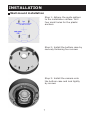
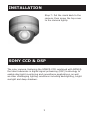
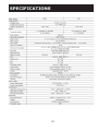
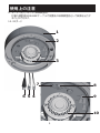
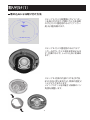
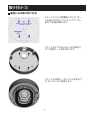
Vari-focal IR Vandal Dome
Instruction Manual
ZEIM-4000192G A.3_431U
CONTENTS
PRECAUTION.............................................................1
NOTES OF USE.......................................................... 2
INSTALLATION.......................................................... 5
SONY CCD & DSP.......................................................9
SPECIFICATION.........................................................11
10
WARNING
To avoid electrical shock, do not open the cabinet. Refer servicing
to qualified personnel only.
PRECAUTION
The lightening flash with arrowhead symbol, within an equilateral
triangle, is intended to alert the
user to the presence of uninsulated "dangerous voltage" within
the product's enclosure that may
be of sufficient magnitude to
constitute a risk of electric shock
to persons.
The exclamation point within an
equilateral triangle is intende-d
to alert the user to the presence of important operating
and maintenance (servicing)
instructions in the literature
accompanying the appliance
NOTE: This equipment has been
tested and found to comply with
the limits for a Class A digital
device, pursuant to Part 15 of
the FCC Rules. These limits are
designed to provide reasonable
protection against harmful
interference when the equipment
is operated in a commercial
environment. This equipment
generates, uses, and can radiate
radio frequency energy and, if not
installed and used in accordance
with the instruction manual, may
cause harmful interference to radio
communications.
Operation of this equipment in a
residential area is likely to cause
harmful interference in which
case the user will be required to
correct the interference at his own
expense.
FCC Caution: To assure continued compliance, (example – use
only shielded interface cables
when connecting to computer or
peripheral devices). Any changes
or modifications not expressly
approved by the party responsible
for compliance could void the
user’s authority to oper-ate this
equipment.
The serial number of this
product may be found on the
top of the unit. You should
note the serial number of this
unit in the space provided and
retain this book as a permanent
record of your purchase to aid
identification in the event of
theft.
Model No.
Serial No.
NOTES OF USE
Power Supply
You can use either AC 24V or DC 12V as power input. The camera automatically detects the power.When connecting the transformer, be sure to connect each
lead to the appropriate terminal. Wrong connection may cause malfunction and/or
damage to the video camera. Ground the unit or an irregular voltage may be generated in the AC power cable and may cause malfunction and/or damage to
the video camera.
Operating or storage location
Avoid shooting very bright objects (such as light fittings) for an extended period. Avoid operating or storing the unit in the following locations:
- Extremely hot or cold places (operating temperature: -10oC to +50oC)
- Close to sources of strong magnetism
- Close to sources of powerful electromagnetic radiation, such as radios
or TV transmitters
- Close to humid or excessively dusty places
- Where exposed to mechanical vibrations
- Close to fluorescent lamps or objects reflecting light
- Under unstale light sources (it may cause flickering)
Attaching the dome casing
Attach the dome casing with the supplied screw
Transportation
When transporting the camera, repack it as originally packed at the factory or
in materials equal in quality
Cleaning
-The dome cover is the optical part. Use a soft, dry cloth to remove the
finger prints or dust
-Use a blower to remove dust from the lens
-Clean the body with a dry soft cloth lf it is very dirty, use a cloth
damp ened with a small quantity of neutral detergent, then wipe dry
-Do not use volatile solvents such as alcohol,benzene or thinners as
they may damage the surface finishes
Water resistant
Use waterproof adhesive/tape to wind around the connections (threads)
between pipes to prevent water from entering.
NOTES OF USE
Using the camera outdoors
Make sure you seal the locations listed below with sealant (e.g., silicon sealant) to prevent moisture from getting inside the casing.
- The holes where the unit casing bottom is attached to a
ceiling or wall
- Conduit holes (side/bottom): you can seal the hole by using an
waterproof accessary.
- Joint surface of the camera casing gasket and unit casing.
Location and Function of Parts
1. Unit casing
The unit casing is made of die-cast aluminum and has conduit holes on the
side and bottom.
2. Safety cord
The safety cord prevents the dome casing from falling to avoid do harm to
people. Please do not remove the safety cord from the unit. If it is necessary
to remove, please remember to fasten the screws accompanied.
3. Zoom lever & Focus lever
Adjusts the camera range and focus. The lever itself is a screw and can be re
moved. Turning this screw all the way clockwise locks the position.
4. UTP-Unshield Twisted Pair(white/black wire)
Twisted Pair(TP) terminal (CAT.5E) for video signal. Usage of TP output re
quires a TP receiver at the other end of the TP line.
5. Power connector(red/black wire)
Connects to the external power source. (DC12V/AC24V)
6. BNC connector
Connects to the VIDEO IN connector of the Monitor Video Connector.
7. LEVEL adjustment switch
Use to compensate for the iris level.Turn toward L(low) to make the picture
darker. Turn toward H(high) to make the picture brighter
8. Mode setting DIP switch
The following DIP switches are set to defalut position(shaded) as shipped
from factory.
- BLC (backlight compensation) (lnitial setting: OFF)
When switched on, the function adjusts exposure to compensate for situa
tions where the subject is lit from behind.
- AGC (automatic gain control) (lnitial setting: ON)
The automatic gain function automatically adjusts picture in accordance with
the brightness of subject.
- DC/AES Mode switch (Always setting: ON)
This function is useless in the camera. - Flickerless (lnitial setting: OFF)
Flickerless reduces flickers when NTSC camera is used with 50Hz power
freqency and vice versa. Users can turn on the flickerless function.
NOTES OF USE
9. Monitor (MONITOR OUT) connector
You can connect to a monitor from this connector.You can adjust
the camera while looking at the image on the monitor. After ad
justing the camera, disconnect the cable.
10. IR Board
1
2
3
7
8
9
6 5 4
10
INSTALLATION
Ceiling mount installation
Step 1: Adhere the guide pattern
to the installation surface. Drill
one big and three small holes on
the soft wall.
Step 2: Install the camera onto
the ceiling and lock tightly by
screws.
Step 3: Press the grip portion to
remove the mask and rotate the
main bracket to adjust the pan
angle.
INSTALLATION
Step 4: Loosen the screw to adjust the tilt angle then tighten the
screw again
Step 5: Put the mask back to the
camera.
Step 6: Screw the top cover to the
camera tightly.
INSTALLATION
Wall mount installation
Step 1: Adhere the guide pattern
to the installation surface. Drill
four small holes for the plastic
anchors.
Step 2: Install the bottom case by
securely fastening four screws.
Step 3: Install the camera onto
the bottom case and lock tightly
by screws.
INSTALLATION
Step 4: Press the grip portion to
remove the mask and rotate the
main bracket to adjust the pan
angle.
Step 5: Loosen the screw to adjust the tilt angle then tighten the
screw again
Step 6: Adjust the camera zoom
to suitable position.
INSTALLATION
Step 7: Put the mask back to the
camera, then screw the top cover
to the camera tightly.
SONY CCD & DSP
The color camera, featuring the SONY® CCD combined with SONY®
the latest advances in digital signal processing (DSP) technology to
enable day/night monitoring and surveillance applications, as well
as other challenging lighting conditions including backlighting, bright
sunlight and deep shadows.
SPECIFICATIONS
10
バリフォーカルレンズ搭載
赤外線ドームカメラ
取扱説明書
目次
注意事項....................................................................1
使用上の注意.............................................................. 2
取り付け.................................................................... 5
SONY CCD & DSP.......................................................9
仕様..........................................................................11
10
警告
製品の修理は資格を持つ技術者のみにお求め下さい。本体を分解しないで下さい。
感電または他の危険を引き起こす可能性があります。
注意事項
注意
感電する危険があります。
開けないでください。
注意:本装置は、FCC基準パート15に準ず
るClass Aのデジタル電子機器の制限事
項に準拠しています。これらの制限事項
は、機器を商用環境で使用した場合に生
正三角形内部の矢印の記号の付いた稲 じる可能性のある電磁障害を規制するた
妻は、製品の筐体内部に感電させるに十 めに制定されたものです。本装置は高周
分な強さの、絶縁されていない「危険な 波エネルギーを生成し使用しています。ま
電圧」が存在することに注意を促すため た、高周波エネルギーを放射する可能性が
のものです。
あるため、指示に従って正しく設置しなか
った場合は、無線通信に障害を及ぼす可
能性があります。
住宅地域でこの機器を使用した場合、ユ
ーザーは自費で障害を是正する必要があ
ります。
正三角形内部の感嘆符は、機器に付属
するマニュアルに、重要な操作・保守(ア
フターサービス)に関する指示があるこ
とに注意を促すためのものです。
本製品のシリアル番号は、装置の上面
にあります。
この装置のシリアル番号は
本書の空きスペースに書き留め、盗難
にあった場合識別できるように購入の
記録として本書を保管してください。
モデル番号.
シリアル番号.
1
FCCの注意:常に準拠に従ってください(
例 – コンピュータや周辺装置に接続する
とき、シールドされたインターフェイスケー
ブルのみを使用してください。)FCC準拠
に責任を持つ第三者からの明確な許可を
受けることなく、本体に承認されていない
変更や改造が行われた場合には、本装置
を使用する権利が規制される場合があり
ます。
使用上の注意
電源装置
電源入力として、AC 24VとDC 12Vのどちらかを使用できます。カメラは電源を自動的に検出
します。トランスに接続するとき、各リードを必ず適切な端子に接続してください。接続を間違える
と、ビデオカメラの故障または損傷の原因となります。装置をアースするとAC電源ケーブルに不規
則な電圧が生成され、ビデオカメラが故障したり損傷する原因となります。
操作または保管場所
長時間明るい物体(照明器具、など)を照らさないでください。 次の場所で装置を操作したり
保管したりしないでください。
- 極端に暑いまたは寒い場所(動作温度:-10℃ ~ +50℃)
- 強い磁場の近く
- ラジオやテレビのトランスなど、強い電磁放射線源の近く
- 湿気やひどく埃っぽい場所の近く
- 機械的振動にさらされる場所
- 蛍光灯または光を反射する物体の近く
- 不安定な光源下(ちらつきの原因となります)
ドームケースの取り付け
付属のねじでドームケースを取り付けます
輸送
カメラを輸送するとき、工場で梱包された材料または同等の品質の材料で再び梱包してくださ
い。
洗浄
- ドームカバーは光学部品です。指紋や埃を取り除くには、乾いた柔らかい布を使用してください
- レンズから埃を取り除くには、ブロワーを使用してください
- 本体は乾いた柔らかい布できれいにしてください。汚れがひどい場合、中性洗剤を少量、染み
込ませた布を使い、その後乾いた布で拭いてください。
- アルコール、ベンジンまたはシンナーなどの揮発性溶剤は表面仕上げを損傷させる可能性が有
る為、使用しないで下さい。
耐水性
水が入り込まないように、防水接着剤/テープを使用して、パイプ間の接続(ねじ山)の
回りに巻き付けてください。
2
使用上の注意
カメラを屋外で使う
湿気がドームケース内部に入り込まないように、
シーリング剤(シリコンシーリング剤、など)
で以下に記した箇所を保護してください。
- ドームケースの底面が天井や壁に取り付けられる通線口。
- ケーブルの穴(側面/底面):防水アクセサリを使って穴を密封することができます。
- カメラケーシングのパッキンと装置ケースの接合面。
部品の場所と機能
1. ドームケース
ドームケースの材料はアルミダイカストで、側面と底面にケーブル用の穴が開いています。
2. 落下防止コード
落下防止コードにより、
ドームケースが落ちて人に危害を与えるのを防ぐことができます。
カ
メラ本体から落下防止コードを外さないでください。取り外す必要がある場合、付属のねじ
を締めるのを忘れないでください。
3. ズームレバーとフォーカスレバー
映像の画角とピントを調整します。
レバーはねじ式でねじを緩めれば左右に調整が可能で
す、調整後はねじをしっかりと締め固定して下さい。
4. UTP被膜無しのツイストペアケーブル(白/黒線)
ビデオ信号は、ツイストペアケーブルTP端子(CAT.5E)
でTP端子を使用する為にはもう一方
の端にTPレシーバーが必要となります。
5. 電源コネクタ
(赤/黒ワイヤ)
外部電源装置に接続します。(DC12V/AC24V)
6. BNCコネクタ
ビデオ出力のBNCコネクタです。
ビデオ入力コネクタに接続します。
7. レベル調整ボリウム
アイリスレベル(明るさ)の調整に使用します。L(低)方向に回すと映像が暗くなります。
ま
た、H(高)方向に回すと映像が明るくなります。
8. モード設定DIPスイッチ
次のDIPスイッチは、工場出荷時のデフォルト位置に設定されています。
- BLC(逆光補正)
(初期設定:オフ)
この機能は、被写体の背景の明るさにより、被写体が見やすくなります。逆光補正機能は測
光エリアを固定しますので被写体の条件によっては、ONにしても映像に変化が無い場合が
あります。
- AGC(自動ゲインコントロール)
(初期設定:オン)
被写体が暗くなり映像出力レベルが下がってきた時に自動で感度調整を行い映像出力レベ
ルを保ちます。
- DC/AESモードスイッチ(常に設定:オン)
このスイッチは、本製品では使用できません。
- フリッカレス機能(初期設定:オフ)
AC100V/50Hz電源地域(東日本)では、蛍光灯(放電灯)等照明下での撮像の座愛、画面のち
らつきが起こります。
この現象をフリッカと言います。
スイッチをONにすると画面のちらつき
が目立たなくなります。
3
使用上の注意
9. モニター出力コネクタ
(映像調整用)
付属の調整用MON-BNCケーブルで設置後の映像調整用として映像を出力す
ることができます。
10. IRボード
1
2
3
7
8
9
6 5 4
10
4
取り付け
(1)
埋め込みによる取り付け方法
ステップ1:カメラ設置面にガイドパター
ンを貼り付けます、内側にカメラ本体用
の穴とカメラ固定用のねじ穴(アンカー
用)を3箇所開けます。
ステップ2:カメラ固定用のねじ穴にア
ンカーを打ち、
カメラ本体を埋め込みま
す。付属のねじで、
しっかりとねじを締め
ます。
ステップ3:内側の内部マスクを手で矢
印の方向に押し変形させ、両側の固定ピ
ンよりマスクを外します。
メインブラケットを回転させ映像のパン
角度を調整します。
5
取り付け
(2)
ステップ4:ねじを緩めて映像の傾きを
調整します。調整後、ねじをしっかりと締
めます。
ステップ5:5ページのステップ3と同様
に内部マスクを変形させカメラに装着さ
せます。
ステップ6:上部カバーをカメラ本体に取
り付け、付属の特殊レンチでしっかりと
締めます。
6
取り付け
(3)
露出による取り付け方法
ステップ1:カメラ設置面にガイドパター
ンを貼り付けます、
プラスチックアンカー
用の穴を4箇所開けます。
ステップ2:4つのねじをしっかり締め付
けて、底面ケースを取り付けます。
ステップ3:底面ケースにカメラを取り付
け、ねじでしっかり固定します。
7
取り付け
(4)
ステップ4:内側の内部マスクを手で矢
印の方向に押し変形させ、両側の固定ピ
ンよりマスクを外します。
メインブラケットを回転させ映像のパン
角度を調整します。
ステップ5:ねじを緩めて映像の傾きを
調整します。調整後、ねじをしっかりと締
めます。
ステップ6:ズームレバーを半時計回りに
緩め、理想の画角になる様にレンズの焦
点距離を調整します。
また、調整後にレ
バーを締めロックしてください。
フォーカスレバーを半時計回りに緩め、
映像のピントを調整します。
また、調整後
にレバーを締めロックしてください。
8
取り付け
(5)
ステップ7:5ページのステップ3と同様
に内部マスクを変形させカメラに装着さ
せます。上部カバーをカメラ本体に取り
付け、付属の特殊レンチでしっかりと締
めます。
SONY CCD & DSP
デジタル信号処理(DSP)テクノロジの最新の進歩を示すSONY®を組み込んだ
SONY® CCDを採用することにより、
このカラーカメラは、昼夜の監視と査察用
途、およびバックライティング、昼夜を問わない環境下など、その他の困難な照明
条件でも使用することができます。
9
仕様
TV方式
画像システム
CCDサイズ
撮像素子
有効画素数
電気システム
走査システム
同期方式
水平解像度
内蔵レンズ
アイリスコントロール
レンズ画角
ガンマ補正
2:1インタレース V:59.94Hz
内部
560 TV本
f=3.7∼12mm、F1.4 DC アイリスバリフォーカル D/Nレンズ
ダイレクトドライブ
水平: 76.92°(ワイド)∼22.73(
°望遠)
、垂直: 56.89°(ワイド)∼17.07°(望遠)
0.7ルクス (AGCオン)@50 IRE:
0ルクス (IR LED電源オン)
50dB以上(AGCオフ)
自動: (2500°K∼9500°K)
最低被写体照度
S/N比
ホワイトバランス
電子シャッター
UTP
フリッカレス
逆光補正
AGC
Day/Nightモード
ビデオ出力
モニター出力
IR LED
IR波長
IR照射距離
IR LED照射照度
LED寿命
電源システム
1/60秒
1/50秒
パッシブ: 300メートル
オン/オフ
オン/オフ
オン/オフ
オート
1Vppコンポジット出力、75オーム
1Vppコンポジット出力、75オーム
ハイライト LED x 18PCS
30m(実写距離10-15m)
オン:10Lx以下
20,000時間(常温25℃時)
電源
消費電力
7.0W(最大)
環境
動作温度
動作湿度
保管温度
-10℃∼50℃
30%∼90%以下
-20℃∼60℃
本体
外形寸法(Φ×H)
質量
2:1インタレース V:50Hz
約φ160mm×(H)115mm
約1,150g
耐衝撃
1000KG
防水規格
10


![[PRODUCT SHOWCASE] デジタルカメラ購入ガイド](http://vs1.manualzilla.com/store/data/006552313_2-f2225a519b84cd1bee2cdb557cdf2ac2-150x150.png)