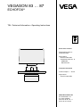
1
VEGASON 83 … 87
ECHOFOX®
TIB • Technical Information • Operating Instructions
Pulse-echo sensors
Digital transmission of
measuring data
Approvals for
- dust-Ex areas StEx
- hazardous areas acc. to
- CENELEC
- ElexV Zone 0
Compact instrument
Current output 0 … 20 mA
Approval for
- dust-Ex areas StEx
VEGA Grieshaber KG
Am Hohenstein 113
D-77761 Schiltach
Phone 0 78 36 / 50 - 0
Fax 0 78 36 / 50 201
2
VEGASON 83 … 87
Contents
Contents
1 Introduction
1.1
Contents of the instruction manual ..................................................................................................................... 4
1.2
Safety information ............................................................................................................................................... 4
2 Product description
2.1
Function and configuration .................................................................................................................................. 4
2.2
Types and versions ............................................................................................................................................. 5
2.3
Configuration of a measuring system, sensor in not-Ex-area ............................................................................. 8
2.4
Configuration of a measuring system, sensor in Ex-area ................................................................................... 9
2.5
Order code for sensors ..................................................................................................................................... 10
2.6
Technical data of the sensors ............................................................................................................................ 11
2.7
Configuration with compact instrument ............................................................................................................. 14
2.8
Order code for compact instrument ................................................................................................................... 15
2.9
Technical data of compact instruments ............................................................................................................. 16
2.10
Dimensional drawings ....................................................................................................................................... 18
2.11
Approvals .......................................................................................................................................................... 22
3 Environment
3.1
Installation recommendations relating to liquid tank / vessels .......................................................................... 23
3.2
Installation recommendations relating to solid silos .......................................................................................... 25
4 Electrical connection
4.1
Connection example of sensors ........................................................................................................................ 26
4.2
Connection example of Ex-sensors .................................................................................................................. 27
4.3
Connection example of compact instruments ................................................................................................... 29
5 Set-up
5.1
Sensor and signal conditioning instrument (e.g. VEGAMET) ........................................................................... 30
5.2
Sensor and processing system (VEGALOG 571) ............................................................................................. 30
5.3
Compact instrument .......................................................................................................................................... 30
VEGASON 83 … 87
3
1 Introduction / 2 Product description
1
Introduction
1.1 Contents of the instruction manual
The Technical Information / Operating Instructions is
called TIB. It contains all necessary information for correct
- installation
- connection
- set-up
- optimization
of the pulse-echo-sensors VEGASON …. V… or pulseecho compact instrument VEGASON … K….
VEGA regularly revises the contents of TIBs as technical
improvements are made to the instruments.
1.2 Safety information
The described module must only be inserted and operated
as described in this TIB. Please note that other action can
cause damage for which VEGA does not take
responsibility.
The signal-to noise ratio is optimized by digital signal
processing methods with mathematic algorithms (DSP).
The automatic configuration of a user specific data base
enables an optimum adaption to the respective
application.
The use of fuzzy-logic for echo evaluation ensures a
reliable determination of the level. False echoes, e.g. from
stirrers or other installations are detected and are not
included in the generation of the measured value.
These measuring data are transmitted digitally to
respective signal conditioning instruments or processing
systems and processed.
The operation of the sensors is made via the signal
conditioning instrument VEGAMET or via a PC
(VEGACONNECT necessary).
Compact instruments are additionally equipped with an
integral output of the measuring data and make a current
output 0 … 20 mA available.
The operation of the compact instrument is only possible
with PC via VEGACONNECT.
2
Product description
2.1 Function and configuration
Function
The VEGASON … sensor systems or compact
instruments are used for continuous and non-contact level
measurement.
Short sound impulse packets are emitted by the
transducer of the pulse-echo sensor. The combined
emitter and receiver system detects the pulses reflected
by the product.
The running period of the ultrasonic pulses is directly proportional to the distance between sensor and measured
product.
Configuration
Flange version
The sensor or compact instruments consist of a housing,
integrated therein the above electronics and all required
terminals, a mounting flange and a transducer.
Housing, flange and transducer are designed acc. to the
type.
Separate version
The separate version consists of a housing with integral
electronics and all necessary terminal and mounting plate.
Transducer with mounting tube and connection cable as
separate modular unit. The transducers differ acc. to the
various types.
The signal processing ECHOFOX® uses modern methods
of signal analysis to process the reflected ultrasonic
pulses.
4
VEGASON 83 … 87
2 Product description
2.2 Types and versions
VEGASON 84 FK
VEGASON 84 FV
VEGASON 83 FK
VEGASON 83 FV
Flange version with flange size DN 100, transducer integral in flange, plastic housing with integral ECHOFOX®sensor electronics.
Suitable for a number of applications and mounting
positions,
- mounting directly on the vessel ceiling (tank, silo) or on
existing sockets
- positioning on fix points above the vessels etc.
Measuring range 0,7 m … 10 m
(see section 3 Evironment).
VEGASON 83 FV Ex, 83 FV Ex 0
as VEGASON 83 FV, however housing of sensor
electronics and transducer made of stainless steel 1.4305
Flange version with flange size DN 150, transducer below
the flanges, plastic housing with integral ECHOFOX®sensor electronics.
Suitable for a number of applications and mounting
positions,
- mounting directly on the vessel ceiling (tank, silo) or on
existing sockets
- positioning on fix points above the vessel etc.
Measuring range 0,7 m … 20 m
(see section 3 Environment).
VEGASON 84 FK StEx
VEGASON 84 FV StEx
as VEGASON 84 FK or FV, however additionally approved
for the use in dust-Ex areas StEx (see section 2.11
Approvals).
Suitable for the use in hazardous areas (see section 2.11
Approvals).
VEGASON 84 FV Ex, 84 FV Ex 0
VEGASON 83 FV Ex B, 83 FV Ex0 B
as VEGASON 83 FV Ex or FV Ex 0, however with integral
overvoltage arrester of sensor electronics.
Flange version with flange size DN 150, transducer integral in flange, housing of sensor electronics and
transducer made of stainless steel 1.4305.
Suitable for the use in hazardous areas (see section 2.11
Approvals).
VEGASON 83 … 87
5
2 Product description
VEGASON 84 FV Ex B, 84 FV Ex0 B
as VEGASON 84 FV Ex or FV Ex 0, however with integral
overvoltage arrester of sensor electronics.
Compact instrument
VEGASON 85 FK
VEGASON 85 FV
Flange version with flange size DN 150, transducer below
the flanges, plastic housing with integral ECHOFOX®sensor electronics.
Suitable for a number of applications and mounting
positions,
- mounting directly on the vessel ceiling (tank, silo) or on
existing sockets
- positioning on fix points above the vessels etc.
Measuring range 1,0 m … 30 m
(see section 3 Environment).
VEGASON 87 FK
VEGASON 87 FV
Flange version, flange size ø 450 mm, triple transducer
divided into emission and receipt unit, reset as described
under VEGASON 85 FV.
Measuring range 0,4 m … 60 m
(see section 3 Environment).
VEGASON 87 FK StEx
VEGASON 87 FV StEx
as VEGASON 87 FK or FV, however additionally approved
for the use in dust-Ex areas StEx (see section 2.11
Approvals).
VEGASON 85 FK StEx
VEGASON 85 FV StEx
as VEGASON 85 FK or FV, however additionally approved
for the use in dust-Ex areas StEx (see section 2.11
Approvals).
6
VEGASON 83 … 87
2 Product description
VEGASON 83 GK
VEGASON 83 GV
Separate version, transducer and housing are separated.
An ECHOFOX®-sensor electronics is integrated in the
housing. The transducer is provided with a fixing tube
(thread G 1). It can be mounted in a small hole (ø 35 mm)
at the vessel ceiling (tank/silo).
As option the transducer can be screwed with a swivelling
holder (DN 150) and can be optimally adapted to the
installation conditions.
Measuring range 0,7 m … 10 m
(see section 3 Environment).
VEGASON 84 GK
VEGASON 84 GV
as VEGASON 83 GKor GV, however
measuring range 0,7 m … 20 m
VEGASON 84 GK StEx
VEGASON 84 GV StEx
as above, however additionally approved for the use in
dust-Ex areas StEx (see section 2.11 Approvals).
VEGASON 85 GK
VEGASON 85 GV
as VEGASON 83 GK or GV, however
measuring range 1,0 m … 30 m
VEGASON 85 GK StEx
VEGASON 85 GV StEx
as above, however additionally approved for the use in
dust-Ex areas StEx (see section 2.11 Approvals).
VEGASON 87 GK
VEGASON 87 GV
as VEGASON 83 GK or GV, however triple transducer
divided into emission and receipt unit, rest as described
under
measuring range 0,4 m … 60 m
VEGASON 87 GK StEx
VEGASON 87 GV StEx
6
as above, however additionally approved for the use in
dust-Ex areas StEx (see section 2.11 Approvals).
VEGASON 83 … 87
7
2 Product description
2.3 Configuration of a measuring system, sensor in not-Ex-area
Generally a measuring system consists of two components
- a local sensor and
- a signal conditioning instrument or processing system
The kind of signal conditioning instrument or processing system depends on the installation conditions.
Sensor(s)
VEGASON 83 … 87
1
6 … 10
1 … 5
Signal conditioning
instrument e.g.
VEGAMET 514 V
(VEGAMET 407 V)
11 … 15
Processing system
VEGALOG 571
RS
232
EV-input card
(via additionally EV-input cards max. 3 x 5 = 15 sensors
each can be connected)
VEGACONNECT
CPU-central unit
4
PC
Sensor(s) and signal conditioning instrument or processing system are connected via a two-wire line. The power supply
of the sensor or the sensors is ensured via this line and the measuring data are transmitted digitally to the signal
conditioning instrument or processing system.
The indicating and operating surface VEGA Visual Operating, installed on a PC ensures a simple and comfortable
configuration and parameter adjustment of the respective measuring system.
VEGACONNECT can be connected to respective sockets of the signal conditioning instrument or the sensor. If necessary, it is possible to connect VEGACONNECT directly to the two-wire line (signal conditioning instrument … sensor).
8
VEGASON 83 … 87
2 Product description
2.4 Configuration of a measuring system, sensor in Ex-area
In this application a measuring system consists of three components
- a local Ex-sensor in the Ex-area
- a safety barrier and
- a signal conditioning instrument or processing system in the not-Ex-area
The kind of signal conditioning instrument or processing system mainly depends on the control and process technical
requirements.
Sensor(s)
VEGASON 83 und 84
1
1 … 5
6 … 10
etc.
Ex-area
4
4
4
4
4
Not-Ex-area
Separator Type 146 or
VEGATRENN 546
1
1
Signal conditioning
instrument e.g.
VEGAMET 514 V
(VEGAMET 407 V)
…
5
6
…
10 etc.
Processing system
VEGALOG 571
usw.
RS
232
1. EV-input card
2. EV-input card
(via additionally EV-input card 5 sensors each can be connected)
VEGACONNECT
CPU-central unit
4
PC
Each sensor is connected to the respective signal conditioning instrument or processing system via a separator type 146
or VEGATRENN 546. The separator provides two intrinsically safe circuits. These circuits provide the power supply of the
sensor and the digital transmission of measuring data to the signal conditioning instrument or processing system.
The indicating and operating surface VEGA Visual Operating, installed on a PC ensures a simple and comfortable
configuration and parameter adjustment of the respective measuring system.
VEGASON 83 … 87
9
2 Product description
2.5 Order code for sensors
2.5.1 VEGASON …V / …V StEx
Type
8 3
8 4
8 5
8 7
Measuring range
.................. 0,7 … 10 m
.................. 0,7 … 20 m
.................. 1,0 … 30 m
.................. 0,4 … 60 m
Version
F Flange version
G Separate version
Approvals
. X without
E X S . X StEx for Zone 10 (only for VEGASON 84 … 87)
Flange size
E DN 100 PN 16 (for VEGASON 83)
F DN 150 PN 16 (for VEGASON 84 and 85)
U ø 450 (for VEGASON 87)
Y Others
Flange material
A Aluminium (for StEx-version)
P PPh
Y Others
S O N
V
E Z
Order no. for VEGASON … V
2.5.2 VEGASON … FV Ex…
Type
8 3
8 3
8 4
8 4
S O N
10
F
F
F
F
V
V
V
V
E
E
E
E
X
CENELEC EEx d e ia IIB T6 ..........
X 0 PTB Zone 0 EEx d e ia IIB T6 ........
X
CENELEC EEx d e ia IIB T6 ..........
X 0 PTB Zone 0 EEx d e ia IIB T6 ........
Options
X without
B with overvoltage arrester
.
X V V V
Measuring range
0,7 … 10 m
0,7 … 10 m
1,1 … 20 m
1,1 … 20 m
Order no. for VEGASON … FV Ex…
VEGASON 83 … 87
2 Product description
2.6 Technical data of the sensors
2.6.1 VEGASON 83 … 87 FV, 84 … 87 FV StEx
VEGASON 83 … 87 GV, 84 … 87 GV StEx
Approvals
see section 2.11 Approvals
Power supply
via signal conditioning instrument
via processing system
Operating voltage
Power consumption
VEGAMET … with digital transmission of measuring data
VEGALOG 571 with EV-input cards
max. 36 V DC
max. 200 mA
Measuring range
VEGASON
Min. distance for
83 FV
liquids and
solids
granulation ≥ 5 mm 0,7 m
granulation ≤ 5 mm 0,8 m
Max. distance dependent on product and process
10 m
83 GV
84 …
85 …
87 …
0,5 m
0,6 m
10 m
0,7 m
1,0 m
20 m
1,0 m
1,2 m
30 m
0,4 m
0,4 m
60 m
1 mm
33 kHz
0,6 sec.
12°
1 mm
22 kHz
0,7 sec.
12°
1 mm
16 kHz
1,0 sec.
15°
1 mm
16 kHz
1,5 sec.
3,5°
Measuring data
Measuring resolution
Measuring frequency
Measuring rate
Radiation angle related to –3 dB
1 mm
33 kHz
0,6 sec.
12°
Error limits
Linearity error relating to the adjustment
Temperature error of the electronics
< 0,1 % of measuring range
0,015 %/10 K of measuring range
Materials
VEGASON
Housing and cover of electronics
Flange
Transducer housing
Impedance adapter
Transducer fixing tube
- Type83
- Type 84 and 85
- Type 87
Dimensions and weights
Flange size
- Type 83
- Type 84 and 85
- Type 87
Thread of the fixing tube
Total weight of sensors
- Type 83 … 85
- Type 87
Temperature reaction
VEGASON … StEx-version
At an ambient temperature
- on the transducer in Zone 10
- on the housing (electronics) in Zone 11
VEGASON 83 … 87
FV
PBT
PPh
PVDF
PE
GV
PBT
–––
PVDF
PE
StEx
PBT
St 37 galv. or Alu
PVDF
PE
–––
–––
–––
PVDF
RCH 1000
St 37 galvanized
St 37 galvanized
St 37 galvanized
St 37 galvanized
DN 100 PN 16
DN 150 PN 16
ø 450
–––
–––
–––
–––
G1A
DN 100 PN 16
DN 150 PN 16
ø 450
–––
appr. 6 kg
appr. 12 kg
appr. 6 kg
appr. 12 kg
appr. 6 kg
appr. 12 kg
40°C the max. temperature to be adjusted
45°C is reached and
55°C is reached
11
2 Product description
Ambient conditions
VEGASON
Ambient temperature related to
- transducer in Zone 10
- housing (electronics) in Zone 11
Storage and transport temperature
Protection
- of transducer
- the housing (electronics) generally
certified
- transducer
- housing
Overvoltage class
Protection class
Max. vessel pressure related to
- Type 83
- Type 84 and 85
- Type 87
Connection line
VEGASON … FV-version
Sensor to signal conditioning instrument /
processing system
VEGASON … GV-version
Transducer to sensor electronics
- Type 83 … 85
- Type 87
Sensor electronics to signal conditioning
instrument / processing system
Temperature sensor
Electrical connection
Terminals for the connection lines
Terminals for the earth connection
Cable entry
12
FV
GV
StEx
-20°C … +80°C
-20°C … +60°C
-20°C … +80°C
-20°C … +80°C
-20°C … +60°C
-20°C … +80°C
-20°C … +75°C
-20°C … +60°C
-20°C … +80°C
IP 67
IP 67
IP 67
IP 67
IP 65
IP 65
–––
–––
III
II
–––
–––
III
II
IP 65
IP 54
III
II
0,5 bar
0,5 bar
0,3 bar
1,0 bar
0,5 bar
0,5 bar
–––
0,5 bar
0,5 bar
2 pole, maximal 20 Ohm/line
standard coax cable type RG 58
standard length 5 m
max. length 300 m
4 x 0,38 mm2, 1 screened wire
standard length 5 m, max. length 35 m
cable diameter 8 mm
2 pole, max. 20 Ohm/line
each integrated in the transmitter
with GV-version via connected connection line
above connection line
for max. 1,5 mm2
for max. 4,0 mm2
1 x Pg 13,5 for all FV-versions
2 x Pg 13,5 for all GV-versions
VEGASON 83 … 87
2 Product description
2.6.2 VEGASON 83 and 84 Ex, Ex0
VEGASON 83 and 84 Ex B, Ex0 B
Approvals
see section 2.11 Approvals
Power supply
via separator
Supply via
Flame proofing
Type 146 or VEGATRENN 546
2 intrinsically safe circuits of category ib IIB
EEx de ia IIB T6 (see also section 2.11)
Measuring range
VEGASON
Min. distance of liquids
Max. distance dependent on product and process
83
0,7 m
10 m
84
1,1 m
20 m
Measuring data
Measuring resolution
Measuring frequency
Measuring rate
Radiation angle related to –3 dB
1 mm
33 kHz
1,1 sec.
12°
1 mm
22 kHz
1,5 sec
12°
Error limits
Linearity error relating to the adjustment
Temperature error of the electronics
< 0,1 % of measuring range
0,015 %/10 K of measuring range
Materials
Housing of electronics
Flange
Diaphragm
Flange sealing
1.4305
1.4305
1.4531
Viton
Dimensions and weights
Flange size
- Type 83
- Type 84
Total weight of the sensors
Ambient conditions
Max. permissible ambient temperature
- on the transducer
- on the housing (electronics)
Storage and transport temperature
Protection
Max. vessel pressure
- Type 83
- Type 84
Vessel pressures and ambient temperature
under Ex-conditions
DN 100 PN 16
DN 150 PN 16
at DN 100 approx. 17 kg
at DN 150 approx. 21 kg
+80°C
+60°C
-20°C … +80°C
IP 67
2 bar
1 bar
see respective conformity certificate
Connection line
Sensor … separator
Resistance per conductor
Temperature sensor and its connection
2 x 2 pole
max. 7,5 Ohm
integrated int he respective sensor
Electrical connection
Terminals for the connection line
Terminals for earth connection
Cable entry
max. 1,5 mm2
max. 4,0 mm2
1 x Pg 13,5
VEGASON 83 … 87
13
2 Product description
2.7 Configuration with compact instrument
As described under "2 Product description" the compact instruments are equipped with an integral processing of
measuring data. A current output 0 … 20 mA is available.
First of all each compact instrument must have a voltage supply. The current output can be directly connected to
indicators or process control systems.
VEGASON 83 … 87
1
2
3
4
usw.
Power supply
Ri
Processing
one current output 0 … 20 mA each
(e.g. for consumers with low inner resistance)
during the
adjustment
Ri = min. 100 Ohm
VEGACONNECT
PC
The indicating and operating surface VEGA Visual Operating, installed on a PC ensures a simple and comfortable
configuration as well as operator supporting parameter adjustment of the compact instruments.
Therefore it is necessary to connect the computer via VEGACONNECT directly with the respective compact instruments.
A digital signal is superimposed to the current output. The adjustment of the sensor can be also carried out via the
current output. For indication and processing systems with an inner resistance of less than 100 Ohm a respective series
resistor must be connected for the time of adjustment.
14
VEGASON 83 … 87
2 Product description
2.8 Order code for compact instrument
2.8.1 VEGASON …K / …K StEx
Type
8 3
8 4
8 5
8 7
S O N
Measuring range
.................. 0,7 … 10 m
.................. 0,7 … 20 m
.................. 1,0 … 30 m
.................. 0,4 … 60 m
Version
F Flange version
G Separate version
Approvals
. X without
E X S . X StEx for Zone 10 (only for VEGASON 84 … 87)
Power supply
E 110 V AC
A 230 V AC
I 24 V AC, 16 … 36 V DC
X Others
Flange size
E DN 100 PN 16 (for VEGASON 83)
F DN 150 PN 16 (for VEGASON 84 and 85)
U ø 450 (for VEGASON 87)
Y Others
Flange material
A Aluminium (for StEx-version)
P PPh
Y Others
K
VEGASON 83 … 87
E
Order no. for VEGASON … K
15
2 Product description
2.9 Technical data of compact instruments
2.9.1 VEGASON 83 … 87 FK, 84 … 87 FK StEx
VEGASON 83 … 87 GK, 84 … 87 GK StEx
Approvals
see section 2.11 Approvals
Power supply
Standard
Option
Measuring range
VEGASON
Min. distance of liquids
and solids
Unenn
Unenn
24 V AC (–15 %, +10 %), 50/60 Hz, 10 VA
24 V DC (16 … 36 V), 8 W
230 V AC, (–10 %, +5 %), 50/60 Hz, 10 VA
110 V, 130 V, 240 V AC (–15 %, +10 %),
50/60 Hz, 10 VA
83 FK
83 GK
84 …
85 …
87 …
0,7 m
0,8 m
10 m
0,5 m
0,6 m
10 m
0,7 m
1,0 m
20 m
1,0 m
1,2 m
30 m
0,4 m
0,4 m
60 m
Measuring data
Measuring resolution
Measuring frequency
Measuring rate
Radiation angle related to –3 dB
1 mm
33 kHz
0,6 sec.
12°
1 mm
33 kHz
0,6 sec.
12°
1 mm
22 kHz
0,7 sec.
12°
1 mm
16 kHz
1,0 sec.
15°
1 mm
16 kHz
1,5 sec.
3,5°
Current output
Range
Load
Resolution of D/A-conversion
0 … 20 mA
max. 400 Ohm
0,025 % of adjustment
Error limits
Linearity error relating to the adjustment
Temperature error of the electronics
< 0,1 % of measuring range
0,015 %/10 K of measuring range
granulation ≥ 5 mm
granulation ≤ 5 mm
Max. distance dependent on product and process
Materials
VEGASON
Housing and cover of the electronics
Flange
Transducer housing
Impedance adapter
Transducer fixing tube
- Type 83
- Type 84 and 85
- Type 87
Dimensions and weights
Flange size
- Type 83
- Type 84 and 85
- Type 87
Thread of the fixing tube
Total weight of the sensor
- Type 83 … 85
- Type 87
Temperature reaction
VEGASON … StEx-version
At an ambient temperature of
- transducer in Zone 10 of
- housing (electronics) in Zone 11 of
16
FK
PBTP
PPh
PVDF
PE
GK
PBTP
–––
PVDF
PE
StEx
PBTP
St 37 galv. or Alu
PVDF
PE
–––
–––
–––
PVDF
RCH 1000
St 37 galvanized
St 37 galvanized
St 37 galvanized
St 37 galvanized
DN 100 PN 16
DN 150 PN 16
ø 450
–––
–––
–––
–––
G1A
DN 100 PN 16
DN 150 PN 16
ø 450
–––
appr. 6 kg
appr. 12 kg
appr. 6 kg
appr. 12 kg
appr. 6 kg
appr. 12 kg
40°C the max. temperature to be adjusted
45°C is reached and
55°C is reached
VEGASON 83 … 87
2 Product description
Ambient conditions
VEGASON
Ambient temperatures related to
- transducer in Zone 10
- housing (electronics) in Zone 11
Storage and transport temperature
Protection
- of the transducer
- of the housing (electronics) generally
certified
- transducer
- housing
Overvoltage class
Protection class
Max. vessel pressure related to
- Type 83
- Type 84 and 85
- Type 87
Connection line
VEGASON … FK-versions
Power supply
VEGASON … GK-versions
Transducer to sensor electronics
- Type 83 … 85
- Type 87
Temperature sensor
Electrical connection
Terminals for the connection lines
Terminals for earth connection
Cable entry
VEGASON 83 … 87
FK
GK
StEx
-20°C … +80°C
-20°C … +60°C
-20°C … +80°C
-20°C … +80°C
-20°C … +60°C
-20°C … +80°C
-20°C … +75°C
-20°C … +60°C
-20°C … +80°C
IP 67
IP 67
IP 67
IP 67
IP 65
IP 65
–––
–––
III
II
–––
–––
III
II
IP 65
IP 54
III
II
0,5 bar
0,5 bar
0,3 bar
1,0 bar
0,5 bar
0,5 bar
–––
0,5 bar
0,5 bar
2/3 pole, standard cable
standard coax cable type RG 58
standard length 5 m
max. length 300 m
4 x 0,38 mm2, 1 screened wire
standard length 5 m, max. length 35 m
cable diameter 8 mm
each integrated in the transmitter
with GK-version connected via above
connection line
for max. 1,5 mm2
for max. 4,0 mm2
2 x Pg 13,5 for all FK-versions
3 x Pg 13,5 for all GK-versions
17
2 Product description
2.10 Dimensional drawings
Standard- and StEx-versions
(Dimensions in mm)
260 x 150
45˚
Min. distance
ø180
ø220
Flange acc. to DIN - DN 100 PN 16 (ANSI 3 1 /2 " 150 psi)
260 x 150
45˚
Min. distance
95
0,7…1,2 m
20
247
ø2
2
VEGASON 84 and 85 FV…
VEGASON 84 and 85 FK…
ø110
2
30
0,7…0,8 m
247
ø18
VEGASON 83 FV
VEGASON 83 FK
ø145
ø240
ø285
Flange acc. to DIN - DN 150 PN 16 (ANSI 6" 150 psi)
260 x 150
45˚
Min. distance
95
0,4 m
20
272
ø22
VEGASON 87 FV…
VEGASON 87 FK…
ø450
Installation approx. 320
ø410
18
VEGASON 83 … 87
2 Product description
Standard- and StEx-versions
(Dimensions in mm)
Electronics unit
260 x 150
ø140
ø6
,4
253
90
ø162
VEGASON 83 GV
VEGASON 83 GK
~155
28
Swivelling holder
Flange
DN 150 PN 16
Standard version
ø95
Transducer
SW 73
SW 73 R Ex
VEGASON 83 … 87
0,5…0,6 m
90
45
138
Thread G 1 A
Min. distance
19
2 Product description
Standard- or StEx-versions
(Dimensions in mm)
Swivelling holder
~155
28
VEGASON 84 and 85 GV…,
84 and 85 GK…
Flange
DN 150 PN 16
StEx-version
Standard version
Thread G 1 A
0,7…1,2 m
138
82
138
28
Thread G 1 A
ø145
Transducer
SW 74
SW 75
VEGASON 87 GV…
VEGASON 87 GK…
Transducer
SW 74 R Ex
SW 75 R Ex
Min. distance
~155
28
Swivelling holder
Flange
DN 150 PN 16
StEx-version
Standard version
Thread G 1 A
Installation approx. 320
20
0,4 m
176
60
138
28
Thread G 1 A
Min. distance
VEGASON 83 … 87
2 Product description
Ex-version
(Dimensions in mm)
VEGASON 83 FV Ex, Ex B
VEGASON 83 FV Ex 0, Ex 0 B
Pg 16
ø1
8
335
ø154
80
ø220
20
0,7 m
Flange
DN 100 PN 16
45˚
Min. distance
ø180
VEGASON 84 FV Ex, Ex B
VEGASON 84 FV Ex 0, Ex 0 B
Pg 16
335
ø154
45˚
2
ø2
1,1 m
ø285
22
60
Flange
DN 150 PN 16
Min. distance
VEGASON 83 … 87
ø240
21
2 Product description
2.11 Approvals
If measuring systems acc. to the following approvals are installed, the respective legal documents have to be observed.
The documents are enclosed to the respecitve measuring system.
StEx-approval
For measuring systems in dust-Ex areas.
- pulse-echo sensor
VEGASON 84 … 87 FK StEx and GK StEx
VEGASON 84 … 87 FV StEx and GV StEx
defined in the type approval BVS 93.Y.8005
- signal conditioning instrument
- processing system
VEGAMET … with digital transmission of measuring data
VEGALOG 571 with EV-input cards
- auxiliary level switch
all VEGASEL with current input 0/4 … 20 mA
Ex-approval
For measuring system in hazardous areas,
certificated acc. to
- CENELEC
- ElexV Zone 0 (Germany)
- pulse-echo sensor
VEGASON 83 and 84 FV Ex
VEGASON 83 and 84 FV Ex B
- power supply via
separator type 146 or VEGATRENN 546
acc. to conformity certificate PTB-no. Ex-93.C.4025
defined in the conformity certificate PTB-no. Ex-93.C.4092 (CENELEC-certificate)
- signal conditioning instrument
- processing system
VEGAMET … with digital transmission of measuring data
VEGALOG 571 with EV-input cards
- auxiliary level switch
all VEGASEL with current input 0/4 … 20 mA
- pulse-echo sensor
VEGASON 83 and 84 FV Ex 0
VEGASON 83 and 84 FV Ex 0 B
- power supply via
separator type 146 or VEGATRENN 546
acc. to conformity certificate PTB-no. Ex-93.C.4025
defined in the conformity certificate PTB-no. Ex-94.C.4041 (CENELEC and ElexV, Zone 0, Germany)
- signal conditioning instrument
- processing system
VEGAMET … with digital transmission of measuring data
VEGALOG 571 with EV-input cards
- auxiliary level switch
all VEGASEL with current input 0/4 … 20 mA
Ex-technical data of sensors
Signal current circuit
Terminals
Effective inner inductance
each current circuit Li
Effective inner capacitance
22
in flame proofing intrinsic safe EEx ia IIB
1 (+) und 2 (–) bzw. 3 (+) und 4 (–)
VEGASON 8. FV Ex, Ex0
VEGASON 8. FV Ex B, Ex 0 B
not important
not important
65 µH
VEGASON 83 … 87
3 Environment
3
Environment
3.1 Installation recommendations
relating to liquid tank / vessels
Installation under normal conditions
Flange version
Mounting on a very short, generally on a DIN-socket piece
available on the tank.
Installation under special conditions
If the min. distance of the sensor is decreased, mounting
on a socket piece is necessary.
Generally the diameter of the socket piece should be as
large as possible and the socket length should be as short
as possible.
The max. filling of the tank depends on the min. distance
of the respective sensor or compact instrument.
~45°
Min. distance
Min. distance
See the following schedule as general tube relating to the
dimensioning of the socket piece length to socket piece
diameter.
Separate version
Mounting of the transducer in a very small hole (ø 35 mm)
in the tank ceiling. The mounting procedure can be
provided via an available access hatch.
The max. filling of the tank depends on the min. distance
of the respective sensor or compact instrument.
Tube length L to tube diameter ø
VEGASON
83
84
85
87
100
400
–––
–––
–––
150
400
300
300
–––
200
500
400
400
–––
250
600
500
500
–––
300
–––
600
600
–––
350
–––
700
700
350
Socket piece-ø
L
Length of socket piece
Min. distance
ø
VEGASON 83 … 87
ø socket piece
23
3 Environment
Installation in open vessels
Information to socket piece / mounting
In most applications a separate version is recommended
for open vessels, i.e. mounting of the transducer to a
fastening bracket or in another fix position above the
vessel opening.
- In case of round top the sensor or the compact
instrument should be mounted on a socket piece
outside the center (mounting on half the range).
The max. filling of the vessel depends on the min. distance
of the respective sensor or compact instrument.
Due to variation possibilities of the transducer position, the
requested filling height can be ensured.
Radius
1
/2
- The emitted sound impulse packets must not be
influenced by the filling stream.
Min. distance
Min. distance
- The socket piece must not be flooded by the measured
product.
- Chamfer the edges of the socket piece.
- There must be no weldment joints inside the socket
piece.
24
VEGASON 83 … 87
3 Environment
3.2 Installation recommendations
relating to solid silos
Installation under normal conditions
Flange version
Mounting on a very short, generally on a DIN-socket piece.
The socket piece must be directed to the center of the silo
outlet to ensure sufficient reflection in case of different
material angles of repose. The max. filling on the silo
depends on the min. distance of the respective sensor or
compact instrument.
Installation under special conditions
If the min. distance of the sensor is decreased, mounting
on a conical socket piece extension is necessary.
Information to socket piece / mounting
- Conical socket pieces acc. to drawing, i.e. conus
≥ 2 x 15°.
≥15° ≥15°
Min. distance
Min. distance
Separate version
In case of horizontal silo top the transducer of the separate
version in conjunction with a swivelling holder can be
easily and optimally directed to the center of the silo outlet.
The max. filling of the silo depends on the min. distance of
the respective sensor or compact instrument.
- Cylindrical socket pieces acc. to the values in the
schedule (see page 23) should only be used in silos
after consultance.
- Chamfer the edges of the socket piece.
- There must be no weldment joints inside the socket
piece.
Important:
The distance from the mounting position to the filling and
suction openings should be as large as possible.
Min. distance
VEGASON 83 … 87
25
4 Electrical connection
4
Electrical connection
4.1 Connection example of sensors
VEGASON 83 … 87 FV und 84 … 87 FV StEx
Connection for
VEGACONNECT
ECHOFOX R
VEGASON 8
+
FV
Synchronisation
-
4
5
6
+
7
8
9
For installation with strong interference, screened cable is
recommended. Screening must only be earthed at one
end.
The two terminals marked with "
" are connected in the
housing. Connect screening as marked and carry out
screening on the upper large terminal. Potential
equalization to the outer terminals.
VEGACONNECT
VBUS
The connection between echo sensor and signal
conditioning instrument or processing system can be
made with standard two-wire cable.
10
out
in
VEGAMET 407 V
18
17
16
15
14
Synchronization
SIM
t
13
!
MOD
9
8
7
6
+
COM 02
-
5
+
VEGASON 83 … 85 GV
VEGASON 84 and 85 GV StEx
ECHOFOX R
VEGACONNECT
VEGASON 8
+ -
4
5
6
+
9
10
out
d
Connection cable of
transducers SW 73 … SW 75
(max. line length 300 m)
Connection
as above
1
VEGAMET
407 V
SW
8
7
in
STO
2
VEGAMET 514 V
GV
Synchronisation
VBUS
+
+
b
z
b
z
30
32
VEGASON 87 GV und GV StEx
ECHOFOX
R
VEGACONNECT
VEGASON 8
VBUS
+
GV
SW7
synchronisation
-
4
+
in
5
6
out 7
d
8
9
10
11
12
13
ws
gn
br
ge
+
16
+
Further connection
possibilities.
Max. 3 x 5 =
15 sensors
Connection
as above
Connection cable of
transducers SW 7
(max. line length 35 m)
26
26
+
32
-
VEGALOG 571
EV-input card
VEGASON 83 … 87
4 Electrical connection
4.2 Connection example of Ex-sensors
Information concerning safety and installation see
following page.
VEGASON 83 and 84 FV Ex, FV Ex B
VEGASON 83 and 84 FV Ex 0, FV Ex 0 B
In case of strong interferences, screened cable is
recommended. Screening must only be earthed at one
end.
2
1
3
4
Ex-area
Not-Ex-area
18
17
16
15
14
SIM
t
13
!
MOD
9
Separator
Type 146
8
7
+
6
COM 02
VEGAMET 407 V
-
5
11
+
+
-
12
1
2
3
4
+
d
b
STO
2
1
VEGAMET
407 V
z
VEGAMET 514 V
VEGATRENN 546
d
b
20
22
+
+
-
+
32
+
-
d
30
b
z
32
+
-
Max. 5 sensors can be
connected via 5
VEGATRENN 546 to
the EV-input card
VEGASON 83 … 87
30
-
z
16
24
VEGALOG 571
EV-input card
32
27
4 Electrical connection
Connection example of Ex-sensors
Vessel with cathodic protection
Vessel without cathodic protection
External earth
terminal
External earth
terminal
Zone 1
VEGASON 83 a. 84 Ex, ExB
Zone 1
VEGASON 83 a. 84 Ex, ExB
Zone 0
VEGASON 83 a. 84 Ex0, Ex0B
Zone 0
VEGASON 83 a.. 84 Ex0, Ex0B
Cathodic tank protection
2 … 24 V (object voltage)
Furthermore all installations must be carried out acc. to
local regulations.
28
to potential equalization line (PAL)
Furthermore all installations must be carried out acc. to
local regulations.
VEGASON 83 … 87
4 Electrical connection
4.3 Connection example of compact instruments
VEGASON 83 … 87 FK and 84 … 87 FK StEx
Anschluß für
VEGACONNECT
ECHOFOX R
I out
3
Potential equalization at the outer terminals.
FK
Synchronisation
4
5
+
0/4…20 mA
power supply
" are connected in the
VEGACONNECT
VEGASON 8
+(L1) -(N)
The two terminals marked "
housing.
6
8
7
9
10
out
in
Synchronization
Evaluation, current output 0 … 20 mA
The current output can be directly connected to the
indicators or the processors.
Power supply,
Supply voltage see 2.9.1 Technical data
VEGASON 83 … 85 GK and 84 and 85 GK StEx
ECHOFOX R
I out
+(L1) -(N)
power supply
3
ECHOFOX
VEGACONNECT
VEGASON 8
+
0/4…20 mA
Connection
as above
5
in
6
R
VEGACONNECT
VEGASON 8
GK
Synchronisation
4
VEGASON 87 GK and GK StEx
7
SW
8
9
out
+(L1) -(N)
power supply
Connection cable of
transducers SW 73 … SW 75
(max. line length 300 m)
2
SW7
synchronisation
I out
10
GV
3
+
0/4…20 mA
IN 5
6
out 7
8
9
10
11
12
13
ws
gn
br
ge
Connection
as above
Connection cable of
transducers SW 7
(max. line length 35 m)
VEGASON 83 … 87
29
5 Set-up
5
Set-up
Set-up can be realized in different ways. Observe the
separate instruction for ECHOFOX®-sensors.
5.1 Sensor and signal conditioning
instrument (e.g. VEGAMET)
The set-up can be made directly via the operating
elements of the signal conditioning instrument or via a PC
(equipped with VVO-Software).
In this case the computer can be connected via
VEGACONNECT with the signal conditioning instrument
or directly with the sensor.
Attention, in case of Ex-sensors in the Ex-area,
VEGACONNECT must only be connected in the Ex-area
(e.g. signal conditioning instrument).
5.2 Sensor and processing system
(VEGALOG 571)
The set-up can be only made via PC (equipped with VVOSoftware).
The PC must be connected with a suitable central unit
(CPU) with the processing system VEGALOG 571
(interface RS 232).
5.3 Compact instrument
The PC (equipped with VVO-Software) must be directly
connected via VEGACONNECT with the compact
instrument or the current output.
30
VEGASON 83 … 87
Notices
VEGASON 83 … 87
31
VEGA Grieshaber KG
Am Hohenstein 113
D-77761 Schiltach
Phone 0 78 36 / 50 - 0
Fax 0 78 36 / 50 201
Technical data subject to alterations
2.19 303 / July 1995