1
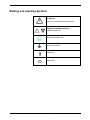
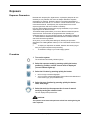
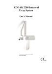
KODAK 2200 Intraoral
X-ray System
User’s Manual
This document is originally written in English.
Manual Name: KODAK 2200 Intraoral X-ray System, User Guide
Document code: SM731
Revision Number: Rev 01
Printed Date: 6/2009
The brand names and logos reproduced in this guide are copyright.
KODAK is a trademark of KODAK used under License.
RVG, Trophy, are registered trademarks of Carestream Health, Inc. All
other names or products referred to in this document are used only for
the purpose of identification and maybe the trademarks or the
registered trademarks of their respective owners.
The RVG technology is the subject of and international patent
registered by Carestream Health, Inc.
Table of Contents
1. Safety and Regulatory Information ...................................................................................1-1
Conventions Used in This Manual .................................................................................................1-1
General Safety Guidelines.............................................................................................................1-1
Warnings and Safety Instructions ..................................................................................................1-2
Marking and Labelling Symbols.....................................................................................................1-4
EEC Regulations ...........................................................................................................................1-5
U.S. Regulations............................................................................................................................1-5
2. System Overview ................................................................................................................2-1
Components ..................................................................................................................................2-1
Wall-Mounted Unit for Irix Replacement ........................................................................................2-3
Label Locations..............................................................................................................................2-4
Ceiling-mounted Unit .....................................................................................................................2-5
Mounted on Mobile Stand (Optional) .............................................................................................2-6
Floor-mounted Unit (Optional) .......................................................................................................2-7
Control Timer Unit..........................................................................................................................2-8
3. Using the System ................................................................................................................3-1
Positioning .....................................................................................................................................3-1
Positioning the patient.......................................................................................................................... 3-1
Positioning the x-ray generator ............................................................................................................ 3-1
Positioning the imaging receptor .......................................................................................................... 3-2
Exposure........................................................................................................................................3-3
Exposure Parameters .......................................................................................................................... 3-3
Procedure ............................................................................................................................................ 3-3
Processing .....................................................................................................................................3-4
Setting Modes................................................................................................................................3-4
Additional Features........................................................................................................................3-5
4. User Mode ............................................................................................................................4-1
Entering the User Mode.................................................................................................................4-1
Changing the Parameters..............................................................................................................4-1
Exiting the User Mode ...................................................................................................................4-1
Parameters ....................................................................................................................................4-1
5. Care and Maintenance ........................................................................................................5-1
General Maintenance ....................................................................................................................5-1
Cleaning............................................................................................................................................... 5-2
Disinfecting .......................................................................................................................................... 5-2
Error Messages .............................................................................................................................5-2
Troubleshooting .............................................................................................................................5-3
6. Technical Specifications ....................................................................................................6-1
Compliance with International Standards ......................................................................................6-1
X-ray Generator .............................................................................................................................6-4
Equipped X-ray Generator.............................................................................................................6-5
Tables of Exposure Times .............................................................................................................6-7
Emitted Doses ...............................................................................................................................6-9
iii
List of Figures
Figure 1: KODAK 2200 Intraoral X-ray System.................................................................................................... 2-1
Figure 2: Side view of KODAK 2200 Intraoral X-ray System .............................................................................. 2-2
Figure 3: KODAK 2200 Intraoral X-ray System:................................................................................................... 2-3
Figure 4: Identification labels on standard mount .............................................................................................. 2-4
Figure 5: Identification labels on Irix replacement mount.................................................................................. 2-4
Figure 6: KODAK 2200 Intraoral X-ray System ceiling-mounted unit ................................................................ 2-5
Figure 7: KODAK 2200 Intraoral X-ray System mounted on mobile stand........................................................ 2-6
Figure 8: KODAK 2200 Intraoral X-ray System floor-mounted unit ................................................................... 2-7
Figure 9: KODAK 2200 Intraoral X-ray System control timer unit...................................................................... 2-8
Figure 10: Patient positioning .............................................................................................................................. 3-1
Figure 11: Paralleling technique (left) and Bisecting technique (right)............................................................. 3-2
Figure 12: Heating and cooling curves for TROPHY TRX 708 tube ................................................................... 6-4
Figure 13: Heating and cooling curves for CEI OCX/65-G tube ......................................................................... 6-4
Figure 14: X-ray generator .................................................................................................................................... 6-5
Figure 15: Heating and cooling curves ................................................................................................................ 6-6
List of Tables
Table 1: Type of Scissors Arms ........................................................................................................................... 2-2
Table 2: Parameters for User Mode...................................................................................................................... 4-1
Table 3: Error Messages ....................................................................................................................................... 5-2
Table 4: Troubleshooting ...................................................................................................................................... 5-3
Table 5: Main characteristics of the x-ray generator .......................................................................................... 6-4
Table 6: Equipped x-ray generator ....................................................................................................................... 6-5
Table 7: Exposure times in seconds for class D-Speed films............................................................................ 6-7
Table 8: Exposure time corrections depending on selected setting ................................................................. 6-7
Table 9: Choice of film type .................................................................................................................................. 6-8
Table 10: Choice of sensor type........................................................................................................................... 6-8
Table 11: Choice of storage phosphor plates ..................................................................................................... 6-8
Table 12: Dose measured at extremity of 20 cm (8 in.) cone.............................................................................. 6-9
Table 13: Exposure surface versus type of collimator used ............................................................................ 6-10
iv
1. Safety and Regulatory Information
The information contained in this manual is based on the experience and
knowledge relating to the subject matter gained by Carestream Health, Inc.
prior to publication. No patent license is granted by this information.
Carestream Health, Inc. reserves the right to change this information without
notice, and makes no warranty, express or implied, with respect to this
information. Carestream Health, Inc. shall not be liable for any loss or
damage, including consequential or special damages, resulting from any use
of this information, even if loss or damage is caused by Carestream Health,
Inc. negligence or other fault.
Conventions Used in This Manual
CAUTION:
Note
Caution points out procedures that you must follow precisely to avoid
damage to the system or any of its components, yourself or others,
loss of data, or corruption of files in software applications.
Notes provide additional information,
such as expanded explanations, hints,
or reminders.
Important
Important highlights critical policy
information that affects how you use
this manual and this product.
General Safety Guidelines
06/2009
•
This product is designed and manufactured to ensure maximum
safety of operation. Operate and maintain it in strict compliance with the
safety precautions and operating instructions contained in this manual.
•
This product meets all the safety requirements applicable to medical
equipment. However, anyone attempting to operate the system must be
fully aware of potential safety hazards.
•
There are no user serviceable parts in this system. The product must
be installed, maintained, and serviced by qualified service personnel
according to procedures and preventive maintenance schedules in the
product service manual. If your product does not operate as expected,
contact your Service Representative.
•
Do not modify this product in whole or in part without prior written
approval from Carestream Health, Inc.
•
The assembly, extensions, adjustments, modifications, and repairs
must be performed by an authorized Service Representative. Your
radiology system must be installed in premises that comply with
applicable standards.
•
Personnel operating and maintaining this system should receive
training and be familiar with all aspects of operation and maintenance.
•
KODAK 2200 Intraoral x-ray system is intended to be used at the
direction of dentists, oral surgeons and orthodontists for x-ray imaging of
the dento-maxillo-facial area.
SM731_K2200_01_en
1-1
•
To ensure safety, read all user manuals carefully before using the
system and observe all Caution, Important, and Note callouts located
throughout the manual.
•
•
Keep this manual with the equipment.
Reading this manual does not qualify you to operate, test, or
calibrate this system.
•
•
Unauthorized personnel are not allowed access to the system.
If the product does not operate properly or fails to respond to the
controls as described in this manual:
•
Follow the safety precautions as specified in this manual.
•
Stop using the equipment and do not make or authorize any changes
to it.
•
Immediately contact your Service Representative, report the
problem, and await further instructions.
•
X-ray systems manufactured by Carestream Health, Inc. comply with
safety standards throughout the world for optimum protection against
radiation risks.
•
Be aware of the product specifications and of system accuracy and
stability limitations. Consider these limitations before making any decision
based on quantitative values. If you have any doubts, consult your Sales
Representative.
CAUTION:
X-rays can be dangerous if used incorrectly. Take precautions even
when following the instructions in this manual.
Use conventional commercially available equipment to protect yourself
and your patients against scattered radiation risks.
•
If you fail to comply with these instructions, Carestream Health, Inc.
will not be responsible for the safety reliability, and characteristics of the
equipment.
Warnings and Safety Instructions
CAUTION:
Do not operate the equipment in the presence of explosive liquids,
vapors, or gases. Do not plug in or turn on the system if hazardous
substances are detected in the environment. If these substances are
detected after the system has been turned on, do not attempt to turn off
the unit or unplug it. Evacuate and ventilate the area before turning off
the system.
DANGER: THIS IS AN ELECTRICAL UNIT. DO NOT EXPOSE IT TO
WATER SPRAY. SUCH ACTION MAY CAUSE AN
ELECTRICAL SHOCK OR A MALFUNCTION OF THE UNIT.
1-2
SM731_K2200_01_en
06/2009
WARNING
The user is responsible for the operation and maintenance of this unit.
This unit must only be operated by legally qualified persons.
The cover of the unit must not be opened by the user.
Inspection and maintenance operations should only be carried out by an
approved technician.
WARNING
This unit must be installed in an x-ray room that complies with current
installation standards. From this location, visual or audio communication
must be maintained with the patient, together with access to the control
interface during exposure.
WARNING
Do not operate the unit if there is the threat of an earthquake.
Following an earthquake, ensure that the unit is operating properly before
using it again.
Failure to observe this precaution may expose patients to hazards.
WARNING
X-ray equipment can be hazardous to patients and the operator if the
exposure safety factors and operating instructions are not observed.
WARNING
Do not place objects within the field of operation of the unit.
WARNING
We recommend that the patient and the operator wear protective lead-lined
aprons, unless other Radiation Protection Protocols apply locally.
Ensure that any parts of the unit that may come into contact with the patient
and the operator have been disinfected after each patient has been exposed
to x-rays.
If the unit develops a fault, turn it off (O) and display a sign that states “Out of
Service.”
WARNING
The operator must ask the patient to refrain from moving during the entire
period of exposure.
In the European Union, this symbol indicates that when the
last user wishes to discard this product, it must be sent to
appropriate facilities for recovery and recycling.
Contact your local sales representative for additional
information on the collection and recovery programs
available for this product.
06/2009
SM731_K2200_01_en
1-3
Marking and Labelling Symbols
ATTENTION:
CONSULT ACCOMPANYING DOCUMENTS
WARNING & IONIZING RADIATION:
IONIZING RADIATION
CHASSIS GROUND STUD.
PROTECTIVE EARTH
POWER ON
POWER OFF
1-4
SM731_K2200_01_en
06/2009
EEC Regulations
The Kodak intraoral x-ray system is a Class II b medical device, which bears
the following mark of conformity:
U.S. Regulations
CAUTION:
U.S. federal law restricts this device to sale by or on the order of a
dentist.
06/2009
SM731_K2200_01_en
1-5
1-6
SM731_K2200_01_en
06/2009
2. System Overview
Components
Figure 1: KODAK 2200 Intraoral X-ray System
1. High-frequency x-ray generator
•
Transformer and associated electronics, and an oil-bathed x-ray tube
•
Beam-limiting device
•
•
Radiation diameter – 6 cm (2 3/8 in.)
•
Distance from x-ray tube focal spot to skin – 20 cm (7 7/8 in.)
Angle scale and handle to facilitate positioning
2. Wall framework
•
Contains the high-frequency generator’s control electronics
3. Control timer unit
06/2009
•
Anatomical selection and display of parameters (exposure time,
emitted dose)
•
Self-test of the microprocessor each time the unit is activated
•
Alarm during incorrect operation
•
2 pre-set modes or manual exposure settings
SM731_K2200_01_en
2-1
4. Scissor arm
•
Wall-mounted with a choice of extensions
Figure 2: Side view of KODAK 2200 Intraoral X-ray System
Extension
R
Span A
CG 645
47,0 cm
(18.5 in.)
170.0 cm
(66 15/16 in.)
CG 646
64.8 cm
(25.5 in.)
188.0 cm
(74 in.)
CG 648
82.5 cm
(32.5 in.)
205.0 cm
(80 11/16 in.)
Table 1: Type of Scissors Arms
5. On/off switch
•
Contains built-in light
6. Rectangular collimator (optional)
•
Different sizes adapted to films and RVG sensors
Additional options
2-2
•
Separate control timer
•
Separate exposure switch (if the control panel is attached to the wall
framework)
•
Wall-mounted unit for Irix replacement
•
Ceiling-mounted unit
•
Floor-mounted unit
•
Unit mounted on mobile stand
SM731_K2200_01_en
06/2009
Wall-Mounted Unit for Irix Replacement
Figure 3: KODAK 2200 Intraoral X-ray System:
Replacement of Irix System
1.
2.
3.
4.
5.
6.
7.
06/2009
High-frequency x-ray generator
Wall framework
Control timer unit
Separate exposure switch
Scissor arm
Rectangular collimator
On/off switch with built-in light
SM731_K2200_01_en
2-3
Label Locations
Figure 4: Identification labels on standard mount
Figure 5: Identification labels on Irix replacement mount
2-4
SM731_K2200_01_en
06/2009
Ceiling-mounted Unit
Figure 6: KODAK 2200 Intraoral X-ray System ceiling-mounted unit
1. High-frequency x-ray generator
2. Ceiling-mounted unit containing the high-frequency x-ray
generator’s control electronics
3. Separate timer/control unit for the x-ray generator
4. Scissor arm
5. On/off switch with built-in light
6. Rectangular collimator
06/2009
SM731_K2200_01_en
2-5
Mounted on Mobile Stand (Optional)
Figure 7: KODAK 2200 Intraoral X-ray System mounted on mobile stand
1. High-frequency x-ray generator
2. Mobile stand containing the high-frequency x-ray generator’s
control electronics
3. Timer/control unit for the x-ray generator
4. Scissor arm
5. On/off switch with built-in light
6. Rectangular collimator
7. Handle
8. Foot brake
2-6
SM731_K2200_01_en
06/2009
Floor-mounted Unit (Optional)
Figure 8: KODAK 2200 Intraoral X-ray System floor-mounted unit
1. High-frequency x-ray generator
2. Floor column containing the high-frequency x-ray generator’s
control electronics
3. Timer/control unit for the x-ray generator
4. Scissor arm
5. On/off switch with built-in light
6. Rectangular collimator
7. Extension Arm
06/2009
SM731_K2200_01_en
2-7
Control Timer Unit
Figure 9: KODAK 2200 Intraoral X-ray System control timer unit
1. Display
2. Exposure time - emitted dose selection
3. X-ray exposure button
4. X-ray emission control light
5. Cooling indicator
6. Child/Adult/Large selector
7. kV selector
8. Receptor selector (2 pre-set modes, 1 manual mode)
9. Teeth selector
10. Bitewing selector
11. Occlusal selector
12. Selection knob:
•
Pre-set mode: Rotate the knob to select tooth
•
Manual mode: Rotate the knob to select the exposure time
•
Press the knob quickly to display the latest measure dose emitted
13. Warning: Ionizing radiation
2-8
SM731_K2200_01_en
06/2009
3. Using the System
Every dental specialist would like to produce high-quality intraoral
radiographs that reveal maximum detail with the minimum dose to the
patient, show teeth and anatomic structures accurately with a minimum of
distortion or magnification, and have optimal density and contrast to
maximize their use for the detection of dental diseases.
To obtain high-quality intraoral radiography with maximum details, take extra
care in all three steps of the radiography process: positioning the patient, the
x-ray generator, and the imaging system; exposing the film or the sensor;
and processing the film.
Positioning
Positioning the patient
Seat the patient with the sagittal plane vertical.
•
For radiography of the upper maxillary, the Frankfort plane (nose-ear
plane) must be horizontal.
•
For radiography of the lower maxillary, the occlusal plane must be
horizontal.
Figure 10: Patient positioning
Positioning the x-ray generator
The scissor arm allows you to accurately position the generator for any type
of exposure. The beam-limiting device maintains a distance of at least 20 cm
(8 in.) between the focal spot and the skin, which allows you to use either the
paralleling technique or the bisecting technique.
Paralleling technique
The positioning tool used in the paralleling technique allows you to align the
beam and the receptor. An adapted collimator reduces the dosage by limiting
surface exposure.
Bisecting technique
When using the bisecting technique, do not use a rectangular collimator. This
limits the risk of misaligning the x-ray beam and the image receptor.
06/2009
SM731_K2200_01_en
3-1
Figure 11: Paralleling technique (left) and Bisecting technique (right)
Positioning the imaging receptor
Using the KODAK 2200 Intraoral X-ray System, you may create an x-ray
image on one of three different types of imaging receptors:
•
•
Conventional silver halide films, such as KODAK INSIGHT or
KODAK ULTRA-SPEED dental films.
Digital sensors, such as KODAK RVG sensor.
•
Phosphor plate, such as KODAK Imaging plates.
Properly placing the receptor is critical. Check your dental radiography text
for information about proper placement of the imaging receptor.
Improperly positioning the film or sensor results in errors on the radiograph,
such as distorted teeth and roots, elongation, magnification, and/or
overlapping contacts. The paralleling technique generally reduces the risk of
such errors. However, if you improperly position the system, angulation
errors can occur (angulation of the receptor to the tooth itself).
If the exit pattern of the beam is not aligned with the imaging receptor, then
part of the radiograph will not be exposed to radiation and the final
radiograph will have some clear (unexposed) areas. This defect is called
“cone cuts”.
The imaging receptor is marked to indicate the tube side. If the orientation is
not correct, the resulting radiograph is lighter and may show artifacts, such
as foil pattern or sensor cable.
3-2
SM731_K2200_01_en
06/2009
Exposure
Exposure Parameters
Because each receptor (film, digital sensor, or phosphor plate) has its own
sensitivity to x-ray radiation, the choice of receptor affects the exposure
parameters. For instance, sensitivity class for conventional dental films is
characterized with a letter D, E, or F where F is more sensitive than E, and E
more sensitive than D. Consequently, the required dose for the correct
exposure goes down with each increase in sensitivity.
Like film, different digital sensors have varying sensitivities, so you need to
adjust exposure for sensors as well.
This KODAK 2200 system allows you to use 2 different modes with pre-set
exposure times. These modes are programmed when installing the
equipment based on your local imaging systems, as indicated in Tables 9 to
11. These tables are established under manufacturer’s standard conditions
and should be used as guidelines.
At any time, you can modify these settings by following the procedure
described in the "Setting Modes" below (or in the "User Mode" section of this
guide):
•
To adjust your exposures as needed, based on the results you get
from your system’s exposure and processing.
•
To actualize a change in your local imaging system.
Procedure
1. Turn on the system.
The on/off button and Ready indicator light up.
2. Select the exposure mode by pressing quickly the button,
position by position, until the correct mode is displayed
(correct indicator lights up).
3. Select the kV value by pressing quickly the button:
•
60 kV for high-contrast radiographs.
•
70 kV for lower-contrast radiographs that provide a wider latitude and
more levels of grey (for periodontal work).
4. Select the type of patient by pressing quickly the button:
child, adult, large.
5. Select the tooth (or the exposure time in case of manual
mode) by turning the selection knob.
The unit displays the exposure time.
CAUTION:
The operator must instruct the patient to refrain from moving during the
entire exposure.
06/2009
SM731_K2200_01_en
3-3
6. Acquire the image.
•
Press the x-ray exposure button on the control timer unit (or on the
remote exposure switch). The x-ray emission indicator lights up and
an audible signal is emitted.
•
Keep pressing until the x-ray emission light goes out and the audible
signal stops.
CAUTION:
If you stop pressing the control key before the exposure ends, a
manipulator alarm is activated. It indicates that the x-ray emission was
interrupted prematurely and that there is a risk of underexposure.
7. Read the emitted dose.
Quickly press the selection knob. The “mGy” indicator lights up and the
dose in mGy is displayed. Section 6 provides a table with emitted dosage
based on exposure times (see Table 12).
Processing
When using conventional film, process the film according to manufacturer’s
instructions. Develop the film under safelight conditions in an automatic
processor or manually.
If you use an automatic processor, refer to the processor’s manual. Be sure
to maintain the mechanically and keep the solutions replenished.
If you develop film manually, follow precisely the manufacturer’s
recommendations for solution preparation, development time, and solution
temperature. Any deviation from the manufacturer’s recommendations (such
as a solution that is too concentrated or diluted, too hot or cold, or if film is
processed for the wrong amount of time), will adversely affect the quality of
the final radiograph.
Setting Modes
1. Select the mode to be set by pressing and holding the selection
button for at least 3 seconds, as many time as necessary to get the
desired LED lighted.
2. Press and hold simultaneously for at least 3 seconds the selection
button and the knob until the display blinks. The current setting is
displayed.
3. Modify the setting by rotating the knob until the new setting is
displayed (refer to the setting table as indicated in Tables 9 to 11).
4. Validate your choice by pressing and holding the knob until the
message “copy” is displayed or abort by pressing shortly the knob.
3-4
SM731_K2200_01_en
06/2009
Additional Features
•
KODAK 2200 Intraoral X-ray System uses a high-frequency
technology that has several advantages:
•
Shorter exposure times, reducing the risk of blur due to movement of
the patient or film during exposure.
•
Reduction in x-ray dose to patients because the KODAK 2200
System emits fewer soft rays absorbed by patients that do not
contribute to the radiological picture.
•
•
Choice of high voltage between 60 kV and 70 kV:
•
60 kV for high-contrast radiographs giving a clear image of the
endodontal instruments or clearly displaying tooth decay.
•
70 kV for better reproduction of levels of grey (soft tissue), useful for
periodontal work.
A thermal safety system prevents the generator from overheating in
case of intensive use. This system can prohibit any exposure as long as
the generator did not cool. The error message I 01 appears on the
display unit, a red LED lights up on the control unit, and an audible signal
is emitted until the cooling period is over.
CAUTION:
Do not turn off the system. If you turn off power, the microprocessor
does not calculate the cooling time, and for safety reasons considers
that the system has not gone into the cooling cycle.
06/2009
•
While the exposure is taken, the exposure time counts off on the
control unit display.
If the exposure is interrupted (such as by releasing the key), the audible
and visible manipulator alarm is activated and the remaining exposure
time is displayed. This information makes it easier to decide whether to
develop the film or to start another exposure (if the remaining time is
short, you may develop the film).
To stop the manipulator alarm, press the selection knob.
•
A self-test automatically activates when you turn on the unit.
The self-test checks the display, the alarm lights and all the systems.
If the self-test detects a problem, an error code is displayed.
When the test is completed, a short beep sounds and the display shows
the firmware version and the total number of exposures (divided by 10)
taken by this unit since it was installed.
SM731_K2200_01_en
3-5
3-6
SM731_K2200_01_en
06/2009
4. User Mode
The User Mode allows you to select the settings to be used for the different
pre-set modes. It also allows you to validate specific local requirements for
some countries.
Entering the User Mode
1. Turn on the system.
The self-test is activated. At the end of the self-test, the software
information is displayed (for example, F718 1.00).
2. Quickly press the selection knob on the control timer to enter the menu.
You have access to the menu, when “USER” is displayed. The display
intermittently shows the first parameter (P 03) and the setting (for
example, “0”).
3. To change from one parameter to another, turn the selection knob step
by step in any direction.
Changing the Parameters
To change the parameters:
1. Press and hold the selection knob at least 3 seconds until the display
shows “EDIT” and you hear a sound.
The parameter value starts blinking.
2. Turn the selection knob to change the parameter value.
•
To validate your choice, press and hold the selection knob at least 3
seconds until “COPY” is displayed and a noise sounds.
•
To keep the initial value, press the selection knob briefly until “Abor”
is displayed. The system returns to the parameters/programs mode.
Exiting the User Mode
To exit the User mode, press the selection knob briefly.
“Quit” is displayed before the system returns to the operational mode.
Parameters
N°
Parameters
Choice
P 03
Country of installation
0 for all countries except those
having specific local
requirements. Refer to
Installation Manual
P 4.1
Film mode setting
S 01 to S 16
P 4.2
Digital mode setting
S 01 to S 16
P 05
Tube seasoning procedure
Changes OFF to ON. Refer to
Installation Manual
P 06
Show mode
ON to disable X-ray emission
OFF (default) to enable X-ray
emission
Table 2: Parameters for User Mode
06/2009
SM731_K2200_01_en
4-1
4-2
SM731_K2200_01_en
06/2009
5. Care and Maintenance
General Maintenance
To make sure that the system functions correctly, you must have it serviced
annually by an authorized technician. In addition, every three months inspect
the equipment and make sure of the following:
Generator
•
The certification label is legible.
•
There are no oil leaks.
Mechanical support
•
The wall framework is securely attached to the wall.
•
All the labels are legible.
•
The scissor arm is stable in all positions.
Control unit and electrical installation
•
•
The symbols are legible.
The control unit cable and the power supply cable are in good
condition.
•
The ground is correctly installed.
•
The radiology control key returns to its initial position after use.
Functioning
•
The audible signal is audible and the x-ray emission light is visible
when you make an exposure (manual mode, 70kV, 0.1 sec.).
•
The message “E 01”, which means Operator Error, is displayed when
you make an exposure (manual mode, 70kV, 1.0 sec.) and release the
control button before the exposure time has elapsed.
Timer self-test
•
Turn on the system to activate the self-test.
•
The test starts with a simultaneous test of the display and alarm
lights.
•
The unit proceeds to the systems test. At the end of this test,
indicated by a short beep, the firmware version and the total number
of exposures (divided by 10) made by the machine since installation
is displayed.
•
If the test is not successful, an Error code is displayed on the display.
Important
If the result of any of these checks is
not satisfactory, discontinue using the
equipment and contact an authorized
technician.
06/2009
SM731_K2200_01_en
5-1
Cleaning
Clean the outside of the system with a damp paper towel or soft cloth using
an alcohol-based, non-corrosive cleaner.
Disinfecting
If necessary, wipe off surfaces with disinfectant.
CAUTION:
•
Do not allow liquids to drip into the system.
•
Do not spray cleaner or disinfectant directly onto the machine.
•
Protect the system from contamination using barriers available
from dental distributors.
•
Follow the manufacturer’s safety recommendations when using
the cleaner or disinfectant.
Error Messages
Error Message
I 01 and a red LED
lights up on the
control unit
Cause
Cooling cycle: this message can appear
during a period of intensive use.
How to cancel
Do not turn off the system. The error
message will disappear when the
system returns to a satisfactory
temperature.
CAUTION:
If you turn off power to the system, the microprocessor does not calculate the cooling time, and for
safety reasons considers that the system has not gone into the cooling cycle.
I 02
Request for a x-ray tube seasoning
Refer to Installation Manual
E 01
plus audible alarm
Release of the radiography control button
before the end of the exposure. The display
shows the remaining exposure time (Based
on this time, decide whether to develop the
film or make another exposure).
Press the selector knob to stop the
alarm.
E 02
The radiography control was activated while
the unit was being powered on.
E 03-E 04
Problems with the exposure time control.
E 10 to E 18
kV voltage error.
E 20 to E 24
Filament voltage error.
E30
Problem with voltage to main power supply
or to chemical capacitor.
E 40 to E 46
System error (problems with the
microprocessor on the power board).
E 50 to E 54
Problems with the I2C bus (the connection
between the control panel and the power
board).
Turn off the system and restart. If the
problem persists, call a qualified service
technician and discontinue using the
equipment.
Table 3: Error Messages
5-2
SM731_K2200_01_en
06/2009
Troubleshooting
Problem
Nothing lights up
Control unit doesn’t light
up
No x-ray emission
X-ray emission works, but
exposure is too light or
completely white.
X-ray emission works, but
exposure is too dark.
Cause
Solution
Unit is disconnected.
Connect the unit.
Fuse F1 is burned out or defective.
Replace the fuse.
Circuit breaker is off.
Turn on the circuit breaker.
Control unit is disconnected.
Connect the control unit.
Fuse F1 is burned out or defective.
Replace the fuse.
Control unit is defective.
Call a qualified service technician.
Generator is cooling.
Wait for the I 01 message and the red
LED on the control unit to disappear.
Radiology control key is defective.
Call a qualified service technician.
Wrong exposure pre-set program is
being used.
Change the pre-set program (refer to the
User Mode section).
Generator is positioned incorrectly.
Adjust the position of the generator.
Exposure time is too short.
Increase the exposure time.
Development time is too short.
Increase the development time (refer to
the development instructions).
Developer is too cold.
Heat the developer.
Developer is too old or diluted.
Replace with fresh developer.
Pre-set mode is incorrectly selected.
Verify your exposure settings (refer to
the exposure procedure).
Receptor is facing the wrong way.
Reposition the receptor.
Unit was incorrectly installed.
Call a qualified service technician.
Wrong exposure pre-set program is
being used.
Change the pre-set program (refer to the
User Mode section).
Exposure time is too long.
Decrease the exposure time.
Development time is too long.
Decrease the development time (refer to
the development instructions).
Developer is too hot.
Cool the developer.
Developer is too concentrated.
Adjust the concentration or replace the
developer.
Pre-set mode is incorrectly selected.
Verify your exposure settings (refer to
the exposure procedure).
Table 4: Troubleshooting
06/2009
SM731_K2200_01_en
5-3
6. Technical Specifications
Compliance with International Standards
Manufactured by:
Trophy
A subsidiary of Carestream Health, Inc.
4, rue F. Pelloutier - Croissy-Beaubourg
77435 Marne-la Vallée Cedex 2
France
For :
Carestrem Health, Inc.
150 Veronal Street
Rochester,
New York – USA 14608
Models
KODAK 2200
Compliance with International Regulations
• Medical Device directives 93/42/European Economic Community (EEC),
Class II b
• ElectroMagnetic Compatibility (EMC) directive 89/336/EEC
• FDA Center for Devices & Radiological Health (CDRH-21-CFr title 21 subchapter J) (USA)
• Radiation Emitting Devices Act – C34 (Canada)
• Medical Devices Regulations (Canada)
Compliance with European and International Standards
• EN 60601-1 / IEC 60601-1
• EN 60601-1-3 / IEC 60601-1-3
• EN 60601-2-7 / IEC 60601-2-7
• EN 60601-2-28 / IEC 60601-2-28
• EN 60601-1-4 / IEC 60601-1-4
• CSA 601.1
• UL60601.1
• EN ISO 14971
Electric power supply
(during exposure)
• 230–240 V AC (± 10%), 50/60 Hz, 5 A, apparent resistance 0.5 Ω
• 100–110–130 V AC (± 10%), 50/60 Hz, 12 A, apparent resistance 0.2 Ω
Electric power supply
(no exposure)
• 230–240 V AC (± 10%), 50/60 Hz, 220 mA
• 100–110–130 V AC (± 10%), 50/60 Hz, 220 mA
06/2009
SM731_K2200_01_en
6-1
Rated high voltage and maximum corresponding current
• 70 kV, 7 mA
Current/voltage combinations for a maximum output power of:
• 490 W, 70 kV / 7 mA
Rated power for exposure time of 0.1 sec.
• 490 W
Rate of use
• At 70 kV, 7 mA and 0.1 sec. and at the maximum tank temperature: one
exposure every 8 sec.
Minimum value of the current/time product in the range of
conformity
• 0.07 mAs at 7 Ma
Selection of parameters
• 70 kV / 7 mA and 60 kV / 7 mA
Area of conformity to IEC standard 60601-2-7
• Reproducibility of the emitted radiation: conform
• Linearity of the emitted radiation: conform
• Precision in radiography: conform
Measurement conditions
• kV: Indirect measurement using a kV peakmeter
• mAs: Direct measurement in the circuit using a mAs-meter
• Exposure time: Indirect measurement on the kV signal at 75% of the
peak value
Type of protection against
electric shock
Class 1 equipment
Degree of protection against
electric shock
Type B
Protection against harmful
ingress of water
Ordinary equipment
Operation mode
Continuous operation with
intermittent loading
Flammable anesthetics
6-2
SM731_K2200_01_en
Not suitable for use in presence of
flammable anesthetics or a
mixture of flammable anesthetics
with air or oxygen or nitrous oxide
06/2009
Classification in Accordance with EN/IEC 60601-1-2
Group I, class B
Ambient Operating Conditions
•
Temperatures: 5 to 35° C
•
Relative humidity: 30 to 85%
•
Atmospheric pressure: 700 to 1060 hpa
Storage Conditions
•
Temperatures: -10 to 60° C
•
Relative humidity: 10 to 95%
•
Atmospheric pressure: 700 to 1060 hpa
Transport Conditions
•
Temperatures: -10 to 60° C
•
Relative humidity: 10 to 95%
•
Atmospheric pressure: 700 to 1060 hpa
Dimensions and weight
Control Unit
16 x 9 x 4 cm
0.4 kg
(6.3 x 3.5 x 1.6 in.)
(0.9 lb)
Wall framework
51.4 x 18.9 x 10.8 cm
4.1 kg
(standard)
(20.2 x 7.4 x 4.3 in.)
(9.0 lb)
Wall framework
42.0 x 30.9 x 9.8 cm
4.1 kg
(Irix replacement)
(16.5 x 12.2 x 3.9 in.)
(9.0 lb)
X-ray emitting unit
43.8 x 22.6 x 12 cm
4.3 kg
(17.2 x 8.9 x 4.7 in.)
(9.5 lb)
87.3 x 13.3 x 6.3 cm
9 kg
(34.4 x 5.2 x 2.5 in.)
(19.8 lb)
90 x 60 x 110 cm
40 kg
(35.4 x 23.6 x 43.3 in.)
(88.2 lb)
24 x 23 x 90 cm
20 kg
(9.4 x 9.1 x 35.4 in.)
(44.2 lb)
50 x 50 x 154 cm
12.8 kg
(19.7 x 19.7 x 60.6 in.)
(28.2 lb)
Scissor arm
Mobile stand (optional)
Floor column (optional)
Ceiling column
Scissor arm
• Equipped with gas jack specially designed for this application; proven to
function correctly after more than 400,000 cycles.
06/2009
SM731_K2200_01_en
6-3
X-ray Generator
TROPHY type TRX 708
CEI type OCX/65-G
Rated high voltage
70 kV
70 kV
Rated anodic power
490 W
490 W
Maximum heat
accumulated in the anode
8,700 J
10.000 J
Rated value of focal spot
(IEC 60336/1993)
0,7 mm (0.027 in.)
0.7 mm (0.027 in.)
Target materials
Tungsten
Tungsten
Target slope
19°
19°
Filtration due to fixed
materials
0,6 mm (0.023 in.) eq. Al
0,6 mm (0.023 in.) eq. Al
Table 5: Main characteristics of the x-ray generator
Figure 12: Heating and cooling curves for TROPHY TRX 708 tube
Figure 13: Heating and cooling curves for CEI OCX/65-G tube
6-4
SM731_K2200_01_en
06/2009
Equipped X-ray Generator
Parameters
Features
IEC standard 60601-2-28 (1993)
Conform
Type of protection against electric shocks
Class 1
Degree of protection against electric shocks
Type B
Rated value of inherent filtration
1.5 mm (0.059 in.) eq. Al
Rated value of additional filtration
1.0 mm (0.039 in.) eq. Al
Rated value of total filtration
2.5 mm (0.098 in.) eq. Al
Beam-limiting cone, focal spot/skin distance
20 cm (7 7/8 in.)
Maximum accumulated heat.
32,500 J
Maximum continuous thermal dissipation
7W
Amount of leaking radiation at maximum rate
during one hour of use
< 0.25 mGy
Maximum field of symmetrical radiation
6 cm (2 3/8 in.) diameter
Position and tolerance of the focal point on
the reference axis
0 mm +/- 0.5 mm (0.020 in.)
Table 6: Equipped x-ray generator
Figure 14: X-ray generator
a) Reference axis
b) Target angle
c) Focal point
06/2009
SM731_K2200_01_en
6-5
Figure 15: Heating and cooling curves
of the KODAK 2200 system tube head
6-6
SM731_K2200_01_en
06/2009
Tables of Exposure Times
The following exposure timetables were established with a unit equipped with
a standard cone with a focus-to-skin distance of 20 cm (8 inches).
70kV – 7mA
Cone 20 cm (8 in.)
Maxillary
Child
Adult
Large
Incisor / Bicuspid
0.119
0.180
0.227
Premolar
0.152
0.230
Molar
0.178
Mandibular
Incisor / Bicuspid
60kV – 7mA
Cone 20 cm (8 in.)
Child
Adult
Large
Incisor / Bicuspid
0.238
0.360
0.454
0.290
Premolar
0.304
0.460
0.580
0.270
0.340
Molar
0.356
0.540
0.680
Child
Adult
Large
Child
Adult
Large
0.099
0.150
0.189
Incisor / Bicuspid
0.198
0.300
0.378
Premolar
0.106
0.160
0.202
Premolar
0.211
0.320
0.403
Molar
0.119
0.180
0.227
Molar
0.238
0.360
0.454
Bitewing
Maxillary
Mandibular
Child
Adult
Large
Child
Adult
Large
Anterior
0.099
0.150
0.189
Anterior
0.198
0.300
0.378
Posterior
0.119
0.180
0.227
Posterior
0.238
0.360
0.454
Child
Adult
Large
Child
Adult
Large
0.205
0.310
0.391
0.409
0.620
0.781
Occlusal
Bitewing
Occlusal
Table 7: Exposure times in seconds for class D-Speed films
Setting
Correction
Coefficient
S 01
- 92 %
0.08
S 02
- 90 %
0.10
S 03
- 88 %
0.125
S 04
- 84 %
0.16
S 05
- 80 %
0.20
S 06
- 75 %
0.25
S 07
- 68 %
0.31
S 08
- 60 %
0.40
S 09
- 50 %
0.50
S 10
- 37 %
0.63
S 11
- 21 %
0.79
S 12
0%
1.00
S 13
+ 26 %
1.26
S 14
+ 59 %
1.59
S 15
+ 100 %
2.00
S 16
+ 152%
2.52
Table 8: Exposure time corrections depending on selected setting
06/2009
SM731_K2200_01_en
6-7
Brand
Name
Setting
Kodak
Insight
S 08
Kodak
E-speed
S 09
Kodak
Ultra-speed
S 12
Kodak
D-speed
S 12
Other films
Speed class F
S 08 or S 09
Other films
Speed class E
S 09 or S 10
Other films
Speed class D
S 12 or S 13
Table 9: Choice of film type
Brand
Name
Setting
Kodak
Kodak 5100
S 08
Kodak
RVG 5000
S 08
Trophy
RVG Access
S 08
Kodak
Kodak 6100 size 1 & 2
S 07
Kodak
RVG 6000
S 07
Trophy
RVG Ultimate
S 07
Trophy
RVG Reference Hi Resol mode
S 07
Trophy
RVGui Hi Resol mode
S 07
Trophy
Kodak RVG 6100 size 0
S 05
Trophy
RVG THD
S 05
Trophy
RVG Reference Hi Sensi mode
S 02
Trophy
RVGui Hi Sensi mode
S 02
Other brands
Adjust your sensor type
*
Table 10: Choice of sensor type
Brand
Name
Kodak
CR 7400
Other brands
Adjust the phosphor plate type.
Setting
S 12
*
Table 11: Choice of storage phosphor plates
6-8
SM731_K2200_01_en
06/2009
Emitted Doses
To obtain the dose in mGy.cm2, multiply values in the tables by the exposed
surface. The exposed surface depends on the collimator that is used and is
indicated in Table 13.
70kV – 7mA
60kV – 7mA
t(s)
D
mGy
t(s)
D
mgY
t(s)
D
mGy
t(s)
D
mgY
t(s)
D
mGy
t(s)
D
mgY
t(s)
D
mGy
t(s)
D
mgY
0.010
0.09
0.260
2.22
0.510
4.36
0.760
6.49
0.010
0.06
0.260
1.58
0.520
3.17
1.020
6.21
0.020
0.17
0.270
2.31
0.520
4.44
0.770
6.58
0.020
0.12
0.270
1.64
0.540
3.29
1.040
6.33
0.030
0.26
0.280
2.39
0.530
4.53
0.780
6.66
0.030
0.18
0.280
1.71
0.560
3.41
1.060
6.46
0.040
0.34
0.290
2.48
0.540
4.61
0.790
6.75
0.040
0.24
0.290
1.77
0.570
3.53
1.080
6.58
0.050
0.43
0.300
2.56
0.550
4.70
0.800
6.83
0.050
0.30
0.300
1.83
0.600
3.65
1.100
6.70
0.060
0.51
0.310
2.65
0.560
4.78
0.810
6.92
0.060
0.37
0.310
1.89
0.620
3.78
1.120
6.82
0.070
0.60
0.320
2.73
0.570
4.87
0.820
7.00
0.070
0.43
0.320
1.95
0.640
3.90
1.140
6.94
0.080
0.68
0.330
2.82
0.580
4.95
0.830
7.09
0.080
0.49
0.330
2.01
0.660
4.02
1.160
7.06
0.090
0.77
0.340
2.90
0.590
5.04
0.840
7.17
0.090
0.55
0.340
2.07
0.680
4.14
1.180
7.19
0.100
0.85
0.350
2.99
0.600
5.12
0.850
7.26
0.100
0.61
0.350
2.13
0.700
4.26
1.200
7.31
0.110
0.94
0.360
3.07
0.610
5.21
0.860
7.34
0.110
0.67
0.360
2.19
0.720
4.38
1.220
7.43
0.120
1.02
0.370
3.16
0.620
5.29
0.870
7.43
0.120
0.73
0.370
2.25
0.740
4.51
1.240
7.55
0.130
1.11
0.380
3.25
0.630
5.38
0.880
7.52
0.130
0.79
0.380
2.31
0.760
4.63
1.260
7.67
0.140
1.20
0.390
3.33
0.640
5.47
0.890
7.60
0.140
0.85
0.390
2.38
0.780
4.75
1.280
7.80
0.150
1.28
0.400
3.42
0.650
5.55
0.900
7.69
0.150
0.91
0.400
2.44
0.800
4.87
1.300
7.92
0.160
1.37
0.410
3.50
0.660
5.64
0.910
7.77
0.160
0.97
0.410
2.50
0.820
4.99
1.320
8.04
0.170
1.45
0.420
3.59
0.670
5.72
0.920
7.86
0.170
1.04
0.420
2.56
0.840
5.12
1.340
8.16
0.180
1.54
0.430
3.67
0.680
5.81
0.930
7.94
0.180
1.10
0.430
2.62
0.860
5.24
1.360
8.28
0.190
1.62
0.440
3.76
0.690
5.89
0.940
8.03
0.190
1.16
0.440
2.68
0.880
5.36
1.380
8.40
0.200
1.71
0.450
3.84
0.700
5.98
0.950
8.11
0.200
1.22
0.450
2.74
0.900
5.48
1.400
8.53
0.210
1.79
0.460
3.93
0.710
6.06
0.960
8.20
0.210
1.28
0.460
2.80
0.920
5.60
1.420
8.65
0.220
1.88
0.470
4.01
0.720
6.15
0.970
8.28
0.220
1.34
0.470
2.86
0.940
5.72
1.440
8.77
0.230
1.96
0.480
4.10
0.730
6.23
0.980
8.37
0.230
1.40
0.480
2.92
0.960
5.85
1.460
8.89
0.240
2.05
0.490
4.18
0.740
6.32
0.990
8.45
0.240
1.46
0.490
2.98
0.980
5.97
1.480
9.01
0.250
2.14
0.500
4.27
0.750
6.41
1.000
8.54
0.250
1.52
0.500
3.05
1.000
6.09
1.500
9.14
Table 12: Dose measured at extremity of 20 cm (8 in.) cone
Note
Dose accuracy: +/- 30% (mGy)
06/2009
SM731_K2200_01_en
6-9
Collimator
type
Format
(mm)
Used with
digital
sensor
Used
with film
Exposure
surface
(cm2)
A
19 x 24
Size 0
-
4.6
B
23 x 35
Size 1
Size 0 22 x 35
8.3
C
31 x 39
Size 2
Size 1 24 x 40
Size 2 31 x 41
12.1
Standard
cone
60 mm
diameter
-
Size 3 27 x 54
Size 4 57 x 76
28.3
Table 13: Exposure surface versus type of collimator used
6-10
SM731_K2200_01_en
06/2009
06/2009
SM731_K2200_01_en
6-11
© Carestream Health, Inc., 2009
The Kodak trade mark and trade dress are used under license from
Eastman Kodak Company
SM731-1 06/09
Trophy
A subsidiary of Carestream Health, Inc.
4 rue F. Pelloutier
Croissy-Beaubourg
77435 Marne la Vallée Cedex 2 (France)
+33 1 64 80 85 00
6-12
SM731_K2200_01_en
06/2009