1
The rube Framework for Personalized
3-D Software Visualization
John F. Hopkins and Paul A. Fishwick
Department of Computer and Information Science
University of Florida, Gainesville, FL, USA
2
The rube Framework for Personalized 3-D Software Visualization
Introduction
Abstract
In this chapter, we discuss a software modeling and visualization framework
called rube†. This framework facilitates the creation of three-dimensional (3-D)
software visualizations that integrate both static software architecture and dynamic real-time operation. A unique aspect of rube is that it does not tie developers down to a set of predefined symbols, objects, or metaphors in their
visualizations. Consequently, users have the freedom to develop their own representations. The rube framework’s general approach to software modeling and
representation are discussed. Next, a simple example is developed according to
rube’s systematic modeling and visualization process. Lastly, benefits of the
framework and future directions are discussed.
Background
Modeling plays an important role in many computing tasks, including software
engineering and software visualization (SV). The first two phases of the modeling process involve system understanding and model representation. In the current context, a system is any real-world (e.g., ecosystem) or abstract (e.g.,
database) entity, and a model represents the discrete objects and interactions
between objects in the system. If readers will indulge us, we consider the terms
software, program, and model to be more or less conceptually equivalent unless
otherwise noted for the purpose of discourse in this chapter. Likewise, we consider the terms software developer, programmer, and modeler to be more or less
conceptually equivalent unless otherwise noted.
Modelers come to understand, predict, and analyze a system based on the
models that they construct for it. The model represents a key medium that links
modelers to the phenomena. Thus, the model’s representation plays an important
role as an interface to its users. Although historically there has been a rich variety of textual and diagrammatic approaches to model representation, there has
been little systematic accommodation of personal preference in these approaches.
Our culture is driven in part by economy of labor and materials, and personalization is held back primarily for these economic reasons. However, today’s
economy is at a stage where personalization has become more feasible and some
trends in personalization are developing in both media and human-computer
interfaces. For our immediate purposes, we do not draw a distinction between
customization and personalization, treating both as facets of aesthetic choice.
†
rube is a trademark of Paul A. Fishwick and the University of Florida.
3
J. F. Hopkins and P. A. Fishwick
An example of personalization in human-computer interfaces is the current proliferation of customized skinz in window-based graphical user interfaces (GUIs).
The renewed focus on accommodating the individual in media and user interfaces suggests a corresponding accommodation of personal preference in model
representation and by extension, 3-D SV.
There may be some advantage to be gained from personalization in 3-D
visualization. To illustrate, a frequent occurrence during the development process is that one or more abstract data types or functions are created. If a developer finds value in 3-D visualization and would like to visualize an abstract
function such as a sorter, he or she may arbitrarily decide to visualize it as a
green pyramid. Instead, it may be possible to create a more elaborate visualization for the sorter. For example, the developer might be able to visualize the
sorter as an animated person who is sorting boxes. If the developer uses the
animated sorting person, he or she has made an analogy between the abstract
sorter and the concrete, real-world person. If the sorter is visualized in this fashion, there is no need to memorize the previous mapping of the green pyramid to
the sorter. The visualization of the person and the analogy introduced now provide this mapping implicitly. In effect, the visualization provides a semantic cue
as to the object’s function. This sort of visualization, then, may serve as a form
of implicit documentation. It would be difficult to support the argument that the
green pyramid visualization is preferable to the animated sorting person on
grounds other than the additional effort it would take to produce the animated
person. Finally, the extra effort required to produce a personalized 3-D visualization should decrease to a minimal level with time and advances in technology,
so that a cost/benefit analysis should eventually become favorable.
There is some empirical evidence that shows the value of self-construction
in visualization. For example, the use of metaphor in diagrams has been shown
to provide some mnemonic assistance, which appears to be greatest when the
user of the diagram constructs his or her own metaphor [1]. In addition, it has
been empirically established that the process of actively constructing one’s own
visual representations is more beneficial than passively viewing someone else’s
visual representations [2].
Fishwick [3, 4] has been developing a modeling framework called rube in
which users develop both static and dynamic 3-D model visualizations in parallel with other modeling efforts. What sets rube apart from similar work is that
these visualizations can be highly customized by the user. This chapter discusses rube’s approach to modeling and representation. To illustrate the rube
modeling process, a systematic example of model development is presented.
The example is a simple Finite State Machine. Finally, the benefits of the approach and future directions are discussed.
4
The rube Framework for Personalized 3-D Software Visualization
The rube Framework
The rube Framework’s Precursor: Object-Oriented Physical Multimodeling
In previous research, Cubert et al. [5], Fishwick [6], and Lee and Fishwick [7]
have worked on the development and implementation of an object-oriented
simulation application framework. Object-Oriented Physical Multimodeling
(OOPM) is a system that is a milestone product of this previous research [5, 7].
OOPM extends object-oriented program design through visualization and a definition of system modeling that clarifies and strengthens the relationship of
model to program [3]. The “physical” aspect of OOPM reflects a model design
philosophy that recommends that models, components, and objects should be
patterned after the structure and attributes of corporeal objects.
Within OOPM, programs are multimodels [6, 8, 9, 10]. A multimodel is defined as a hierarchically connected set of dynamic behavioral models, where
each model is of a specific type and the set of models may be homogeneous or
heterogeneous [5, 8]. The basic dynamic behavioral model types are numerous
and include Conceptual Model (CM), Finite State Machine (FSM), Functional
Block Model (FBM), System Dynamics Model (SDM), Equation Constraint
Model (ECM), Petri Net (PNET), Queuing Net (QNET), and others [8]. OOPM
supports the creation and execution of several of these model types including
CM, FSM, FBM, SDM, ECM, and RBM. The dynamic behavioral model types
are freely combined in OOPM through the process of multimodeling, which
“glues together” models of same or different type [5].
An example of a multimodel based on a real-world system might be the following: Assume that a group of people is standing in a straight line in front of a
single ticket booth. The line is a simple queuing network (QNET), with a queue
(the line), queued entities (the people), and a server (the ticket booth). Now,
assume that we would like to describe the state of each person waiting in the
line as “stopped, moving, or being served.” To model these states, we could
incorporate a finite state machine (FSM) within each person. There would be
three states in each FSM: stopped, moving, and being served. Events that are
happening in the queuing network would trigger transitions between states in
each person’s FSM. If the line is moving, the FSMs for people in the line transition into the moving state. When the line stops, the FSMs transition into the
stopped state. If a person is the next in line for waiting for service, that person’s
FSM will transition from stopped, to moving, to being served. This completes
the example multimodel, which demonstrated a hierarchical arrangement of
FSMs within entities that were part of a QNET.
The OOPM system has some other noteworthy features. One feature is its 2D GUI, which facilitates model design, controls model execution, and provides
5
J. F. Hopkins and P. A. Fishwick
2-D output visualization [5]. Another feature is a model repository that facilitates collaborative and distributed model definitions, and that manages object
persistence [5].
The Goals of rube
The rube framework and OOPM share many characteristics. For example, they
both make use of the previously listed dynamic behavioral model types within a
multimodeling framework. However, rube research and development (R&D)
moves OOPM concepts into the third dimension and expands on them. Specifically, the goals of rube R&D are:
1.
2.
3.
To create a model design methodology and a software system that supports a separation of dynamic model specification from presentation
and visualization.
To work with the Fine Arts community (e.g., university Digital Arts
and Sciences programs) in creating more personalized and aesthetic
presentations. The rube framework supports this effort by promoting
the integration of modeling with developer-defined visual and audible
elements.
To enable specification of dynamic models for use in a wide variety of
systems needs, one of which is programming (and others are models
used for simulation). One physical manifestation of this goal is a publicly available World-Wide-Web (WWW) based toolkit composed of
reusable, generic, 3-D model components based on the basic dynamic
behavioral model types along with a model repository composed of
fully developed models.
The rube Development Environment
The rube development environment is implemented in XML (eXtensible
Markup Language), and includes a 3-D, web-based GUI [3] that controls a
Model Fusion Engine [11]. The Model Fusion Engine supports the fusion of
geometry models, dynamic models (e.g., FSM, FBM, and others as previously
listed), and their scripted behaviors [11]. The fusion process merges a geometric
scene file and a model file [11]. The scene file contains a user-defined VRML
(Virtual Reality Modeling Language) world either created in a 2-D text editor or
exported from other 3-D software such as CosmoWorlds or 3D Studio Max [11].
The model file is a user-defined XML file that defines connectivity between
objects and the behavior of the dynamic model types [11]. Each dynamic model
is modularized and used as a separate library [11]. When the Model Fusion Engine finishes merging the scene and model files, it generates an X3D (eXtensible 3D) file [11]. This file is then translated into a VRML file that can be
6
The rube Framework for Personalized 3-D Software Visualization
displayed in a VRML browser such as such as Blaxxun Contact, Parallel
Graphics’ Cortona, and CosmoPlayer [11].
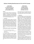
The GUI is shown in Fig. 1. In the lower part of the window, a user can
specify or upload user-defined scene and model files [11]. In the upper part of
the window, the newly created 3-D dynamic model is displayed with a VRML
browser [11]. It is important for readers to note that rube does not implement a
3-D “programming” GUI that, for instance, allows a user to construct a network
of 3-D objects that would be parsed by the GUI to automatically generate an
executable program, such as Najork’s CUBE [12]. In addition, unlike CUBE,
rube does not possess a formal “3-D syntax,” nor is it a set of 3-D representations of primitive data types and atomic operations.
Figure 1. rube’s GUI.
7
J. F. Hopkins and P. A. Fishwick
One major distinguishing feature of rube’s modeling architecture is that it
separates geometry from inter-object semantic relations [11]. Any scene file,
which represents geometry and appearance, can be used along with any model
file, which contains information about relations and behaviors of the model [11].
The rube development environment allows users to either create or reuse existing 3-D objects for the scene file, and allows users to create or reuse dynamic
models for the model file [11]. The freedom of defining and creating 3-D objects
has been given completely to the model author [11]. Objects can be personalized
and made culturally or aesthetically meaningful [4, 11, 13].
Placing rube in a Frame of Reference with Respect to Software
Visualization
To give readers a better idea of the characteristics of the rube framework, we
classify it according to the program visualization system taxonomy given by
Roman and Cox [14]. Within this taxonomy, there are three possible roles to be
played: programmer, animator, and viewer [14]. A rube developer is both the
programmer and animator, and anyone may be a viewer. At this time, we consider the primary viewing audience to be either the model author or someone
who is familiar with modeling in the context of rube. This slant may change in
the future, and we have been investigating both novice modelers and artistic
communities as possible users/audiences for the rube framework and its models.
Continuing with the axes of the taxonomy [14]:
•
•
•
•
Scope: rube does not automatically transform model code into page
layouts, such as flowcharts or statement-level diagrams. It is capable of
showing model data and control states, but the implementation of these
capabilities is up to the programmer/animator. Since rube is primarily
an event-based system, it is best adapted by programmers/animators for
relating model behavior.
Abstraction: rube is capable of direct, structural, and synthesized
model representation. However, rube primarily encourages structural
representation. Again, the implementation of these capabilities is up to
the programmer/animator. It is possible to implement “zooming” capabilities to provide low and high levels of abstraction to a user that is
navigating throughout a world.
Animation Specification Method: rube relies heavily on annotation by
the programmer/animator. Predefinition, declaration, and manipulation
do no play a role in rube.
Interface: rube inherits its graphical capabilities from VRML and its
successor, X3D. Thus, it can specify simple objects, compound objects,
visual events, and worlds. Within worlds, both absolute and constraintbased positioning are permitted. Multiple worlds (i.e., separate windows with separate objects that all represent alternate views of the
8
The rube Framework for Personalized 3-D Software Visualization
•
same model) are possible, but are not a not a focus of rube. Interaction
with the world by the viewer is managed through the VRML browser
and is programmer/animator defined. Interactive capabilities are often
implemented in the form of predefined controls. These controls can be
embedded in the image.
Presentation: rube is extremely flexible concerning interpretation of
graphics. Any accompanying text-based explanations must take into
account the intended audience. Since the audiences for rube models are
not yet well defined, we leave this issue to programmers/animators.
Programmers/animators need to be aware that others may not easily
grasp their display customizations, perhaps performed without regard
to related conventional or “obvious” styles of presentation. Accompanying detailed text-based explanations may be necessary. A rube visualization is capable of showing explanatory events and orchestrations.
The incorporation of aesthetic visual and audible elements in models
are encouraged by rube.
Najork and Brown’s Obliq-3D is a high-level, fast-turnaround system for
building 3-D animations that consists of an interpreted language that is embedded into a 3-D animation library [15]. There are some similarities between rube
and Obliq-3D. The languages used in both systems for specifying graphics objects have similar structure, expressive power, animation, and interactive capabilities. Both systems use interpreted languages (for rube: XML, VRML, X3D
and etc.), so both are “fast turnaround.” There are also some significant differences between rube and Obliq-3D. The rube development system is web-based
and portable (e.g., HTML, XML, VRML, X3D), while Obliq-3D is not (e.g., XWindows, Microsoft Windows, Modula-3, Obliq). VRML, X3D, and XML are
not strictly OO languages, while Obliq is. It should be easier to create graphical
structures, especially compound structures, in a free-form environment in rube
using third party tools that export VRML. In addition, geometric structures can
be easily reused for any purpose in rube. Sound can be incorporated as part of
rube models, while Obliq-3D does not mention this capability. Finally, rube and
Obliq-3D were designed around somewhat divergent goals: rube is more focused on aesthetics and modeling in a formal sense.
The Steps of the rube Modeling Methodology
The rube modeling and visualization methodology proposed by Fishwick [4]
consists of the following five steps:
1.
Choose system to be modeled: This could be anything from a system in
the real world (e.g., the Everglades ecosystem), to a typical software
system (e.g., database).
9
J. F. Hopkins and P. A. Fishwick
2.
3.
4.
5.
Select structural and dynamic behavioral model types: Here, modelers
specify the dynamic behavioral model types to be used in designing the
multimodel. These include CM, FSM, FBM, SDM, and others as previously listed. Next, modelers specify the dynamics and interactions
between the different models.
Choose a metaphor and/or an aesthetic style: Here, modelers develop
their own custom metaphors for the phenomena that they are modeling.
It is preferable that these metaphors have some readily apparent relationship to the phenomena being modeled, but the presence of such a
relationship is not required by rube. For example, modelers may
choose an architectural metaphor. Within architecture are many different aesthetic styles to choose from like Romanesque, Baroque, and Art
Deco.
Define mappings/Develop analogies: In this step, the modeler develops
a careful and complete mapping between the structural and dynamic
behavioral model type components and the metaphorical and stylistic
components. Although the rube development environment itself does
not specifically support the “automatic” or “assisted” mapping of a
software system to a visualization, it does offer guidelines for some
common modeling and programming constructs [4].
Create model: Here, the modeler combines the models and mappings
generated in the previous to synthesize the multimodel.
These original steps were derived before the current work in XML. Our current work assists the users in these steps as follows. For step 2, there are a set
number of dynamic mode types planned for rube and the formal XML schema
specification for two of them (FSM and FBM) are underway. Step 3 currently
remains manual. For step 4, there are guidelines but no programmatic assistance.
Step 5 includes significant assistance in the form of the Model Fusion Engine.
rube Example World
The following world briefly addresses the high-level development of a simple
model and its visualization in rube.
Steps 1: Choose System to be Modeled
We will specify a simple light bulb system that can be in three different states.
First, we must connect the bulb, by way of a ceramic base, to the wall socket.
This state is represented by an initial state of “disconnected.” Once the light is
connected, it moves to a second state of “off.” From there, it moves to “on” if a
chain is pulled. If the chain is pulled again, the light goes “off,” and so on.
10
The rube Framework for Personalized 3-D Software Visualization
Step 2: Select Structural and Dynamic Behavioral Model Types
The system that we chose in the previous step can be modeled well with an
FSM. Before we begin the development of our FSM, let us first give a basic
formal definition. A FSM is described by the set 〈T, U, Y, Q, Ω, δ, λ〉, where
•
•
•
•
•
•
•
T is the time base. T = ℜ (real numbers) for continuous time systems
and T = Z (integers) for discrete time systems.
U is the input set that contains all possible values that can be used as
input to the system.
Y is the output set that contains all possible values that can be output by
the system.
Q is the countable state set.
Ω is the set of acceptable input functions.
δ is the transition function, δ: Q x Ω → Q.
λ is the output function, λ: Q → Y.
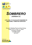
A simple FSM that describes our light bulb system is shown in Fig. 2. S1 represents “disconnected,” S2 represents “off,” and S3 represents “on.” Connecting
the bulb to the ceramic base activates the S1 → S2 transition (labeled with a
“1”). Pulling the chain to turn the light “on” and “off” alternately activates the
S2 → S3 and S3 → S2 transitions (both labeled with a “2”).
f
S1
1
U
Y
2
S3
S2
2
Figure 2. Example FSM
Our FSM is defined as follows:
•
•
•
•
•
FSM = 〈T, U, Y, Q, Ω, δ, λ〉
T = Z0+
U = { 1, 2 }
Y=Q
Q = { S1 (start state), S2, S3 }
11
J. F. Hopkins and P. A. Fishwick
•
•
•
Ω = 1 for t0, and 2 for all other T
δ: Q x Ω → Q
λ: Q → Y
In the first time step, the FSM will change state from S1 to S2. Thereafter,
on each time step, the FSM’s state will alternate between S2 and S3.
Step 3: Choose a Metaphor and/or an Aesthetic Style
Here, it is likely that a user would choose a single metaphor to represent the
system, or perhaps a group of metaphors and sub-metaphors to represent a complex system with many components. In this process, there would be no more
than one metaphor to map to each major model component in the following step
(i.e., step 4). However, for the sake of discussion, we choose two metaphors that
will map to our single FSM and we will show the application of these two metaphors to our example FSM in parallel during the remainder of the modeling
steps. This approach will show the flexibility of rube. One metaphor will involve water tanks, pipes, and water, and the other will involve gazebos, walkways, and a person. Both metaphors are conceptualized in 3-D.
Step 4: Define Mappings/Develop Analogies
The mappings between the water tank/pipe metaphor and the FSM are simple:
•
•
•
Water tanks represent states in our FSM. When a water tank is full, the
FSM is in the state represented by that water tank. Only one tank may
be full at a time. Since our FSM has three states, we will need three
water tanks. Each water tank will correspond to a specific state in our
FSM.
Transitions in our FSM are represented by water pipes. Water flows
from one tank to another over a pipe that connects the two tanks to represent the activity a transition. Since our FSM has three transitions, we
will need three water pipes. Each water pipe will correspond to a specific transition in our FSM.
The “data transfer token” implicit in our FSM is represented by water.
There is only one token, so there is a constant volume of water to correspond to the token. This volume is just enough to fill one tank of water, and all tanks should have the same volume.
12
The rube Framework for Personalized 3-D Software Visualization
Similarly, the mappings between the gazebo/walkway metaphor and the
FSM are simple:
•
•
•
Gazebos represent states in our FSM. When the person is in a gazebo,
our FSM is in the state represented by that gazebo. Since there is only
one person, only one state is active at a time. In addition, since our
FSM has three states, we will need three gazebos. Each gazebo will
correspond to a specific state in our FSM.
Transitions in our FSM are represented by walkways. The person
moves from one gazebo to another over walkways that connect the two
gazebos to represent the activity of a transition. Since our FSM has
three transitions, we will need three walkways. Each walkway will correspond to specific transition in our FSM.
The “data transfer token” implicit in our FSM is represented by the person.
Step 5: Create Model
Here is a basic outline of the steps involved in creating the models:
1.
2.
3.
4.
5.
Specify the basic FSM components, such as state and transition. Alternatively, take these components from a library. Place these in the
model file. Note: these components should be generic and be as nonspecific as possible to the model currently under construction.
Specify the FSM topology. That is, specify the number of states in the
FSM, and the arrangement of transitions that exist between the states.
Alternatively, take this topology from a library. Place this topology in
the model file.
Either by hand or with a third-party geometry-modeling tool, create
geometric 3-D analogs for each component of the FSM that will be
visualized. Alternatively, take these objects from a library. In the case
of our FSM, we could create cylindrical water tanks or gazebos to represent states, pipes or walkways to represent transitions, and water or a
person to represent the data transfer token. Place these objects in the
scene file.
Specify the animation behavior of the graphical components created in
the previous step. Alternatively, take these behaviors from a library. An
example behavior for water tanks is the “filling” or “emptying” of the
tanks with water. An example behavior for the walkways is the movement of the person over the walkways. Place these behaviors in the
model file.
Merge the scene and model files with the Model Fusion Engine’s GUI
interface.
13
J. F. Hopkins and P. A. Fishwick
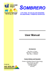
The implemented water tank world, authored by Donahue [16] is shown in
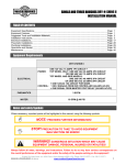
Fig. 3. The implemented gazebo world, authored by Kohareswaran [17] is
shown in Fig. 4.
Figure 3. Example FSM with water tank metaphor applied. Author: R. M. Donahue.
Figure 4. Example FSM with gazebo metaphor applied. Author: N. Kohareswaran.
14
The rube Framework for Personalized 3-D Software Visualization
Summary
Benefits of the rube Framework
The rube framework has the potential to make building 3-D visualizations easier
than is possible with other software visualization systems in direct proportion to:
1) the use of libraries of prefabricated geometric models, 2) the expressive
power of VRML, X3D, and XML and 3) the ease of use of third-party geometry
modeling tools. The issue of whether or not rube enables the creation of more
“effective” visualizations depends heavily on the programmer/animator and the
viewer. If the programmer/animator is the viewer, then benefits may be derived
from self-construction. If the viewer is not the author, then benefits may only
exist when the author has used “obvious” and/or traditional representation methods, provided extensive text-based explanations, or provided interactive controls
for the viewer. These speculations are based on research mentioned in the introduction to this paper [1, 2].
The rube framework’s contributions to the field of software visualization are
directly related to its progress toward the first two of its previously stated goals
Specifically:
1.
2.
To create a model design methodology and a software system that supports a separation of dynamic model specification from presentation
and visualization.
To work with the Fine Arts community in creating more personalized
and aesthetic presentations. The rube framework supports this effort by
promoting the integration of modeling with developer-defined visual
and audible elements.
The use of 3-D, metaphor-based visualization lends rube models aesthetic
and artistic aspects that are relatively novel in the realm of SV, and it would be a
notable achievement to blend SV with the creation of a work of art through the
vehicle of 3-D metaphor. An alternative course is to limit model visualization to
the creation of diagrams composed of abstract geometric shapes and symbolic
text. In essence, these shapes and text are wholly arbitrary forms of representation. As such, they generally lack intrinsic semantic content. Additionally, the
generic nature of these shapes and text lessens their potential aesthetic impact.
These shortcomings may be ameliorated if a developer is allowed and encouraged, by a framework like rube, to embellish these generic entities with customized, 3-D, metaphor-based visualizations.
We currently monitor related human-focused empirical research, and it is
our ultimate aim to generate empirical research centered on the use of the rube
development environment and modeling methodology. Before this sort of un-
15
J. F. Hopkins and P. A. Fishwick
dertaking, it is necessary to have an approximation of both the environment and
the methodology. Specifically, we wish to avoid a “catch 22” situation where
experiments cannot be executed without entanglement of experimental results
with issues related to tool quality, and quality tools cannot be constructed without solid empirical results as a design guide. We are still in the “exploring” and
“engineering” phases of our research. Although this chapter presents some preliminary results of our effort in rube’s development environment and modeling
methodology, more work is needed before we can reasonably proceed with human-based empirical research. We have very recently conducted a survey, with
general discussion, of aesthetic methods within a class on Modeling and Computer Simulation. The results from this survey are not yet available at the time of
this writing, but will be made available in the near future
In this chapter, we have provided an overview of the rube framework as well
as provided example worlds. The emphasis for rube is to permit modelers
greater freedom in building their own personalized software visualizations. We
briefly described a web-based graphical GUI that allows to users to merge 3-D
geometry, an XML model file, and pre-existing behaviors for animating and
simulating dynamic software models. Possible benefits of the rube framework
and future directions were discussed. As software engineering further leverages
modeling, our research may help in the mainstream future definition of 3-D
software visualization.
References
1.
2.
3.
4.
5.
6.
7.
8.
A. F. Blackwell, Metaphor in Diagrams (Ph.D. dissertation, Darwin College, Univ.
of Cambridge, Cambridge, UK, 1998).
C. D. Hundhausen, S. A. Douglas, and J. T. Stasko, A Meta-Study of Algorithm
Visualization Effectiveness (Journal of Vis. Lang. and Comp., in press).
P. A. Fishwick, rube (http://www.cise.ufl.edu/~fishwick/rube/intro/index.html,
2001).
P. A. Fishwick, Aesthetic Programming (Leonardo magazine, MIT Press, Cambridge, MA, to be published 2002).
R. M. Cubert, T. Goktekin and P. A. Fishwick, MOOSE: Architecture of an Object
Oriented Multimodeling Simulation System (Proc. Enabling Technology for Sim.
Sci., SPIE AeroSense 1997 Conf., Orlando, FL, USA, April 22-24, 1997) pp. 78-88.
P. A. Fishwick, SIMPACK: Getting Started with Simulation Programming in C and
C++ (1992 Winter Sim. Conf. Proc., Arlington, VA, USA, December, 1992), pp.
154-162.
K. Lee and P. A. Fishwick, OOPM/RT: A Multimodeling Methodology for RealTime Simulation (ACM Trans. on Modeling and Comp. Sim., 9(2), 1999), pp. 141170.
P. A. Fishwick, Simulation Model Design and Execution (Prentice-Hall, Englewood
Cliffs, NJ, 1995), 448 pp.
16
9.
10.
11.
12.
13.
14.
15.
16.
17.
The rube Framework for Personalized 3-D Software Visualization
P. A. Fishwick, N. H. Narayanan, J. Sticklen and A. Bonarini, A Multi-Model Approach to Reasoning and Simulation (IEEE Trans. on Syst., Man and Cybern.,
24(10), 1992), pp. 1433-1449.
P. A. Fishwick and B. P. Zeigler, A Multimodel Methodology for Qualitative Model
Engineering (ACM Trans. on Modeling and Comp. Sim., 2(1), 1992), pp. 52-81.
T. Kim and P. A. Fishwick, A 3D XML-Based Visualization Framework for Dynamic Models (2002 Web3D Conference in Monterey, CA, submitted 2001).
M. Najork, Programming in Three Dimensions (Ph.D. dissertation, Univ. of Illinois
at Urbana-Champaign, 1994).
T. Kim and P. A. Fishwick, Virtual Reality Modeling Language Templates for Dynamic Model Construction (Enabling Technology for Sim. Sci., SPIE ‘01 AeroSense Conference, Orlando, FL April 2001).
G. C. Roman and K. C. Cox, A Taxonomy of Program Visualization Systems (IEEE
Computer, 26(12), 1993), pp. 11-24.
M. A. Najork and M. H. Brown, Obliq-3D: A High-Level, Fast-Turnaround 3D
Animation System (IEEE Trans. on Vis. and Comp. Graphics, 1(2), 1995), pp. 175193.
R. M. Donahue, Industrial Plant Metaphor with a Change in Geometry
(http://www.cise.ufl.edu/~fishwick/rube/tutorial/Fsm4/world4.wrl, 2001).
N.
Kohareswaran,
World
with
a
Human
Agent
Metaphor
(http://www.cise.ufl.edu/~fishwick/rube/tutorial/Fsm5/world5.wrl, 2001).