1
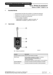
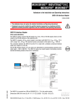
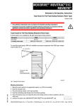
MOVITRAC® 07 Frequency Inverter
Addendum to Operating Instructions
1
Option "Parameter Module"
Edition: 07/2001 / 10522719 / en
Features
•
Saving of data from the inverter in the parameter module
•
Playback of data from the parameter module into the inverter
•
Display of operating state
•
Supported unit types:
– MOVITRAC® 07 LOGODrive as of firmware .10
– MOVITRAC® 07 standard version as of firmware .13
1.1
Frontal view
04944AXX
Fig. 1: Parameter module
Element
Description
[1] Connection cable with plug
Western plug for connection to inverter
[2] Three-color LED
green: data present in parameter module
green flashing: transmission in progress
yellow: no data in parameter module
red: transmission error
red flashing: transmission impossible (parameter lock / enable)
[3] DOWNLOAD key
Data are transmitted from the parameter module to the inverter
[4] UPLOAD key
Data are transmitted from the inverter to the parameter module
SEW-EURODRIVE GmbH & Co ♦ P.O. Box 3023 ♦ D-76642 Bruchsal
Tel. (+49) 7251 75-0 ♦ Fax (+ 49) 7251 75-1970 ♦ Telex 7 822 391
1
MOVITRAC® 07 Frequency Inverter
Addendum to Operating Instructions
2
Operation
2.1
Connection
Option "Parameter Module"
Edition: 07/2001 / 10522719 / en
The parameter module is equipped with a short piece of cable and a Western plug. This
plug is connected to X11 (RS-485) for MOVITRAC® 07.
Fig. 2: Connection to MOVITRAC® 07
2.2
04965AXX
Data from parameter module to the inverter
Use the DOWNLOAD key to copy all unit data from the parameter module to the
inverter. All data have to be present in the parameter module for this step (LED green).
The inverter must be inhibited to transmit the data, e.g. by pressing the Stop key. Use
the Download key for the next step.
The green light will be flashing in the LED during the copying process and become
steady once the copying process has been finished (data present). The error message
F-97 (copy error) will appear on the inverter display in case of a copy error. The error
can be reset by copying a complete data set from the parameter module into the inverter
or by performing a factory setting.
After the loading process, the inverter can be started by pressing the RUN key or turning
the power supply on/off.
The data will not be transmitted in case:
•
the inverter is enabled
•
the P803 parameter lock has been set to ON
SEW-EURODRIVE GmbH & Co ♦ P.O. Box 3023 ♦ D-76642 Bruchsal
Tel. (+49 7251) 75-0 ♦ Fax (+ 49 7251) 75-1970 ♦ Telex 7 822 391
2
MOVITRAC® 07 Frequency Inverter
Addendum to Operating Instructions
2.3
Option "Parameter Module"
Edition: 07/2001 / 10522719 / en
Data from the inverter to the parameter module
You can copy all unit data from the inverter to the parameter module with the UPLOAD
key.
The green light will be flashing in the LED during the copying process. There will be a
red light in the LED for two (2) seconds in case of an error in the copying process. There
will be a steady green light in the LED after a successful copying process (data present).
A steady yellow light in the LED indicates an error in the copying process (no data present).
2.4
Storing the device
For storage purposes, simply plug the cable into the appropriate receptacle on the back
of the parameter module.
04967AXX
Fig. 3: Rear side of unit with stored cable
You can then slide the parameter module from the top onto the cover of the
MOVITRAC® 07 unit. Simply reverse the process to remove the parameter module.
Fig. 4: Mounted parameter module
SEW-EURODRIVE GmbH & Co ♦ P.O. Box 3023 ♦ D-76642 Bruchsal
Tel. (+49) 7251 75-0 ♦ Fax (+ 49) 7251 75-1970 ♦ Telex 7 822 391
3