Download Installation Manual Peristaltic Dispenser PD12 OEM


Transcript
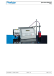
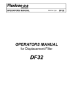
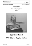
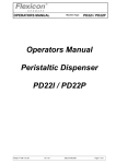
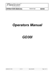
PD12 OEM
Installation Manual
Re.: Installation
Rev.: 1.03
Date: 2008-05-30
Page 1 of 14
Installation Manual
Peristaltic Dispenser
PD12 OEM
File:
PD12 OEM IM 1.03 EN
PD12 OEM
Installation Manual
Re.: Installation
Rev.: 1.03
Date: 2008-05-30
Page 2 of 14
1 Table of Contents
1
2
3
3.1
3.2
4
5
5.1
5.2
5.3
5.4
5.5
5.6
6
7
7.1
8
Table of Contents......................................................................................................................... 2
Installation - General.................................................................................................................... 3
Installation of PD12 OEM dispenser head and control unit ..................................................... 4
Installation of PD12 OEM dispenser head ................................................................................. 4
Installation of PD12 OEM control unit ........................................................................................ 6
Electrical connection of PD12 OEM ........................................................................................... 7
Integration of the PD12 OEM into the filling machine control system .................................... 8
Stepper Motor Connector – X1 .................................................................................................. 9
Inputs Connector – X2 ............................................................................................................. 10
Outputs Connector – X3........................................................................................................... 11
X4 Mains supply connector ...................................................................................................... 11
Addressing of filling station ...................................................................................................... 12
Connection to NET connector on Master Controller MC12 ...................................................... 12
Selection of internal or external supply for Controller PCB .................................................. 13
Change of voltage ...................................................................................................................... 14
Change of voltage .................................................................................................................... 14
Copyright .................................................................................................................................... 14
File:
PD12 OEM IM 1.03 EN
PD12 OEM
Installation Manual
Re.: Installation
Rev.: 1.03
Date: 2008-05-30
Page 3 of 14
2 Installation - General
This manual only relates to incorporation of the PD12 OEM into a filling machine.
Please refer to PD12 OEM operator’s manual and MC12 operator’s and reference manuals for daily
use of the PD12 OEM.
The installation of the PD12 OEM consists of
• Installation of dispenser head and control unit
• Electrical connection of the various parts of the filling system
• Integration of the PD12 OEM into the filling machine control system
File:
PD12 OEM IM 1.03 EN
PD12 OEM
Installation Manual
Re.: Installation
Rev.: 1.03
Date: 2008-05-30
Page 4 of 14
3 Installation of PD12 OEM dispenser head and control unit
3.1 Installation of PD12 OEM dispenser head
The dispenser head must be mounted through a solid wall. The wall must have a thickness of 17 to
19 mm.
Fig. 3-1
The dispenser head can be mounted in either vertical or horizontal position. The only orientation that
cannot be used is horizontal with the tube bridge facing downwards. All other orientations will not
affect the performance of the dispenser.
It must be observed that sufficient space around the dispenser head is available to allow change and
positioning of tubes. These minimum distances must also be observed, when installing more than one
dispenser in the same wall.
File:
PD12 OEM IM 1.03 EN
PD12 OEM
Installation Manual
Re.: Installation
Rev.: 1.03
Date: 2008-05-30
Page 5 of 14
Fig. 3-2
Also the length of the dispenser head in front of the wall and the depth of the drive system behind the
wall must be observed to allow mounting and service of the dispenser.
Use dimensions below for mounting holes.
Fig. 3-3
File:
PD12 OEM IM 1.03 EN
PD12 OEM
Installation Manual
Re.: Installation
Rev.: 1.03
Date: 2008-05-30
Page 6 of 14
3.2 Installation of PD12 OEM control unit
The PD12 OEM control unit is intended for mounting on a flat vertical surface inside the filling
machine control cabinet. The control unit is intended for mounting on 3 pcs M6 Allen screws with
cylindrical head.
Fig. 3-4
It must be observed that sufficient space around the control unit is available to allow mounting of the
unit and ventilation. The rear side of the control unit, that contains all electrical connections, must be
accessible.
Fig. 3-5
File:
PD12 OEM IM 1.03 EN
PD12 OEM
Installation Manual
Re.: Installation
Rev.: 1.03
Date: 2008-05-30
Page 7 of 14
4 Electrical connection of PD12 OEM
The various parts of the filling system must be connected as shown in the connection block diagram
below.
All necessary connectors are supplied with the machine, but cables are not included.
Use 8 x 0,5 mm2 wire for cable between stepper motor and controller.
Tube Bridge Sensor
Pump Head
Stepper Motor
PD12 OEM Controller
X1
X2
X3
X2
X2
Status
MC12 Master Controller
FlexNet
Net
24V supply
Control
X3
External Controller (PLC)
Optional Data Exchange
Fig. 4-1
Each connector and corresponding electrical and functional specification is described in the following
section.
File:
PD12 OEM IM 1.03 EN
PD12 OEM
Installation Manual
Re.: Installation
Rev.: 1.03
Date: 2008-05-30
Page 8 of 14
5 Integration of the PD12 OEM into the filling machine control system
Integration of the PD12 OEM into the filling machine control system must be carried out according to
the technical description of the electrical interface below.
The PD12 OEM has the electrical interface on the rear side of the cabinet. It consist of 4 PHOENIX
connectors, connecting to Stepper Motor, Inputs, Outputs and Mains power.
Rear view
X1
X1
1
8
H1
Pin No.
1-2
Stepper Motor A+
3-4
Stepper Motor A-
5-6
Stepper Motor B+
7- 8
Stepper Motor B-
H2
H3
X2
X2
1
Pin No.
1
External Supply
0V
2
External Supply
+24V
3
DISABLE Input
(EXT 2)
4
START Input
(EXT 1)
5
PRIME Input
6
FlexNet
DATA
7
FlexNet
GND
8
FlexNet
/DATA
1
Mains Supply
OK
2
BUSY 3
PNP Output
+24V / max. 300 mA
3
BUSY 2
PNP Output
+24V / max. 300 mA
4
BUSY 1
NPN Output
0V / max. 300 mA
5
SAFETY Sensor
Output
+24V / max. 200 mA
6
SAFETY Sensor
Input
+24V
8
X3
1
6
X3
X4
1
3
LED Indicators
X4
Pin No.
Pin No.
H1
+24V Power to Pump Controller
1
Mains Supply
FASE
H2
Communication to Master Controller
2
Mains Supply
EARTH
H3
BUSY 3 Indicator
3
Mains Supply
ZERO
Fig. 5-1
File:
PD12 OEM IM 1.03 EN
+24V Out
PD12 OEM
Installation Manual
Re.: Installation
Rev.: 1.03
Date: 2008-05-30
Page 9 of 14
5.1 Stepper Motor Connector – X1
The stepper motor is connected to X1 by an 4 or 8 wire straight cable.
If the cable mounted on stepper motor is too short, an extra cable according to drawings below must
be used.
Note that cable with screen must be used.
Mounting of 4 wire straight cable.
PD12 OEM
Connector X1
Stepper Motor
8
4
4
3
3
2
2
1
1
1
1
8
8 pole PHOENIX
male Connector
8 pole PHOENIX
female Connector
Screened cable
4 wires min 0.75 mm2
for 20 m cable
Fig. 5-2
Mounting of 8 wire straight cable.
8
8
8
7
7
6
6
5
5
4
4
3
3
2
2
1
1
1
8 pole PHOENIX
male Connector
8
Screened cable
8 wires min 0.50 mm2
for 20 m cable
Fig. 5-3
File:
PD12 OEM IM 1.03 EN
1
8 pole PHOENIX
female Connector
PD12 OEM
Installation Manual
Re.: Installation
Rev.: 1.03
Date: 2008-05-30
Page 10 of 14
5.2 Inputs Connector – X2
Pin 1
Pin 2
External Supply 0V
External Supply +24V
The external DC supply for Controller PCB 20-214-005 is normally supplied by the controlling
equipment, for example the main power supply from the machine, the PD12 OEM is mounted in.
This supply makes it possible to turn OFF the Mains Supply connected to X4, when for example an
emergency stop requires to power to be removed from the stepper motor and still have the Master
Controller (MC12) communicating with pump controller, so avoiding a restart of the filling system.
Pin 3
DISABLE input
This Input can be used for disabling the pump from reacting
on a START signal on Pin 4 or used for special functions
+24V / max. 5 mA load.
Pin 4
START input
This Input is used for START signal to the pump to make a
dispense.
+24V / max. 5 mA load.
Pin 5
PRIME input
This Input is used for PRIMING (Purging), the pump will run
with approx. 125 rpm when applying +24V on this pin, stops
when the +24V is removed
+24V / max. 10 mA load.
Pin 6
FlexNet
RS485 Connection
DATA
Pin 7
FlexNet
RS485 Connection
GND
Pin 8
FlexNet
RS485 Connection
Inverted DATA
The FlexNet is used for serial communication between the PD12 OEM and
the Master Controller (MC12). The cable can be twisted pair or screened
with a max. Length of 300 feet (100 m).
All Inputs can be wired in parallel, so a double terminal connector is used for X3 to ease these
connections.
File:
PD12 OEM IM 1.03 EN
PD12 OEM
Installation Manual
Re.: Installation
Rev.: 1.03
Date: 2008-05-30
Page 11 of 14
5.3 Outputs Connector – X3
Pin 1
Mains supply Indicator output
+24V max. 300 mA load.
This output is used to monitor the mains internal fuse and mains supply for the pump
controller.
Pin 2–4
Status Outputs
These outputs are all active, when the pump is priming, dispensing or pumping.
Pin 2
BUSY 3
PNP Output +24V max. 300 mA load.
This output is active when the Controller PCB is active and the Stepper Motor Controller
is sending step-pulses to X1. (This output is checking the Fuse on 20-312-002).
This output does NOT include the functionality from Timer 18 and Timer 19 (see MC12
Manual).
Pin 3
BUSY 2
PNP Output +24V max. 300 mA load.
This output is active when the Controller PCB is active and includes the functionality
from Timer 18 and Timer 19 (see MC12 Manual)
Pin 4
BUSY 1
NPN Output
OC to 0V max. 100 mA load.
This output is active when the Controller PCB is active and includes the functionality
from Timer 18 and Timer 19 (see MC12 Manual)
Pin 5
Tube-bridge sensor output
+24V max. 200 mA load.
Pin 6
Tube-bridge sensor input
+24V max. 5 mA load.
The tube-bridge sensor input is normally used to inhibit the pump from starting priming,
dispensing or pumping, when the tube-bridge is not mounted.
If the +24V is remove during either priming, dispensing or pumping, the pump will stop
immediately.
The MC12 has information of the status of the tube-bridge sensor input.
5.4 X4
Mains supply connector
Pin 1
Mains supply FASE
Pin 2
Mains supply EARTH
Pin 3
Mains supply ZERO
File:
PD12 OEM IM 1.03 EN
PD12 OEM
Installation Manual
Re.: Installation
Rev.: 1.03
Date: 2008-05-30
Page 12 of 14
5.5 Addressing of filling station
Address
SW1
SW2
SW3
SW4
1
1
1
1
1
2
0
1
1
1
3
1
0
1
1
4
0
0
1
1
5
1
1
0
1
6
0
1
0
1
7
1
0
0
1
8
9
0
1
0
1
0
1
1
0
Fig. 5-4
10
0
1
1
0
11
0
0
1
0
12
1
1
0
0
13
0
1
0
0
14
1
0
0
0
15
1
0
0
0
16
0
0
0
0
Address "1" is the factory setting of PD12.
If the PD12 is one of several filling stations in a system, none of the stations may have the same
address and it must therefore be changed.
Change of address is performed via a dip-switch placed at the bottom of the PD12. This change may
only be carried out when the machine is turned off at the main isolator.
Addresses between 1 and 16 may be chosen, and Fig. 5-4 shows the various combinations.
5.6 Connection to NET connector on Master Controller MC12
The PD12 OEM control unit must be connected to NET connector on Master Controller MC12 by use
of a 4-pin DIN connector (supplied with MC12).
The NET connector on MC12 has following pin configuration.
2
1
GND
3
DATA
4
/DATA
Fig. 5-5
Pin 1
Pin 2
Pin 3
Pin 4
/DATA
GNC
Not used
DATA
File:
PD12 OEM IM 1.03 EN
Connect to X2.8
Connect to X2.7
NA
Connect to X2.6
PD12 OEM
Installation Manual
Re.: Installation
Rev.: 1.03
Date: 2008-05-30
Page 13 of 14
6 Selection of internal or external supply for Controller PCB
During manufacture of the PD12 OEM, external 24 VDC supply for Controller PCB is chosen, but
internal 24 VDC supply of Controller PCB can be chosen.
Note that if internal supply is chosen, restart of MC12 will be necessary in the event of missing or
disabled power supply of PD12 OEM.
Fig. 6-2
Fig. 6-1
On the distribution PCB the Jumper JP1 (located between CON5 and CON9) is used to select the
24VDC supply for the Controller PCB 20-214-005.
Position
1-2
2-3
Description
Internal 24VDC supply
External 24VDC supply on X2
File:
PD12 OEM IM 1.03 EN
(default)
PD12 OEM
Installation Manual
Re.: Installation
Rev.: 1.03
Date: 2008-05-30
Page 14 of 14
7 Change of voltage
7.1 Change of voltage
Fig. 7.1
The PD12 can be converted to accept another supply voltage.
The conversion can be made inside the machine by moving the cables of the transformer clamps.
8 Copyright
Copyright (c) 2008 Watson-Marlow Flexicon. All rights to this manual belong to Watson-Marlow
Flexicon. Neither the complete manual nor parts of it may be translated, copied, printed or published
in any form or by any means without permission in writing from Watson-Marlow Flexicon.
Watson-Marlow Flexicon is convinced that the information of this manual is correct, but WatsonMarlow Flexicon cannot be held responsible for it.
Watson-Marlow Flexicon reserves the right to update and amend this manual without previous notice.
Watson-Marlow Flexicon is under no obligation to update manuals already published.
File:
PD12 OEM IM 1.03 EN