Download USER GUIDE July 2000 - ICS Electronics Ltd
Transcript
1$95
86(5*8,'(
-XO\ 1$95 8VHU *XLGH
VESSEL IDENTIFICATION INFORMATION
Name
Call Sign
MMSI
NAV5 S/N
ICS Electronics Limited.
Unit V, Rudford Industrial Estate
Ford, Arundel, West Sussex
BN18 0BD
United Kingdom
Tel: +44 (0)1903 731101
Fax: +44 (0)1903 731105
E-Mail: sales@icselectronics.co.uk
Website: www.icselectronics.co.uk
The technical data, information and illustrations contained in this publication were to the best of our knowledge
correct at the time of going to print. We reserve the right to change specifications, equipment, installation and
maintenance instructions without notice as part of our policy of continuous product development and improvement.
No part of this publication may be reproduced, stored in a retrieval system or transmitted in any form, electronic or
otherwise without permission from ICS Electronics Ltd. No liability can be accepted for any inaccuracies or
omissions in the publication, although every care has been taken to make it as complete and accurate as possible.
Copyright 2000, ICS Electronics Limited. All rights reserved.
2
1$95 8VHU *XLGH
&217(176
INTRODUCTION
5
OPERATION
6
INITIAL OPERATION
6
Changing the Paper Roll
7
NAVTEX Message type selection
NAVTEX stations set up procedure
NAVTEX message category set up procedure
NAVTEX message categories types
9
9
10
11
SYSTEM ALARMS
12
DUAL CHANNEL OPERATION
13
INSTALLATION
14
MECHANICAL MOUNTING
14
ELECTRICAL CONNECTIONS
15
NAVTEX ANTENNA
17
NAV-PSX
22
SELF TEST
23
TROUBLE SHOOTING GUIDE
25
SPECIFICATION
27
NAVAREA WORLD MAP
28
NAVTEX Station Designations
28
3
1$95 8VHU *XLGH
This page is intentionally left blank
4
1$95 8VHU *XLGH
,1752'8&7,21
NAVTEX is a method of transmitting navigational warnings and weather
forecasts from designated coast radio stations. All English language
transmissions are made on 518 kHz and each station is allocated several
time ‘slots’ during the day, when it is permitted to transmit. These are
normally at four hourly intervals. The only exceptions to this are gale
warnings and search and rescue messages, which may be transmitted at
any time.
Reception of NAVTEX is normally limited to an area of 200 - 300 miles
radius around each transmitting station, although considerably greater
ranges can be possible at night.
Subject to IMO approval, additional local language transmissions may be
made on 490 kHz and tropical transmissions may be made on 4209.5 kHz.
This latter frequency has a much greater range and is less susceptible to
static noise than the other two frequencies.
The NAV5 has been designed to the latest European and International
specifications to provide up to date weather and navigation warning
information to commercial vessels. It meets IMO requirements under
GMDSS and is designed for simplicity of operation. It will provide reliable
printed information day after day within designated NAVTEX coverage
areas.
Installation is straightforward. Connect the NAV5 to a 12 or 24 volt DC
supply and connect the antenna. Switch it on, and it will start printing
NAVTEX messages without further manual intervention.
Left in this state, the NAV5 may overwhelm you with information. It can
therefore be set up to print only those stations and message categories you
want to receive and which are applicable to the area in which you are
sailing.
Normally, routine messages are repeated at four hourly intervals. Provided
that the NAV5 is left running ‘repeat message’ transmissions are not
printed again within three days (72hours).
Permanent installation of the NAV5 can be made with the bulkheadmounting bracket provided. Alternatively, the optional FMT-2 flush panel
mounting kit may be purchased.
•
A NAVTEX antenna should be mounted ‘elevated’ clear of metal
objects in a location where it cannot easily be damaged.
5
1$95 8VHU *XLGH
23(5$7,21
,1,7,$/ 23(5$7,21
Switch on the NAV5 by pressing the P power button
The LCD display back light will come on
The LCD data display will show:-
ICS
NAV-5
LOG
EMPTY
The NAV5 is now ready to receive NAVTEX messages.
The factory default setting is for all NAVTEX stations and message
categories to be printed.
To change the settings, refer to SET UP section.
Set-up controls
The main functions of the front panel controls are shown in the following
diagram:-
6
1$95 8VHU *XLGH
&KDQJLQJ WKH 3DSHU 5ROO
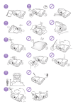
The NAV5 is supplied with one roll of paper fitted. When this paper roll is
completely used up, the NAV5 will sound an alarm and printing will stop.
Early warning that the paper is about to run out is given by red stripes on
the paper.
Should the paper run out in the middle of a message, information will not
be lost provided the NAV5 is not switched off.
• To remove the remaining paper, open the door by pushing it in to
release the door latch. The door will then open downwards.
• Remove the old paper roll and tear off the paper where it enters the
printer mechanism. Remove the plastic spindle. Press the F button to
feed any remaining paper through the print mechanism.
DO NOT PULL THE PAPER THROUGH THE PRINTER AS THIS MAY
DAMAGE THE PRINT HEAD.
• Place the new roll onto the spindle with the paper emerging from the top
of the roll towards you.
• Turn the paper upwards through 180 degrees and insert it into the slot
at the base of the printer mechanism, (which is above the paper roll), as
far as it will go.
It is important that the edge of the paper is straight and undamaged
and that the paper is dry.
7
1$95 8VHU *XLGH
• Push the F button to feed the paper until it clears the door exit.
• Push the S button, to print any stored messages.
Check that the paper roll is correctly aligned with the print mechanism.
CORRECT
INCORRECT
Paper roll type is ‘heat sensitive paper’ with heat sensitive side
outermost. Paper roll size is 80mm wide x 20m total length of paper.
Overall maximum diameter of roll not greater than 42mm, roll
mounting spindle internal diameter is 12mm.
New supplies of paper rolls can be ordered from ICS dealers or directly
from ICS. Quote order code: NAVTEX Rolls. This specifies a box of eight
rolls of paper.
8
1$95 8VHU *XLGH
1$97(; 0HVVDJH W\SH VHO
VHOH
HFWL
FWLR
RQ
At the beginning of each NAVTEX message there is a message header,
this identifies the source and nature of message using an identity code.
For example GA59 :-
Station
Message category
Serial No.
GA59
This identifies which station has transmitted the message and the nature of
the message.
It is possible to select the NAVTEX stations you wish to receive messages
from and to restrict certain message categories.
NAVTEX stations set up procedure
Enter the NAVTEX set up mode by pressing the
the transmitting station selection display.
f
button, this brings up
STN:
ABCDEFGHIJ
KLMNOPQRSTUVWXYZ
f
c
d
Press
followed by either the
or the
buttons, one push of
either button will select, a second push will deselect.
deselected stations are indicated by a ‘dash’ – .
Each NAVTEX transmitting station has its own identifying letter. A list of
these can be found in the NAVTEX Station Designations table section of
this manual.
9
1$95 8VHU *XLGH
If you do not know which stations cover your area, start by leaving them all
stations selected. You will soon find which stations are relevant to you.
NAVTEX message category set up procedure
• Once you have completed the NAVTEX station selection, press
change to the message category selection screen
e
to
M S G:
ABCDEFGHIJ
KLMNOPQRSTUVWXY
Message categories are identified by a single letter.
f
d
c
Press
followed by either the
or the
buttons, one push of
either button will select, a second push will deselect.
deselected stations are indicated by a dash – .
• Message categories, A,B,D and L cannot be deselected.
Press
e
to store the NAVTEX station and message category selections.
10
1$95 8VHU *XLGH
NAVTEX message categories types
A . . . . . . . . . . . . . . . . Navigation warnings
B . . . . . . . . . . . . . . . . Meteorological warnings
C . . . . . . . . . . . . . . . . Ice reports
D . . . . . . . . . . . . . . . . Search and rescue information
and pirate attack warnings
E . . . . . . . . . . . . . . . . Meteorological forecasts
F . . . . . . . . . . . . . . . . Pilot service messages
G . . . . . . . . . . . . . . . . DECCA information
H . . . . . . . . . . . . . . . . LORAN information
I . . . . . . . . . . . . . . . . OMEGA information
J . . . . . . . . . . . . . . . . SATNAV information
K . . . . . . . . . . . . . . . . Other electronic navaid information
L . . . . . . . . . . . . . . . . Navigational warnings additional to letter A
V . . . . . . . . . . . . . . . . Amplifying details to navigational warnings
initially broadcast under A
Z . . . . . . . . . . . . . . . . No messages on hand
Message categories A, B, D and L cannot be de-selected.
International regulations preclude these message categories from being
de-selected.
11
1$95 8VHU *XLGH
6<67(0 $/$506
The alarm signal within the NAV5 will sound under the following
circumstances:• INCORRECT KEY PRESSED
• PAPER OUT
• LOW BATTERY ( Power supply voltage is less than 9 volts)
• VITAL NAVTEX MESSAGE
Press the S key to stop the alarm.
Note:
Remove the cause of the alarm first.
12
1$95 8VHU *XLGH
'8$/ &+$11(/ 23(5$7,21
* Only applicable when the NAV5 second channel option is installed
Follow these instructions in conjunction with the normal set-up instructions,
in some places the following instructions take precedence.
c
d
The
and
keys on the keypad are used to switch the LCD display
between showing RX-A (the standard 518kHz receiver) and RX-B ( the
second receiver). The LAST MSG display shows the identity number of the
last message received on that receiver and the two-dot signal indicator will
flash if there is a signal being received from that receiver.
•
c
or
Pressing the
the other receiver.
d
will display the corresponding information for
f
When the
key is pressed, the set up mode for the selected receiver
will be started. This enables the stations and message types required for
that receiver to be set.
The two receivers are set up independently.
f
c
Press
followed by either the
or the buttons, one push of either
button will select, a second push will deselect or vice versa.
deselected stations / categories are indicated by a ‘dash’ – .
Press
e
to store the NAVTEX station and message category selections.
Note:
Although the
and
keys are used to select which receiver is shown
on the display, it is important to realise that both receivers are actively
receiving signals all the time.
c
d
If messages are being transmitted at the same time on both channels, both
messages will be received and printed.
Messages from RX-B are identified separately on the printout.
13
1$95 8VHU *XLGH
,167$//$7,21
NAV5 system overview
Voltage for the NAV-ACTIVE active
antenna is not supplied directly by the
NAV5, a separate antenna power
supply unit is provided
0(&+$1,&$/ 02817,1*
The standard bulkhead mounting bracket can be used to mount the NAV5
above or below a horizontal (or near horizontal) surface. If the NAV5 is to
be mounted through a flat panel, it is advised that you purchase the FMT-2
flush mounting kit option.
DO NOT MOUNT THE NAV5 IN A POSITION WHERE
SEA SPRAY CAN REACH IT, OR WHERE IT MAY BE
EXPOSED TO DIRECT SUNLIGHT.
14
1$95 8VHU *XLGH
(/(&75,&$/ &211(&7,216
A connection must be made to a 12 or 24 volts DC supply via a circuit
breaker capable of supplying at least 2 amps. Connection should be to the
ships ‘radio battery’ and be in accordance with GMDSS requirements.
•
Connections are made directly to the screw terminals on the NAV5
mating connector at the rear of the unit using the 1m length cable
provided.
•
Use cable ties to restrain the wiring from any vibration, which might
weaken it over a prolonged period. The connecting cables should be
restrained from movement by securing them to the rear of the NAV5
(bracket) or to adjacent metalwork.
Safety Warning
The ICS NAV5 has been designed and manufactured to be
completely safe when used in accordance with the instructions
given in this manual. To ensure that the complete installation is
safe, it is essential that a fuse or circuit breaker is installed in the
supply cable as described in the Installation Section of this manual.
The NAV5 is supplied with a DC power cable and in-line 2.5 amp
fuse. It is essential that this fuse is included in the installation and
that the Green wire connected to pin 2 (with antenna screen)
should be connected to a nearby (hull) grounding point.
15
1$95 8VHU *XLGH
INTERFACE CONNECTIONS
The NAV5 rear panel connections are as follows:PIN
FUNCTION
1.......................
2.......................
Antenna A
Antenna A screen &
Vessels grounding earth point
Antenna B
Antenna B screen
Not Used
Not Used
Power input negative
Power input positive
Auxiliary Alarm Contact
Auxiliary Alarm Contact
3.......................
4.......................
5.......................
6.......................
7.......................
8.......................
9.......................
10. . . . . . . . . . . . . . . . . . . . . .
NOTES:
Pin 1 is located closest to the right hand edge of the NAV5 case, looking
from the rear.
• When using a second antenna, link terminals 4 to 2 for grounding
purposes.
• The auxiliary alarm contact is capable of switching up to 24 volts DC at
up to one amp and is volt free.
• The power supply input is isolated from the case and antenna, it must
remain within the range 10-30 volts DC at all times.
To ensure the best possible protection of the NAV5 from static
electricity or nearby lighting strikes, the pre-fitted green grounding
wire (pin 2) must be connected to a nearby (hull) electrical grounding
point.
16
1$95 8VHU *XLGH
1$97(; $
$1
17(11$
Several different antenna types are recommended for the NAV5:• The NAV-ANT/a passive antenna with NAV-CLAMP/a mounting bracket
and NAV-CABLE 20m coaxial cable kit.
• ANT4/a passive antenna with 1” x14 t.p.i. mounting screw thread and
10m of pre-fitted coaxial cable
• NAV-ACTIVE broad band active antenna, with antenna power unit with
20m of coaxial cable. Recommended for dual channel use.
• BB-1 long wire or un-tuned whip antenna 50Ω coupling transformer with
15m of coaxial cable.
The NAV5 must be used with a low impedance 50Ω antenna.
A ‘miss matched’ or ‘high impedance’ whip or wire antenna should not be
used or the operational range of NAVTEX reception will be greatly reduced.
•
If a ‘Wire’ or ‘long whip’ antenna is used with the NAV5 it must be fitted
with a 50Ω matching transformer.
If the NAV5 has a ‘Dual Channel’ option fitted, refer to the Dual Channel
antenna installation instructions near the end of this section.
NAVTEX antenna must be mounted clear of obstructions well
away from other antennas by at lest 0.5 metres.
Ensure that they cannot be snagged by mooring warps or
running rigging or engulfed by green water.
They should always be mounted vertically.
17
1$95 8VHU *XLGH
INSTALLATION OF NAVTEX ANTENNA
NAVTEX antenna should be mounted vertically, in an elevated position.
Metal, rigging or other antenna must not be located in the 'NO GO cone'
surrounding the upper part.
18
1$95 8VHU *XLGH
Installation procedure, NAV-ANT/a, NAV-CABLE, NAV-CLAMP/a
Start the antenna cable installation from the NAV5 (lower) end first.
Where the cable passes through bulkheads or decks, waterproof deck
glands should be installed. Securely fasten the cable against vibration
using plastic cable tie wraps.
19
1$95 8VHU *XLGH
Antenna connection
Pass the cable though the 'black plastic boot', prepare the end of the cable
as shown in the diagram, folding the cable braid back and screwing the
PL259 connector firmly in place. To ensure a good connection it is
recommended that the centre pin is soldered.
Side pin (2)
Centre pin (1)
NAV-CABLE assembly detail
NAV5 connection
Connect the centre pin of the antenna cable to terminal 1 and the side pin
to terminal 2 of the NAV5 rear connector.
If required, the NAV-CABLE may be extended with 50ohm coaxial cable
and connectors. The maximum cable length should not exceed 100m.
Ensure that any cable joints are well secured and waterproofed using selfamalgamating (rubber) tape.
NAV-ACTIVE INSTALLATION
• Securely mount the NAV-ACTIVE antenna to a vertical surface or pole
using the bracket provided, route the connecting cable though to the
NAV5 using cable glands to pass though bulkheads as required.
Connect the NAV-ACTIVE antenna output coaxial cable centre core to
Terminal 1 of the NAV5 connector block and the screen to Terminal 2.
• Connect the ‘positive’ supply brown wire and the ‘negative’ supply Blue
wire from the AAX1 Antenna Power Supply Unit to the vessels 12 or
24Vdc power supply. Refer to the fitting instructions packed with the
antenna for further information.
Note:
The NAV5 does not directly provide power for an Active Antenna.
20
1$95 8VHU *XLGH
DUAL CHANNEL NAV5 NAVTEX ANTENNA
Two versions of second channel receiver are currently available for the
NAV5, 490kHz(National Language) or 4209.5 kHz (Tropical Area). If one of
these options is fitted, the NAV5 must be used with a wide band antenna
that covers both 518kHz and the second channels operating frequency.
•
Two separate antennas can be connected to the NAV5.
DUAL ANTENNA INSTALLATION
If the NAV5 has been supplied with an ICS NAV-ANT/a 518kHz Passive
NAVTEX Antenna: Connect the NAV-ANT/a antenna cable to terminals 1 and 2 of the NAV5
rear connector block.
• Connect the second antenna (that covers the operating frequency of the
second receiver) to terminals 3 and 4, add a short wire link connecting
terminal 4 to terminal 2 for grounding purposes.
DUAL CHANNEL NAV-ACTIVE INSTALLATION
A single NAV-ACTIVE broadband active antenna may be used to feed both
receiver circuits:Connect the NAV-ACTIVE antenna ‘output’ coaxial cable centre core to
terminal 3 of the NAV5 connector block and the screen to terminal 2.
• Link terminals 1 and 4 with a short length of insulated wire.
• Connect the positive brown wire and the negative Blue wire from the
AAX1 Antenna Power Supply Unit to the + and - terminals of the vessels
12 or 24Vdc power supply. Refer to the fitting instructions packed with
the antenna for further information.
Note:
The NAV5 does not directly provide power for an Active Antenna.
21
1$95 8VHU *XLGH
1$9
1$936;
AC MAINS- BATTERY POWER SUPPLY UNIT OPTION
The NAV-PSX power supply is provided to permit operation of the ICS
NAV5 NAVTEX receiver from a 220/240v or 110/120v AC supply, with the
option of simultaneous connection to a 24volt DC battery supply.
•
The equipment will normally draw current only from the AC supply, but
will switch automatically to the DC supply if the AC supply fails.
NAV-PSX installation notes
Connect the pre-fitted three-core power supply cable to a local AC service
outlet, the brown wire to the ‘live’ terminal, Blue to ‘neutral’ and
green/yellow to the safety earth.
•
The NAV-PSX is normally supplied set for 220/240v operation.
If required, set the NAV-PSX for 110/120v operation by changing the
push-on tags on the side of the transformer. Refer to diagram label
fixed inside the NAV-PSX for details.
Connect the NAV5 to the NAV-PSX.
Pass NAV5 power cable(s) through the top cable gland and connected to
the terminal strip as indicated.
•
Connect the NAV-PSX +OUT and -OUT terminals to NAV5 terminals 8
and 7 respectively.
If a 24VDC back-up supply is required, a cable from the ship's 24voltbattery supply (not supplied) should be connected to the NAV-PSX terminal
strip as indicated.
•
Back-up battery 24Vdc supply connects to +IN and -IN terminals on
the NAV-PSX.
An additional ground wire may be connected between terminal 2 on the
NAV5 and the ground terminal on the NAV-PSX.
22
1$95 8VHU *XLGH
6(/) 7(67
If you have any doubts as to whether the NAV5 is working correctly run the
self-test.
‘Self Test’ is selected by holding down the F button while the NAV5 is
switched on using the P button.
The NAV5 will print out the test results, then start normal operation.
If all tests are passed, a printout will appear as shown:
pqrstuvwxyz{“}~
HIJKLMNOPQRSTUVWXYZ[\]^_’abcdefghijklmno
!”#$%&’()*+,-./0123456789:;<=>/?@ABCDEFG
ROMDATE
ROM
:
:
DISPLAY
:
RAM
:
CPU
:
RXA-I
:
RXA-Q
PAPER SENSOR
HEAD RESISTANCE
ICS
May 12 1993
NAV5 V1.3
PASS
PASS
PASS
PASS
:
:
:
PASS
PASS
C *
* Either A,B or C will show here.
The first three lines of this print out are simply a test of the printer. The
ROMDATE and ROM lines may change in line with product development.
The DISPLAY line tests the LCD display module. The RAM and CPU lines
test the memory and central processor. The RXA-I and RXA-Q lines test
the two signal paths in the radio receiver.
The PAPER SENSOR tests whether the unit can recognise the presence of
paper in the roll holder. The HEAD RESISTANCE letter is for service use
only, and should match the head resistance mark on the printer assembly.
23
1$95 8VHU *XLGH
This self-test is carried out automatically each time the unit is switched on,
but the results are not reported unless a fault is detected.
Three beeps mark the progress of this test.
As an additional receiver confidence test, the NAV5 also flashes two small
squares at the right hand side of the display whenever it is receiving a
NAVTEX signal, even if the message is not selected for printing.
24
1$95 8VHU *XLGH
7528%/( 6+227,1* *8,
*8,'
'(
CHECK THAT:• The antenna is mounted vertically, and is sited clear of obstructions.
• The vessel is operating within the coverage area of a NAVTEX
transmitter.
• The NAVTEX station(s) selected are transmitting, two small squares at
the right hand side of the NAV5 display show whenever a NAVTEX
signal is received.
• The required NAVTEX station and message categories have not been
de-selected in the NAV5 set-up menu.
ANTENNA
Check that the antenna is clear of obstructions and has not suffered
external damage. Check that the antenna cable is not damaged.
RECEIVER
Perform a system self test- refer to SELF TEST section for details.
• Observe at scheduled transmission time for two small squares at the
right hand side of the NAV5 display, these flash whenever a NAVTEX
signal is received.
PRINTER
If there is no sign of life from the printer after power up and a printer fault is
shown on the LCD display, check that there is no paper jammed in the
printer.
•
If the printer operates but nothing is printed, check that the paper roll is
of a type recommended by ICS and that the ‘heat sensitive side’ of the
paper is uppermost (as that paper exits the door, test with a ‘hot’ item).
PAPER OUT
In the case of a “Paper Out” Alarm, replace paper roll.
DEFAULT RESET
To reset the NAV5 to the factory default settings, ‘all’ NAVTEX station and
message categories to on.
• Turn the unit off
• Hold down the S button while pushing the P power button.
• The NAV5 will sound a bleep, and load default settings.
25
1$95 8VHU *XLGH
SELF TEST
Run the NAV5 self test, refer to ‘self test’ section for details.
Should any item on the self test fail, turn the NAV-5 off and on again and
repeat the system self test. Should any item on the self test list fail a
second time, contact your suppler for advice or call the ICS technical help
line for assistance.
ICS Technical help line +44 (0) 1903 738706
NAV5 Options list
•
NAV-ROLLS box of eight paper rolls
•
NAV-ANT/a 518kHz remote passive
antenna
•
NAV-CLAMP/a mounting bracket for NAVANT/a
•
NAV-CABLE 20 20m antenna cable kit for
NAV-ANT/a, including connectors
•
ANT4/a remote passive antenna with 10m
or pre-fitted cable
•
NAV-ACTIVE broad band active antenna
( required for dual channel operation)
•
BB-1 50Ω long wire antenna transformer
•
Second receiver modules 490kHz or
4209.5kHz
•
Cyrillic language option
•
NAV-PSX Mains/battery auto standby
power unit (220/110v AC and 24v DC input
with 13.8 v DC output)
•
FMT-2b flush panel mounting kit
•
CIS-CERT Russian Register Certificate
•
CHI-CERT Chinese Register Certificate
26
1$95 8VHU *XLGH
63(
63(&
&,),&$7,21
Receiver
Receive Frequency:
Sensitivity
Frequency Stability
Antenna Input
518 kHz
<2 microvolts
+/- 10 Hz
50 ohms
NAVTEX reception
Conforms to
Environmental
Meets (relevant parts)
ITU-R 540-2, ETS 300-065,
BS EN 60945
Printer
Type
Character Matrix
Paper Roll
Paper Out
Front Panel
Thermal, 40 characters per line
7x5
80mm wide x 20m long
Audible and visual alarms
Two line back lit LCD display
Membrane key pad
Controls
Power ON/OFF
Display backlight dim
Paper feed
Stop alarm
Four programming keys
Connections
Power in
Antenna inputs
Auxiliary alarm output
Alarms
Vital message receipt
Paper Out
Temperature range
0 to + 40 °C
Humidity
0 to 95% , non-condensing
Mounting
Shelf/bulkhead mount standard,
Panel mount option
Weight
1.5 kg
Power
10 - 30 volts DC
1.5 watts in standby
2.5 watts printing
Specifications may be changed without notice.
27
1$95 8VHU *XLGH
1$9$5($:25/'0$3
1$97(; 6WDWLRQ 'HVLJQ
'HVLJQD
DWLRQV
1$97(; 6WDWLRQV LQ $UHD ,
&RXQWU\
6WDWLRQ 1DPH
2SHUDWLRQDO 6WDWLRQ ,' 5DQJH QP
%(/*,80
2267(1'(
<(6
7
%(/*,80
2267(1'(
7KDPHV
<(6
0
(6721,$
7$//,11
<(6
8
,&(/$1'
5(<.-$9,.
<(6
5
,5(/$1'
9$/(17,$
<(6
:
,5(/$1'
0$/,1 +($'
<(6
4
1(7+(5/$1'6 ,-08,'(1
<(6
3
125:$<
%2'2
<(6
%
125:$<
52*$/$1'
<(6
/
125:$<
69$/%$5'
<(6
$
125:$<
9$5'2
<(6
9
5866,$
$5.+$1*(/6.
<(6
)
5866,$
0850$16.
<(6
&
6:('(1
%-852./8%%
<(6
+
6:('(1
*,6/296+$00(5 <(6
-
6:('(1
*5,0(721
<(6
'
8.
&8//(5&2$76
<(6
*
8.
1,721
<(6
6
8.
1,721 1)UDQFH <(6
.
8.
32573$75,&.
2
<(6
28
1$95 8VHU *XLGH
1$97(; 6WDWLRQV LQ $UHD ,,
&RXQWU\
6WDWLRQ 1DPH
2SHUDWLRQDO 6WDWLRQ ,' 5DQJH QP
$&25(6
+257$
<(6
)
)5$1&(
&256(1
<(6
$
,6/$6
&$1$5,$6
/$6 3$/0$6
<(6
,
0252&&2
&$6$%/$1&$
12
0
32578*$/
0216$172
<(6
5
63$,1
),1,67(55(
<(6
'
63$,1
7$5,)$
<(6
*
1$97(; 6WDWLRQV LQ $UHD ,,,
&RXQWU\
6WDWLRQ 1DPH
2SHUDWLRQDO 6WDWLRQ ,' 5DQJH QP
%8/*$5,$
9$51$
<(6
-
&52$7,$
63/,7
<(6
4
&<3586
7522'26
<(6
0
(*<37
$/(;$1'5,$
12
1
)5$1&(
/$ *$5'(
<(6
:
*5((&(
,5$./,21
<(6
+
*5((&(
.(5.<5$
<(6
.
*5((&(
/,0126
<(6
/
,65$(/
+()$ +DLID
<(6
3
,7$/<
$8*867$
12
6
,7$/<
&$*/,$5,
12
7
,7$/<
520$
12
5
,7$/<
75,(67(
12
8
0$/7$
0$/7$
<(6
2
5866,$
12925266,<6.
<(6
$
63$,1
&$%2 /$ 1$2
<(6
;
785.(<
$17$/<$
<(6
)
785.(<
,67$1%8/
<(6
'
785.(<
,=0,5
<(6
,
785.(<
6$0681
<(6
(
8.5$,1(
0$5,832/
<(6
%
8.5$,1(
2'(66$
<(6
&
29
1$95 8VHU *XLGH
1$97(; 6WDWLRQV LQ $UHD ,9
&RXQWU\
6WDWLRQ 1DPH
2SHUDWLRQDO 6WDWLRQ ,' 5DQJH QP
%(508'$
%(508'$
<(6
%
&$1$'$
)81'<<$50287+ <(6
8
&$1$'$
/$%5$'25
<(6
;
&$1$'$
6(37 ,/(6
<(6
&
&$1$'$
67 -2+16
<(6
2
&$1$'$
6<'1(<
<(6
4
&$1$'$
7+81'(5 %$<
<(6
3
&$1$'$
:,$5721
<(6
+
86$
%26721
<(6
)
86$
0,$0,
<(6
$
86$
1(: 25/($16
<(6
*
86$
325760287+
<(6
1
1$97(; 6WDWLRQV LQ $UHD 9
&RXQWU\
6WDWLRQ 1DPH
2SHUDWLRQDO 6WDWLRQ ,' 5DQJH QP
1$97(; 6WDWLRQV LQ $UHD 9,
&RXQWU\
6WDWLRQ 1DPH
2SHUDWLRQDO 6WDWLRQ ,' 5DQJH QP
$5*(17,1$
%$+,$ %/$1&$
<(6
3
$5*(17,1$
%8(126 $,5(6
<(6
5
$5*(17,1$
&202'252
5,9$'$9,
<(6
2
$5*(17,1$
0$5 '(/ 3/$7$
<(6
4
$5*(17,1$
5,2 *$//(*26
<(6
1
1$97(; 6WDWLRQV LQ $UHD 9,,
&RXQWU\
6WDWLRQ 1DPH
2SHUDWLRQDO 6WDWLRQ ,' 5DQJH QP
1$0,%,$
:$/9,6 %$<
<(6
%
6287+ $)5,&$ &$3( 72:1
<(6
&
6287+ $)5,&$ '85%$1
<(6
2
6287+ $)5,&$ 3257 (/,=$%(7+
<(6
,
1$97(; 6WDWLRQV LQ $UHD 9,,,
&RXQWU\
6WDWLRQ 1DPH
2SHUDWLRQDO 6WDWLRQ ,' 5DQJH QP
,1',$
%20%$<
<(6
*
,1',$
0$'5$6
<(6
3
30
1$95 8VHU *XLGH
1$97(; 6WDWLRQV LQ $UHD ,;
&RXQWU\
6WDWLRQ 1DPH
2SHUDWLRQDO 6WDWLRQ ,' 5DQJH QP
%$+5$,1
+$0$/$
<(6
%
(*<37
6(5$3(80
,VPDLOL
<(6
;
,5$1
%$1'$5 $%%$6 <(6
)
,5$1
%86+(+5
<(6
$
20$1
086&$7
<(6
0
3$.,67$1
.$5$&+,
<(6
3
6$8', $5$%,$ '$00$1
<(6
*
6$8', $5$%,$ -(''$+
<(6
+
1$97(; 6WDWLRQV LQ $UHD ;
&RXQWU\
6WDWLRQ 1DPH
2SHUDWLRQDO 6WDWLRQ ,' 5DQJH QP
1$97(; 6WDWLRQV LQ $UHD ;,
&RXQWU\
6WDWLRQ 1DPH
2SHUDWLRQDO 6WDWLRQ ,' 5DQJH QP
&+,1$
'$/,$1
<(6
5
&+,1$
)8=+28
12
2
&+,1$
*8$1*=+28
<(6
1
&+,1$
6$1<$
<(6
0
&+,1$
6+$1*+$,
<(6
4
+21* .21*
+21* .21*
<(6
/
,1'21(6,$
$0%21
<(6
%
,1'21(6,$
-$.$57$
<(6
(
,1'21(6,$
-$<$385$
<(6
$
,1'21(6,$
0$.$66$5
<(6
'
-$3$1
.86+,52
<(6
.
-$3$1
02-,
<(6
+
-$3$1
1$+$
<(6
*
-$3$1
27$58
<(6
-
-$3$1
<2.2+$0$
<(6
,
0$/$<6,$
0,5,
<(6
7
0$/$<6,$
3(1$1*
<(6
8
0$/$<6,$
6$1'$.$1
<(6
6
0$5,$1$
,6/$1'6
*8$0
<(6
9
6,1*$325(
6,1*$325(
<(6
&
6287+ .25($ %<816$1
12
:
6287+ .25($ &+8.3<81
12
9
7$,:$1
.((/81*
<(6
3
7+$,/$1'
.581* 7+(3
<(6
)
9,(71$0
'$ 1$1*
12
:
31
1$95 8VHU *XLGH
9,(71$0
+$,3+21*
<(6
3
9,(71$0
+2 &+, 0,1+
&,7<
<(6
;
1$97(; 6WDWLRQV LQ $UHD ;,,
&RXQWU\
6WDWLRQ 1DPH 2SHUDWLRQDO 6WDWLRQ ,' 5DQJH QP
$/$6.$
.2',$.
-
&$1$'$
35,1&( 583(57 <(6
<(6
'
&$1$'$
72),12
<(6
+
+$:$,,$1
,6/$1'6
+212/8/8
<(6
2
38(572 5,&2
,6$%(//$
<(6
5
86$
$6725,$
<(6
:
86$
/21* %($&+ <(6
4
86$
6$1 )5$1&,6&2 <(6
&
86$
6$9$11$+
(
<(6
1$97(; 6WDWLRQV LQ $UHD ;,,,
&RXQWU\
6WDWLRQ 1DPH 2SHUDWLRQDO 6WDWLRQ ,' 5DQJH QP
5866,$
%(5,1*296.,<
12
(
5866,$
.+2/06.
<(6
%
5866,$
0$*$'$1
<(6
'
5866,$
3(7523$9/26. <(6
&
5866,$
3529,'(1,$
%8.+7$
<(6
)
5866,$
9/$',92672.
<(6
$
1$97(; 6WDWLRQV LQ $UHD ;,9
&RXQWU\
6WDWLRQ 1DPH 2SHUDWLRQDO 6WDWLRQ ,' 5DQJH QP
1$97(; 6WDWLRQV LQ $UHD ;9
&RXQWU\
6WDWLRQ 1DPH 2SHUDWLRQDO 6WDWLRQ ,' 5DQJH QP
&+,/(
$172)$*867$
<(6
$
&+,/(
,6/$ '( 3$6&8$ <(6
)
&+,/(
0$*$//(1(6
<(6
(
&+,/(
38(572 02177 <(6
'
&+,/(
7$/&$+8$12
<(6
&
&+,/(
9$/3$5$,62
<(6
%
1$97(; 6WDWLRQV LQ $UHD ;9,
&RXQWU\
6WDWLRQ 1DPH 2SHUDWLRQDO 6WDWLRQ ,'
5DQJH QP
3(58
&$//(2
<(6
8
3(58
02//(1'2
<(6
:
32
1$95 8VHU *XLGH
Notes:
All 518 kHz NAVTEX transmissions are in English language.
Local language NAVTEX services are available in some parts of the World
on 490kHz and 4209.5 MHz.
No liability can be accepted for any inaccuracies or omissions in this
NAVTEX stations table, although every care has been taken to make it as
complete and accurate as possible.
For updated NAVTEX station listings information refer to the current UK
'Admiralty List of Radio Signals, Volume 5' or equivalent national
publications.
•
ICS maintains a world-wide NAVTEX stations database that can be
accessed via the ICS Internet Web site: www.icselectronics.co.uk
33
1$95 8VHU *XLGH
34
1$95 8VHU *XLGH
35
1$95 8VHU *XLGH
36
1$95 8VHU *XLGH
37
1$95 8VHU *XLGH
38


