1
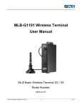
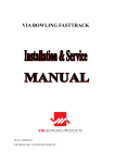
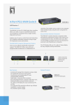
8-Port Switch
with Auto MDI/MDI-X
8 Port 10/100 Base-TX Switch
User Guide
Rev. AUG, 2002
1.
Introduction
Wellcome to the World of Mini-Networking.
In the modern business society, communication and sharing
information is crucial. Computer networks have proven to be one of
the fastest modes of communication.
The 8-Port Switch are compact and attractively designed for
desktop use. They are ideal solution for small office or SOHO
network user. The Switches provide wire-speed, Fast Ethernet
switching function that allows high-performance, low-cost
connection.
The Switches will automatically detect the speed of the device that
you plug into it to allow you to use both 10 and 100Mbps device.
They feature a store-and forward switching and it can auto-learn
and store source address on an 1K-entry MAC address for
respective and 1Mb Buffer.
Features
??Conforms to IEEE 802.3, 802.3u and 802.3x standard
??8-Port 10/100M Fast Ethernet Switch
??Auto MDI/MDI-X for cascading
??N-way auto-negotiation supported
??Half-duplex for backpressure, full-duplex for flow control
??Store-and-forward switching architecture
??1K-entry MAC address table for 8-Port Switch
??1Mb memory buffer sharing for 8-Port Switch
??LED indicators for Power, LK/ACT, FDX/COL, 100M
??External power supply
??164mm(W) x 100mm(D) x 26mm (H) Palm size
2
Package Contents
??8-Port Switch
??One DC power adapter
??User’s Guide
8TP Auto MDI/MDI-X Switch
Rubber Feet
DC power Adapter
Figure 1-2. Package Contents
User’s Guide
Compare the contents of your 8-Port Switch with the standard
checklist above. If any item is missing or damaged, please
contact your local dealer for service.
3
2.
Hardware Description
This section mainly describes the hardware of the 8-Port Switch.
The physical dimensions of the 5-Port Switch and 8-Port
Switch are the same : 164mm(W) X 100mm(D) x 26mm(H)
Front Panel
The LED indicators are located on the frond panel of the Switch.
They provide a real-time indication of systematic operation status.
The Front Panels 8-Port Switch are displayed in the following
figures.
LED Indicators
Power LED
Figure 2-2. The Front Panel of the 8-Port Switch
LED Indicators
4
The following table provides descriptions of the LED statuses
and their meaning.
LED
Status Color
Power
Description
On
Green
The power of the Switch is On
On
Green
The port is connecting with 100Mbps.
100Mbps
The connection between the Switch and
the device is 10Mbps, if the LINK/ ACT
light is on.
Off
On
LNK /ACT
The port is successfully connecting with
the device.
Green
Blinks
The port is receiving or transmitting data.
Off
On
FDX/COL
No device attached.
The port is operating in Full-duplex
mode.
Yellow
Collision of Packets occur s in the port.
Blinks
No device attached or in half-duplex
mode.
Off
Rear Panel
The Rear Panel of the 8-Port Switch consists of 8x 10/100 N-Way
UTP switch ports, and one DC power connector.
Figure 2-4. The Rear Panel of the 8-Port Switch
??RJ-45 Ports: 8x 10/100N-Way auto-sensing for 10Base-T
or 100Base-TX connection.
5
??Auto MDI/MDI-X: It can detect the cable straight connect
NIC or cascade to a hub or switch without change the
connector, the maximum distance between the Switch to
another device is 100 meters.
??DC Power Connector: Plug DC Power Adapter’s female
end into this device, and the male end of the DC Power
Adapter into a power outlet. The Adapter supply the Switch
with Voltage 9V, Current 800mA.
3.
Network Application
This section provides you a few examples of network topology in
which the 8-Port Switch is used, the Switch is design to be used
as a desktop or segment switch.
The switch automatically learns node address, which are
subsequently used to filter and forward all traffic based on the
destination address.
Stand Alone
The 8-Port Switch is designed to be a compact desktop size
switch which is a ideal solution for small workgroup. The Switch
can be used as a standalone switch to which personal computers,
server, printer server are directly connected to form small
workgroup.
6
Figure 3-1. Stand Alone Application
Enlarge Your Network
You can use Uplink port of the 8-Port Switch to connect with
another hub or switch to interconnect each of your small switched
workgroup to form a large switched network.
You can connect anyone switch port to hub or switch without
crossover cable by the Auto MDI/MDI-X function.
In the below illustration, two Switches are used to interconnect
two small workgroup. All the devices in this network can
communicate with each other. Connecting servers to the Switch
allow other users to access the server’s data.
7
Figure 3-2. Example of enlarging your network
8
4.
Trouble Shooting
The Switch can be easily monitored through panel indicators to
assist in identifying problems. This section describes common
problems you may encounter and where you can find possible
solutions.
??Diagnosing LED Indicators
IF Link indicator does not light up after making a connection.
You may check whether network interface (e.g., a network
adapter card on the attached device), network cable, or switch
port is defective or not. Be sure the cable is plugged into both
the Switch and corresponding device. Verified the proper
cable type is used and its length does not exceed specified
limits.
??Power
IF the power indicator does not turn on when the power cord is
plugged in, you may have a problem with power outlet, or
power cord. However, if the switch powers off after running for
a while, check for loose power connection, power loses or
surges at power outlet. If you still cannot resolve the problem,
contact your local dealer for assistance.
??Cabling
RJ-45 Ports: Use unshielded twisted-pair (UTP) or shield
twisted-pair (STP) cable for RJ-45 connections: 100O
Category 3,4 or 5 Cable for 10Mbps connections or 100O
Category 5 Cable for 100Mbps connections. Also be sure that
the length of any twisted-pair connection does not exceed 100
meters ( 328 feet ).
9
5.
Technical Specification
This section provides the specifications of the 5-Port Switch/
8-Port Switch :
Specification
Standards Compliance
IEEE 802.3 10BASE-T Ethernet,
IEEE 802.3u 100BASE-TX Fast Ethernet
ANSI/IEEE standard 802.3 N-Way auto-negotiation
Protocol
CSMA/CD
Max Forwarding Rate and
Max Filtering Rate
14,880 pps Ethernet port,
148,800 pps per Fast Ethernet port
LED Indicators
Per Port: Link/Activity, Full/Collision, 100M
Per Unit: Power
Network Cables
10Base-T: 2-pair UTP Cat. 3, 4, 5 cable (100m),
EIA/TIA-568 100-ohm STP (100m)
100Base-TX: 2-pair UTP Cat. 5 cable (100m),
EIA/TIA-568 100-ohm STP (100m)
Dimensions
164mm x 100mm x 26mm (W x D x H)
Operating Temperature
0ºC to 45ºC (32ºF to 113ºF)
Operating Humidity
10% to 90% (Non-condensing)
External Power Supply
DC 9V, 700mA
Power Consumption
4.2 Watt for 8-Port Switch
EMI
FCC Class A, CE Mark
Safety
UL
10
Federal Communications commission (FCC) Statement
This Equipment has been tested and found to comply with the limits for a
Class B digital device, pursuant to Part 15 of FCC rules. These limits are
designed to pro reasonable protection against harmful interference in a
residential installation. This equipments generates, uses and can radiate
radio frequency energy and, if not stalled and used in accordance with the
instruction, may cause harmful interference to radio communications.
However, there is no guarantee that interference will not occur in a
particular installation. If this equipment does cause harmful interference to
radio or television reception, which can be determined by turning the
equipment off and on, the user is encouraged to try to correct the
interference by one or more of the following measure:
-Reorient or relocate the receiving antenna.
-Increase the separation between the equipment and receiver.
-Connect the equipment into an outlet on a circuit different from that to
which the receiver is connected.
-Consult the dealer or an experienced radio/TV technician for help.
Warning:
[A shielded-type power cord is required in order to meet FCC emission
limits and also prevent interference to the nearby radio and television
reception. It is essential that only the supplied power cord be used.]
[Use only shielded cables to connect I/O device to this equipment.]
You are cautioned that changes or modifications not expressly approved
by the party responsible for compliance could void your authority to
operate the equipment.
11