1
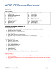
SALAMANDER INSTALLER GUIDE Salamander Installer Guide Introduction Salamander is a radio-controlled, battery-powered system for holding open fire doors. It combines ease and speed of installation with comprehensive safety features to make it suitable for installations meeting the A classification in the BS7273-4 code of practice. Before installing salamander, a thorough radio survey must be conducted using the purpose made Salamander Survey Kit. This will reveal how well radio signals pass between the planned positions for the controller and door holders. Any boosters needed to give the required coverage can be planned during the survey. Please read this document thoroughly before fitting your Salamander system. Salamander must only be used with a fire detection system installed to meet the requirements of BS 5839 L1, L2 or L3 otherwise extra smoke detection will be required either side of each door being held. Refer to BS 7273-4 for further details. Controller Mounting The mounting position for the controller should be decided when doing the radio survey. For good radio coverage, a position near the middle of the installation is usually best for mounting the controller. In practice, as the controller needs to be wired to the fire system, it is normal to site it close to the fire panel. Just follow a few simple rules when selecting a position: Mount at head height or above. Not in a corner or recess and at least 600 mm from a wall or similar surface. Never close to “noisy” electrical equipment, like switch mode power supplies or electric motors. At least 600 mm from heavy duty mains cables 1-11-9397 issue D SALAMANDER INSTALLER GUIDE Connecting to the Fire Panel Run mains power to the controller via an easily accessible isolation switch. Wiring must be in line with local fire regulations. Connect to the clearly marked mains terminals. The controller is connected to the building fire system so that it will be triggered when there is a fire condition or fault condition at the fire panel. It is supplied with a wire link from the RELAY terminal to the FIRE terminal and another wire link from the RELAY terminal to the FAULT terminal. These should be removed before making connections to the fire panel. The preferred method is to use a nominal 24V dc signal that is on in normal conditions and off when there is an alarm. Once this signal is interrupted, the controller will release the fire doors. In this way, a break or short circuit in the wiring will cause the door holders to fail-safe. The fault input to the controller should be connected to the fault output of the fire panel in the same way. This connection method is required to meet category A classification of BS7273-4. If the fault input is not used, its wire link to the relay terminal should be left in place as shown in the centre diagram. Alternatively, the controller can be connected to normally closed, volt-free relays on the fire panel or an auxiliary device as shown in the bottom diagram. The input trigger state can be inverted by selecting command code 05 (see Command Codes section) to suit normally open relays (note that this will invert the fault input as well as the fire input). This arrangement is not recommended as the controller will not fail safe if there is a wiring fault. It is good practice to check that if the power fails in the fire panel, any relay contacts used revert to a state where an alarm or fault is triggered at the Salamander Controller. This is a requirement for category A classification of BS7273-4. 1-11-9397 issue D SALAMANDER INSTALLER GUIDE Controller Commissioning Connect the back up battery, attach the front cover and switch on the mains supply. The controller will now automatically scan radio channels 0 to 13 and select the best for the installation. The number display shows the channel being checked while the three LEDs flash in a chasing pattern. When channel 13 is reached scanning is complete and the controller displays the channel it has selected for use and the background noise value. This complete process will take about 8 minutes. The controller should now display “OP” and the green power LED should be illuminated. If the controller displays AL or FA and flashes all LEDs, it is sensing an alarm / fault signal from the fire panel. Clear the alarm signal or check the wiring to the panel. Once the alarm /fault signal to the controller is cleared, press activate on the salamander controller to resume normal operation. If no green LED is lit then there is no mains power and the controller is working on backup battery power only. After 1 minute, the number display will switch off to conserve power. To indicate that the controller is still transmitting, a “t” will be displayed every 30 seconds. Enrolling Door Holders Each door holder has to be introduced to the controller so that they recognise each other. We call this enrolling. Enrol each door holder at the controller before fitting. To enrol, insert the batteries into the door holder while holding down the red release button. Once you hear the door holder motor running you can release the button. Wait for the motor to complete its test cycle (around 10 seconds) then press the Enrol button on the controller. AU is displayed on the controller. Wait for up to 15 seconds. When the enrol is complete the controller allocates the door a number. Note the number shown on the display and write it on the back of the door holder. The magnet will not turn on until the battery cover is fitted and the screw fully inserted. If enrol is not successful, the controller will display EE and lights all three LEDs. Remove the batteries and try again. Repeat this until all the door holders are enrolled. Once the door holder is enrolled the batteries can be removed ready for fitting. 1-11-9397 issue D SALAMANDER INSTALLER GUIDE Enrolling and Fitting Boosters Temporarily switch on the booster using its back-up battery and it will display “U r” to show it is unenrolled. Press the enrol button on the controller. The controller will display the first booster number as “r 1” and the next as “r 2” etc. Booster should be fitted before door holders to ensure good signal coverage. Refer to the full fitting instructions supplied with the booster. A radio survey must be performed before fitting boosters. Fitting Door Holders Door holders should be mounted at head height on the wall behind the door being held. Note that all Salamander door holders are now configured for horizontal mounting (see label on rear of holder). Fit near the edge of the door with the red release button facing outwards where it can be easily reached. The door holders should be fitted at head height or above. If the door does not open back to a wall, keeper plates on chains are available to bridge the gap. Alternatively, stands for mounting the door holder off the wall are available. Avoid mounting at a low level if at all possible, as the signal is less reliable at low level. Floor brackets for the door holder are available if there is no other solution, but this will attenuate the radio signal unpredictably. Fit the keeper plate in position on the door so that when the door is fully open, the plate makes contact with the door holder magnet face. Once the door holder is fitted, insert the batteries and replace the battery cover. The door holder will turn on within 30 seconds providing the controller and boosters are all active and not in an alarm state. Check that the door holds open. Press the red button and check that the door releases and closes. Do not leave doors held in an open position until the system has been tested. Commissioning and Fire Test Once all door holders are working, press Activate and check the controller for any warning messages. It may take some time for all warning messages to clear. For example, a system of 20 door holders it will take 11 minutes for the controller to check every unit. Note that any door holders enrolled but not being used will display a flashing low signal error and should be un-enrolled. Refer to the user guide for further details. Press the RELEASE button on the controller. All door holders should release within 30 seconds. After a further 30 seconds the doors holders will turn on again. Perform a fire test so that an alarm signal is sent from the fire panel to the controller. The controller should display “AL” and all doors should release within 30 seconds. Clear the alarm then press Activate to reset the controller. The controller should display “OP” Check the doors holders all turn on again after a further 30 seconds. 1-11-9397 issue D SALAMANDER INSTALLER GUIDE Trouble Shooting During Installation The controller displays “AL”, all 3 LEDs are flashing and the door holders will not turn on. The controller is registering an alarm signal from the fire panel. Check the connections to the fire panel. Should the controller release the doors on a high or low signal from the fire panel? This can be toggled by selecting command option 5 on the controller. After making changes, press Activate to clear the alarm. The controller displays “FA”, all 3 LEDs are flashing and the door holders will not turn on. The controller is registering a fault signal from the fire panel. Check the connections to the fire panel. If the controller fault input is not being used it should normally be linked to the REL(12V) terminal. If the controller is set to trigger on a high input from the fire panel (i.e. command option 5 has been used) then the link must be removed. After making changes, press Activate to clear the fault. All 3 LEDs are flashing, the 2 digit display is blank and the door holders will not turn on. The controller is registering a fault signal or a fire signal from the fire panel and the controller is running on back-up battery only. Check the connections to the fire panel as in the previous examples. After making changes, press Activate to clear the fault. I want to connect a timer to release all doors during the night time. This can be done using the fault input to the controller. Connect the timer relay between the FAULT terminal and the REL(12V) terminal at the controller. Use the same normally open or normally closed configuration as for the FIRE input. When the timer is triggered the controller will display “FA” and the doors will be released. They will stay released until the timer input switches back. Note that in the controller default setting there will be a 30 minute delay before the controller clears the “FA” display and the door holders switch back on - unless the Activate button is pressed. This can be changed by selecting command code option 08 and pressing release. The controller will then clear the “FA” display at the next 30 second broadcast. The door holders will not enrol to the controller, it just displays EE. Be sure to hold down the red button on the door holder when inserting the batteries. Then wait for the motor to finish running before pressing Enrol. The door holders should be enrolled at the controller before fitting. When I try to un-enrol, the controller displays EE. There are no door holders enrolled to the system. 1-11-9397 issue D SALAMANDER INSTALLER GUIDE Trouble Shooting During Use When I press a button on the controller it displays “Cd”. The keypad has been locked and the controller is prompting you to enter the security code. To unlock, refer to the “Locking the Keypad” section further on. If you do not know what code has been set, use the preset code 3142. Once the keypad is active, select command code option 00 and enter a new code 00 to disable the lock function. The number display on the controller is flashing The controller is in command mode. If no buttons are pressed the controller will time-out after 5 minutes and return to normal mode. Alternatively, use the up arrow (Enrol button) or down arrow (Activate button) to display 9 then press * (Release). The display will show the channel number being used by the controller and then exit command mode. There are no lights on the controller except a “t” every 30 seconds on the number display. The mains power has failed and the controller is running on its backup battery. After a fire test or false alarm, the controller displays “AL” and the doors will not hold. Press Activate to clear the alarm on controller, otherwise the alarm will automatically clear after 30 minutes. If this is inconvenient, the reset time can be reduced to zero by selecting command option 8 on the controller. Some doors keep releasing for no reason. The door holders in question are not receiving a consistent radio signal and are failing safe. This will also lead to premature battery failure. Conduct a radio survey and fit a booster. If the door holder is at floor level consider moving it to the top of the door. The controller is flashing the Low Signal LED but the door holder indicated is still working. A flashing low signal LED indicates that a status message has not been received from a door holder. The system will tolerate a certain level of missed messages and if the warning eventually clears by itself there is no cause for concern. The controller is showing a static Low Battery LED and a door holder number. The batteries in that door holder are beginning to run low. Replace the batteries. 1-11-9397 issue D SALAMANDER INSTALLER GUIDE Command Codes Press * RELEASE and Un enrol key at the same time to enter command codes. The number display flashes 00 to indicate command mode. Use the up and down arrows to select the code number then press * RELEASE. Note that the codes shown in the User Guide have been updated. The codes are now as follows: 00 Set key-lock code, see over page. 01 lock keypad now 02 (1 second broadcast – for radio surveys with survey kit only) 03 (4 second broadcast – for radio surveys with survey kit only) 04 standard broadcast interval 05 toggle fire/fault inputs – t L = trigger low (default value) / t H = trigger high 06 door holder statistics, see over page. 07 manual channel select (only when no door holders are enrolled) 08 fire/fault reset delay : 60 (30 minutes – default value) / 01 (30 seconds) 09 display channel number 10 toggle poll frequency: 1h (1 hour frequency) / 2h (2 hours - default value) 11 un-enrol booster 12 poll specified door holder for 10 minutes 13 development use only 14 display back-up battery condition 1-11-9397 issue D SALAMANDER INSTALLER GUIDE Locking the keypad 1) Select command code 00 and press * 2) A static “00” is now displayed 3) Decide on a security code number for unlocking the keypad. 4) Use the up and down arrows to select the first digit. 5) Press Un enrol and then select the second digit. Repeat as necessary 6) After entering the last digit press *. The keypad will now lock. Now any press of the keys other than Activate will show Cd on the display. Enter the security code as 4) to 6) above using the up and down arrows, Un enrol and *. OP will then be displayed. The key pad will lock itself again after 5 minutes of no use, or if command option 1 is selected. If the security code is lost or set by mistake, use the engineers unlock code 3142. To switch off key locking proceed as if to set a locking code and enter the new security code 00, i.e. complete steps 1) and 2) then press * again. Display Door Holder Statistics Enter command code 06 and press *. “01” is displayed. Use the up and down arrows to select the door holder number and press *. First the received signal strength at the door holder is displayed (63 maximum) Press *. Now the signal strength received at the controller is displayed (63 maximum) Press*. The battery strength is displayed (39 = max, 32 = min) Press*. The door holder node with which it is synchronised (0 = controller, 1-8 = booster number) Press*. The top 2 digits of the holder serial number Press*. The middle 2 digits of the serial number Press*. The last 2 digits of the serial number are displayed. Then either select another door holder or press Un enrol to return to OP. Help Desk 1-11-9397 issue D Tel: 01388 830909 or Email: salamander@geofire.co.uk SALAMANDER INSTALLER GUIDE Connecting a timer to release all doors during preset times. This can be done using the fault input to the controller. Connect the timer relay between the FAULT terminal and the REL(12V) terminal at the controller. Use the same normally closed configuration as for the FIRE input. When the timer is triggered and the relay contacts open, the controller will display “FA” and the doors will be released. They will stay released until the timer input switches on. Note that in the controller default setting there will be a 30 minute delay before the doors switch back on unless the Activate button is pressed. To remove the 30 minute reset delay, enter command mode, select option 08 and press release. This toggles the reset delay between 60 (30 minute delay, default setting) or 01 (no delay). With a 01 delay once the timer contacts close, the controller will reset at the next 32 second broadcast. Help Desk 1-11-9397 issue D Tel: 01388 830909 or Email: salamander@geofire.co.uk