1
Operating instructions
Solenoid Metering Pump
gamma/ L, GALa
P_G_0003_SW
Two sets of operating instructions are required for the safe, correct and proper operation of the metering pumps: The
product-specific operating instructions and the "General Operating Instructions for ProMinent® Solenoid Metering Pumps".
Both sets of operating instructions are only valid when read together.
Please carefully read these operating instructions before use! · Do not discard!
The operator shall be liable for any damage caused by installation or operating errors!
Technical changes reserved.
Part no. 987604
Original Operating Instructions (2006/42/EC)
BA G 033 09/11 EN
ProMinent Dosiertechnik GmbH
Im Schuhmachergewann 5-11
69123 Heidelberg
Germany
Telephone: +49 6221 842-0
Fax: +49 6221 842-617
email: info@prominent.com
Internet: www.prominent.com
987612, 1, en_GB
© 1999
2
Supplemental instructions
Supplementary information
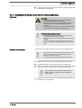
Read the following supplementary information in its entirety! Should you
already know this information, you have an even greater need of the Oper‐
ating Instructions.
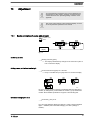
The following are highlighted separately in the document:
Fig. 1: Please read!
n
Enumerated lists
Instructions
ð Outcome of the instructions
Information
This provides important information relating to the correct
operation of the device or is intended to make your work
easier.
Safety notes
Safety notes are identified by pictograms - see Safety Chapter.
General user instructions
Two sets of operating instructions are required for the safe, correct and
proper operation of the metering pumps: The product-specific operating
instructions and the "General Operating Instructions for ProMinent Sole‐
noid Metering Pumps."
Both sets of operating instructions are only valid when read together.
Please read these operating instructions carefully before use! Do not dis‐
card!
State the identity code and serial number
Please state identity code and serial number, which you can find on the
nameplate when you contact us or order spare parts. This enables the
device type and material versions to be clearly identified.
General non-discriminatory approach
In order to make it easier to read, this document uses the male form in
grammatical structures but with an implied neutral sense. It is aimed
equally at both men and women. We kindly ask female readers for their
understanding in this simplification of the text.
3
Table of contents
Table of contents
1
Identity code.................................................................................... 6
2
About this pump............................................................................... 8
3
Safety chapter................................................................................. 9
4
Storage, transport and unpacking................................................. 14
5
Overview of equipment and control elements............................... 16
5.1 Overview of equipment.........................................................
5.2 Control elements...................................................................
5.2.1 Key functions......................................................................
5.2.2 Stroke length adjustment knob...........................................
5.2.3 Control elements................................................................
6
Functional description.................................................................... 19
6.1 Liquid End.............................................................................
6.2 Drive Unit..............................................................................
6.3 Capacity................................................................................
6.4 Self-Bleeding.........................................................................
6.5 Functional description of control...........................................
6.5.1 Operating modes, functions, options..................................
6.5.2 Function and fault indicator................................................
6.5.3 Hierarchy of operating modes, functions and fault sta‐
tuses...................................................................................
19
19
19
19
19
19
21
21
7
Assembly....................................................................................... 22
8
Installation, hydraulic..................................................................... 23
8.1 Install hose lines....................................................................
8.1.1 Installation for metering pumps without bleed valve..........
8.1.2 Installation for metering pumps with bleed valve...............
8.1.3 Installation for metering pumps with self-bleeding (SEK
type)...................................................................................
9
10
24
24
26
27
Installation, electrical..................................................................... 29
9.1 Supply voltage connector......................................................
9.2 Description of the sockets.....................................................
9.2.1 "External control" terminal..................................................
9.2.2 "Level Switch" terminal.......................................................
9.2.3 "Dosing monitor" terminal...................................................
9.2.4 Relay..................................................................................
30
31
31
32
32
33
Adjustment..................................................................................... 35
10.1 Basic principles of pump adjustment...................................
10.2 Checking adjustable values................................................
10.3 Changing to adjustment mode............................................
10.4 Operating mode selection (MODE menu)...........................
10.5 Operating mode settings (SET menu).................................
10.5.1 "Manual" operating mode settings...................................
10.5.2 "Analog" operating mode settings (ANALG menu)..........
10.5.3 "Contact" operating mode settings (CNTCT menu).........
10.5.4 "Batch" operating mode settings (BATCH menu)............
10.6 Programmable function settings (SET menu )....................
10.6.1 “Calibrate” function settings (CALIB menu)......................
10.6.2 “Pressure ratings” function settings (PRESS menu)........
10.6.3 “Auxiliary frequency” function settings (AUX menu).........
10.6.4 “Flow” function settings (FLOW menu)............................
10.7 Setting the code (CODE menu)..........................................
10.8 Deleting the total number of strokes or total litres (CLEAR
window)...............................................................................
4
16
17
17
18
18
35
36
36
37
38
38
38
41
43
43
44
45
46
46
46
47
Table of contents
11
Operation....................................................................................... 48
11.1 Manual operation................................................................ 48
11.2 Remote operation................................................................ 50
12
Maintenance.................................................................................. 51
13
Repairs.......................................................................................... 53
13.1 Cleaning valves................................................................... 53
13.2 Replacing the metering diaphragm..................................... 55
14
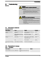
Troubleshooting............................................................................. 59
14.1 Faults without a fault alert...................................................
14.2 Faults with error message...................................................
14.2.1 Fault alerts.......................................................................
14.2.2 Warning Alerts..................................................................
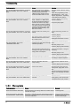
14.3 All Other Faults...................................................................
59
59
59
60
61
15
Decommissioning.......................................................................... 62
16
Technical data............................................................................... 64
16.1 Performance data................................................................
16.2 Accuracy.............................................................................
16.2.1 Standard Liquid End.........................................................
16.2.2 Self-Bleeding Liquid End..................................................
16.3 Viscosity..............................................................................
16.4 Material specifications.........................................................
16.5 Electrical data......................................................................
16.6 Temperatures......................................................................
16.7 Climate................................................................................
16.8 Protection class and Safety Requirements.........................
16.9 Compatibility........................................................................
16.10 Sound pressure level........................................................
16.11 Shipping weight.................................................................
64
65
65
65
65
66
66
66
67
67
67
68
68
17
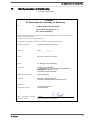
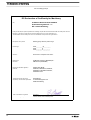
EC Declaration of Conformity........................................................ 69
18
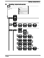
Operating / adjustment overview................................................... 71
19
Continuous displays...................................................................... 73
20
Index.............................................................................................. 74
5
Identity code
1
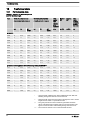
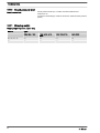
Identity code
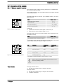
Product range gamma/ L
GALa
Type
Performance
bar
l/h
1000
10
0.74
1601
16
1.1
1602
16
2.1
1005
10
4.4
0708
7
7.1
0413
4
12.3
0220
2
19.0
1605
16
4.1
1008
10
6.8
0713
7
11.0
0420
4
17.1
0232
2
32.0
Solenoid Ø 70 / M70
Solenoid Ø 85 / M85
Material version
PPE
Polypropylene / EPDM
PPB
Polypropylene / FPM
NPE
Clear acrylic / EPDM
NPB
Clear acrylic / FPM
PVT
PVDF / PTFE
TTT
PTFE/PTFE
SST
Stainless steel 1.4571 / PTFE
Dosing head version
0
without bleed valve, without valve spring only for NP, TT and SS
1
without bleed valve, with valve spring only for NP, TT and SS
2
with bleed valve, without valve spring only for PP, NP, PV, not for type 0232
3
with bleed valve, with valve spring only for PP, NP, PV, not for type 0232
4
without bleed valve, with valve spring for more highly viscous media
9
self-bleeding only for PP and NP, not for types 1000 and 0232
Hydraulic connector
0
Standard connector in line with technical data
5
Connector for 12/6 tube, discharge side only
9
Connector for 10/4 tube, discharge side only
Design
0
with ProMinent logo
Power supply
6
U
100 - 230 V, ±10 %, 50/60 Hz
M
12 ... 24 V DC (M 70 only)
N
24 V DC (M 85 only)
Identity code
Product range gamma/ L
P
24 V AC
Cable and plug
A
2 m European
B
2 m Swiss
C
2 m Australian
D
2 m USA
1
2 m open end
Relay
0
No relay
1
fault indicating relay (NC) (change-over relay)
3
fault indicating relay (NO) (change-over relay)
4
as 1 + pacing relay, (per 1x ON)
5
as 3 + pacing relay, (per 1x ON)
Accessories
0
No accessories
1
with foot and injection valve, 2 m PVC suction
line, 5 m PE metering line, only for PP, PC and
NP
2
as 0 + calibration cylinder
3
as 1 + calibration cylinder
Control versions
0
Manual + external 1:1
1
Manual + external with pulse control
2
Manual + external 1:1 + analog current
3
Manual + external with pulse control +
analog current
4
as 0 + timer
5
as 3 + timer
P
as 3 + PROFIBUS®
Access code
0
no access code
1
with access code
Dosing monitor
0
Input for pulses
1
Input for continuous contact
Pause / level
0
Pause N/C, level N/C
7
About this pump
2
About this pump
Pumps in the ProMinent gamma/ L product range are microprocessor-con‐
trolled solenoid metering pumps with the following characteristics:
n
n
n
n
n
n
The capacity can be displayed in l/h or gal/h respectively (in a cali‐
brated state or in strokes/min
The stroke length is infinitely adjustable and is shown in the LCD dis‐
play
The stroke rate can be set digitally precisely and is shown in the LCD
display
The rated pressure of the gamma/ L can be adapted by pressure rat‐
ings to a system
Two pumps can be actuated differently by means of the same
standard signal
Large illuminated LCD display
The hydraulic parts of the gamma/ L are identical to those of the Beta®.
8
Safety chapter
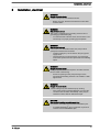
3
Safety chapter
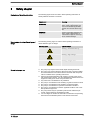
Explanation of the safety information
Warning signs denoting different types of
danger
The following signal words are used in these operating instructions to
identify different severities of a hazard:
Signal word
Meaning
WARNING
Denotes a possibly hazardous sit‐
uation. If this is disregarded, you
are in a life-threatening situation
and this can result in serious inju‐
ries.
CAUTION
Denotes a possibly hazardous sit‐
uation. If this is disregarded, it
could result in slight or minor inju‐
ries or material damage.
The following warning signs are used in these operating instructions to
denote different types of danger:
Warning signs
Type of danger
Warning – automatic start-up.
Warning – high-voltage.
Warning – danger zone.
Correct and proper use
n
n
n
n
n
n
n
n
n
n
The pump may only be used to meter liquid metering chemicals.
The pump may only be started up after it has been correctly installed
and commissioned in accordance with the technical data and specifi‐
cations contained in the operating instructions.
Observe the general limitations with regard to viscosity limits, chem‐
ical resistance and density - see also ProMinent® resistance list in the
equipment catalogue or under www.prominent.com!
Any other uses or modifications are prohibited.
The pump is not intended for the metering of gaseous media or solids.
The pump is not intended for the metering of explosive media.
The pump is not intended for operation in hazardous locations.
The pump is not intended for exterior applications without use of suit‐
able protective equipment.
The pump should only be operated by trained and authorised per‐
sonnel, see the following "Qualifications" table.
You are obliged to observe the information contained in the operating
instructions at the different phases of the device's service life.
9
Safety chapter
Safety notes
WARNING!
Warning about personal and material damage
The pump can start to pump, as soon as it is connected to
the mains voltage.
–
Install an emergency cut-off switch in the pump power
supply line or integrate the pump in the emergency cutoff management of the system.
WARNING!
Danger of electric shock
A mains voltage may exist inside the pump housing.
–
If the pump housing has been damaged, you must dis‐
connect it from the mains immediately. It may only be
returned to service after an authorised repair.
WARNING!
Fire danger
Combustible media may only be transported using stainless
steel dosing heads. In exceptional cases where this is not
possible, PTFE with carbon can be used, whereby our TT_
versions are manufactured from this conducting plastic.
Here, the operator is urged to take special care due to the
low mechanical strength.
WARNING!
Warning of hazardous or unknown feed chemical
Should a hazardous or unknown feed chemical be used, it
may escape from the hydraulic components when working
on the pump.
–
–
Take appropriate protective measures before working on
the pump (protective eyewear, protective gloves, ...).
Read the safety data sheet on the feed chemical.
Drain and flush the liquid end before working on the
pump.
WARNING!
Danger from hazardous substances!
Possible consequence: Fatal or very serious injuries.
Please ensure when handling hazardous substances that
you have read the latest safety data sheets provided by the
manufacture of the hazardous substance. The actions
required are described in the safety data sheet. Check the
safety data sheet regularly and replace, if necessary, as the
hazard potential of a substance can be re-evaluated at any
time based on new findings.
The system operator is responsible for ensuring that these
safety data sheets are available and that they are kept up to
date, as well as for producing an associated hazard assess‐
ment for the workstations affected.
10
Safety chapter
CAUTION!
Warning of feed chemical spraying around
Feed chemical can spray out of the hydraulic components if
they are manipulated or opened due to pressure in the liquid
end and adjacent parts of the system.
–
–
Disconnect the pump from the mains power supply and
ensure that it cannot be switched on again by unauthor‐
ised persons.
Depressurise the system before commencing any work
on hydraulic parts.
CAUTION!
Warning of feed chemical spraying around
An unsuitable feed chemical can damage the parts of the
pump contacted by the chemical.
–
Take into account the resistance of the material con‐
tacted by the chemical when selecting the feed chemical
- refer to ProMinent® resistance list in the equipment
catalogue or under www.prominent.com.
CAUTION!
Warning of feed chemical spraying around
The metering pump can generate a multiple of its rated pres‐
sure. If a discharge line is blocked, hydraulic parts may burst.
–
Correctly install a relief valve in the discharge line down‐
stream of the metering pump.
CAUTION!
Danger of personnel injury and material damage
The use of untested third party parts can result in personnel
injuries and material damage.
–
Only fit parts to metering pumps, which have been
tested and recommended by ProMinent.
CAUTION!
Danger from incorrectly operated or inadequately maintained
pumps
Danger can arise from a poorly accessible pump due to
incorrect operation and poor maintenance.
–
–
Ensure that the pump is accessible at all times.
Adhere to the maintenance intervals.
CAUTION!
Danger from incorrect metering
Should a different liquid end size be fitted, this will change
the metering behaviour of the pump.
–
Have the pump reprogrammed in the works.
11
Safety chapter
CAUTION!
Warning of illegal operation
Observe the regulations that apply where the unit is to be
installed.
Fixed separating protective equipment
n
n
n
Dosing head
Housing
Hood (houses the control elements)
The dosing head may only be removed by the customer in accordance
with the "Repair" chapter.
The housing and the hood may only be removed by ProMinent customer
service department.
Information in the event of an emergency
In an emergency, either pull out the mains plug or press the customer
installed emergency-off switch or disconnect the pump according to the
emergency-off management for your system!
If feed chemical escapes, also depressurise the hydraulic system around
the pump. Adhere to the safety data sheet for the feed chemical.
Qualification of personnel
Activity
Qualification level
Storage, transport, unpacking
Instructed person
Assembly, installation of hydraulic
system
Technical personnel, service
Installation, electrical
Electrical technician
Operation
Instructed person
Maintenance, repair
Technical personnel, service
Decommissioning, disposal
Technical personnel, service
Troubleshooting
Technical personnel, electrical
technician, instructed person,
service
Explanation of the terms:
Technical personnel
A qualified employee is deemed to be a person who is able to assess the
tasks assigned to him and recognise possible dangers based on his/her
technical training, knowledge and experience, as well as knowledge of
pertinent regulations.
Note:
A qualification of equal validity to a technical qualification can also gained
by several years employment in the relevant work area.
Electrical technician
Electrical technicians are deemed to be people, who are able to complete
work on electrical systems and recognize and avoid possible dangers
independently based on their technical training and experience, as well as
knowledge of pertinent standards and regulations.
Electrical technicians should be specifically trained for the working envi‐
ronment in which the are employed and know the relevant standards and
regulations.
Electrical technicians must comply with the provisions of the applicable
statutory directives on accident prevention.
Instructed person
12
Safety chapter
An instructed person is deemed to be a person who has been instructed
and, if required, trained in the tasks assigned to him/her and possible dan‐
gers that could result from improper behaviour, as well as having been
instructed in the required protective equipment and protective measures.
Customer Service department
Customer Service department refers to service technicians, who have
received proven training and have been authorised by ProMinent or Pro‐
Maqua to work on the system.
Sound pressure level
Sound pressure level LpA < 70 dB in accordance with EN ISO
20361:2010-10
at maximum stroke length, maximum stroke rate, maximum back pressure
(water)
13
Storage, transport and unpacking
4
Storage, transport and unpacking
Safety information
WARNING!
The transporting of pumps which have been used with radio‐
active feed chemicals is forbidden!
They will also not be accepted by ProMinent!
WARNING!
Only return the metering pump for repair in a cleaned state
and with a flushed liquid end - refer to the section on decom‐
missioning!
Only send metering pumps with a filled in Decontamination
Declaration form. The Decontamination Declaration consti‐
tutes an integral part of an inspection / repair order. A unit
can only be inspected or repaired if a Decontamination Dec‐
laration is submitted that has been completed correctly and
in full by an authorised and qualified person on behalf of the
pump operator.
The "Decontamination Declaration" form can be found in the
General Operating Instructions or under
www.prominent.com.
CAUTION!
Danger of material damage
The device can be damaged by incorrect or improper storage
or transportation!
–
–
–
The unit should only be stored or transported in a well
packaged state - preferably in its original packaging.
The packaged unit should also only be stored or trans‐
ported in accordance with the stipulated storage condi‐
tions.
The packaged unit should be protected from moisture
and the ingress of chemicals.
Personnel:
Ambient conditions
Technical personnel
Data
Value Unit
Minimum storage and transport tempera‐
ture
-10 °C
Maximum storage and transport tempera‐
ture
+50 °C
Air humidity
< 95 % rel.
humidity*
* non-condensing
14
n
Storage, transport and unpacking
Scope of supply
Compare the delivery note with the scope of supply:
n
n
n
n
n
Metering pump with mains power cable
Connector kit for tube/pipe connection
Product-specific operating instructions with EC Declaration of Con‐
formity
CD with order information, exploded diagrams, performance diagrams
and data sheets
Optional accessories if ordered
15
Overview of equipment and control elements
5
Overview of equipment and control elements
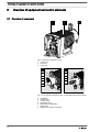
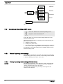
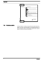
5.1 Overview of equipment
1
2
3
P_G_0026_SW
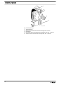
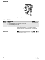
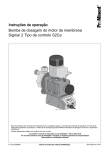
Fig. 2: Overview of equipment, total
1
2
3
Control unit
Drive unit
Liquid end
3.1
3.2
a
a
d
e
b
b
f
d
g
c
c
P_G_0027_SW
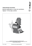
Fig. 3: 3.1 Liquid end with bleed valve, 3.2 Self-bleeding liquid end (SEK)
a
b
g
d
e
f
g
16
Backplate
Dosing head
Suction valve
Discharge valve
Bleed valve, self-bleeding
Bleed valve
Bypass hose nozzle, concealed
Overview of equipment and control elements
5.2 Control elements
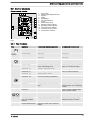
Control elements, overview
8
1
2
3
4
5
6
7
8
9
10
11
12
13
9 10
1
2
3
4
7
5
6
LCD screen
Stroke length adjustment knob
[UP] key
[P] key
[DOWN] key
[STOP/START] key
[ i ] key
Fault indicator (red)
Warning indicator (yellow)
Operating indicator (green)
"Dosing monitor" terminal
"External control" terminal
"Level Switch" terminal
11
12
13
P_G_0006_SW
Fig. 4
5.2.1 Key functions
Key
Application
In continuous displays (operation)
In adjustment mode (set up)
Pressed briefly
Stop pump,
Stop pump,
start pump
start pump
Pressed briefly
Start batch (only in ‘Batch’ operating
mode), acknowledge fault
Confirm entry - jump to next menu
point or to continuous display
Pressed for 2 s
Change to adjustment mode
-
Pressed for 3 s
-
Jump to continuous display
Pressed for 10 s
Display software version
-
Pressed for 15 s
Load factory settings (calibration)
-
Pressed 1x
Change between the continuous dis‐
plays
Change between "Changing indi‐
vidual numbers" and "Changing a
number"
Pressed 2x
-
Under "change individual digits":
jump to the first number
Individually pressed
(until ‘Set’ identifier
appears)
Change directly changeable variables
Select another setting, change
individual number or number
Pressed simultaneously
Priming (in "Stroke rate" continuous
display)
-
STOP
START
[STOP/
START]
P
[P]
i
B0098
[i]
[UP], [DOWN]
17
Overview of equipment and control elements
5.2.2 Stroke length adjustment knob
The stroke length can be adjusted using the stroke length adjustment knob
and with it the volume per stroke.
5.2.3 Control elements
Familiarise yourself with the pump control elements using the
"Control elements and key functions" overview!
Identifiers
The LCD screen supports the operation and adjustment of the pump with
different identifiers:
Stop Aux Pause Error
Mem
Calib
Flow
Set
B0081
Fig. 5
The identifiers have the following meanings:
Identifiers
P
Meaning
The pump is in adjustment mode.
In the continuous display: Security lock (if a code was set).
In adjustment mode: Indicates entry into ‘CODE’ menu.
‘Stop’
The pump was stopped using the [STOP/START] key.
‘Aux’
The pump is currently pumping with the auxiliary rate as the stroke rate.
‘Pause’
In the ‘AUX’ menu. The pump is in the ‘AUX’ menu.
‘Error’
The pump was externally stopped by the "Pause" function (externally).
‘Mem’
In "Contact" and "Batch" operating modes: The auxiliary function "Memory" has been set.
In the ‘CNTCT’ or ‘BATCH’ menu (identifier ‘Mem’ flashes): The auxiliary function "Memory"
can be set.
‘Calib’
The pump is in the ‘CALIB’ menu.
In the continuous display (identifier ‘Calib’ flashes): Deviations of the stroke length from the
value to the time of calibration by more than 10 scale divisions, that is with a stroke length of 40
%, if this is set at less than 30 % or at greater than 50 %.
‘Flow’
The pump is in the ‘FLOW’ menu.
‘Set’
The pump is in the ‘SET’ menu.
The number of strokes achieves is higher than the maximum figures of 99999 that can be dis‐
played in the LCD screen.
The pump only shows the metering volume and the capacity
in the calibrated state in l or l/h or in gal or gal/h.
18
Functional description
6
Functional description
6.1 Liquid End
The dosing process is performed as follows: The diaphragm is pressed
into the dosing head; the pressure in the dosing head closes the suction
valve and the feed chemical flows through the discharge valve out of the
dosing head. The diaphragm is now drawn out of the dosing head; the dis‐
charge valve closes due to the negative pressure in the dosing head and
fresh feed chemical flows through the suction valve into the dosing head.
One cycle is completed.
6.2 Drive Unit
The diaphragm is driven by an electromagnet, which is controlled by an
electronic controller.
6.3 Capacity
The capacity is determined by the stroke length and the stroke rate. The
stroke length can be adjusted between 0 and 100 % using the stroke
length adjustment knob. A metering volume of between 30 to 100% is
reproduced as being technically sensible (SEK type: 50 - 100 %)! The
stroke rate can be set using the arrow keys (not in "Analog" operating
mode) within a range of 0 - 180 strokes/min.
6.4 Self-Bleeding
Self-bleeding liquid ends (SEK types) are capable of independent priming
when a discharge line is connected and diverting existent air pockets via a
bypass. During operation they are also capable of conveying away gases
which are produced, independently of the operating pressure in the
system. It is also possible to dose precisely in a depressurised state due
to the integral back pressure valve.
6.5 Functional description of control
6.5.1 Operating modes, functions, options
Operating modes
The operating modes are selected via the ‘MODE’ menu (dependent on
the identity code, some operating modes may not be present):
‘Analog’ operating mode (Identity code, control variant: analog). The
stroke rate is controlled using an analog current signal via the "External
control" terminal Processing of the current signal can be preselected via
the control unit.
‘Manual’ operating mode The stroke rate is set manually via the control
unit. 100 % corresponds to 180 strokes/min.
‘Contact’ operating mode: This operating mode provides the option of
making fine adjustments using small scaling or transfer factors. The
metering can be triggered either by a pulse received via the "External con‐
trol" terminal or through a contact or a semiconductor switching element. A
metering quantity (batch) or a number of strokes (scaling or transfer factor
0.01 to 99.99) can be pre-selected via the control unit using the "Pulse
Control" option.
19
Functional description
‘Batch’ operating mode: This operating mode provides the option of
working with large transfer factors (up to 65535). The metering can be trig‐
gered either by pressing the [P] key or by a pulse received via the
"External control" terminal or through a contact or a semiconductor
switching element. It is possible to pre-select a metering quantity (batch)
or a number of strokes via the control unit.
‘BUS’ operating mode (Identity code, control variant: CANopen or PRO‐
FIBUS® This operating mode provides the option of controlling the pump
via a BUS (see “Supplementary instructions for ProMinent® gamma/ L and
ProMinent Sigma versions with PROFIBUS®".
Functions
The following functions can be selected using the SET menu:
"Calibrate" function: (Identity code, stroke length adjustment: Manual +
calibration): The pump can also be operated in the calibrated state in all
operating modes. In this case, the corresponding continuous displays can
then indicate the metering volume or the capacity directly. Calibration is
maintained within a stroke rate range of 0 - 180 strokes/min. The calibra‐
tion is also maintained when the stroke length is altered by up to ±10 %
scale divisions.
"Auxiliary frequency" function: Enables a freely selectable and program‐
mable stroke rate to be switched on in the ‘SET’ menu, which can be con‐
trolled via the "External Control" terminal. This auxiliary frequency has pri‐
ority over the operating mode stroke rate settings.
"Flow" function: Stops the pump when the flow is insufficient, provided a
dosing monitor is connected. The number of defective strokes, after which
the pump is switched off, can be set in the ‘SET’ menu.
The following functions are available as standard:
"Level switch" function: Information about the liquid/powder level in the
chemical feed container is reported to the pump control. To do so, a twostage level switch must be fitted; it is connected to the "Level switch" ter‐
minal.
"Pause" function: The pump can be remotely stopped via the "External
Control" terminal. The "Pause" function only works via the "External Con‐
trol" terminal.
The following functions are triggered by a key press:
"Stop" function: The pump can be stopped without disconnecting it from
the mains/power supply by pressing the [STOP/START] key.
"Priming" function: Priming (short-term transport at maximum frequency)
can be triggered by simultaneous pressing of the two arrow keys in the
"Stroke rate" continuous display.
Relay option
20
The pump has two connecting options (not with PROFIBUS® or timer):
Functional description
Option "Fault indicating relay" or "Output relay": In the event of fault sig‐
nals, warning signals or tripped level switches, the relay connects to com‐
plete an electric circuit (for alarm horns etc.). The relay can be retrofitted
via a knock-out in the drive unit.
"Fault indicating and pacing relay" option In addition to the fault indicating
relay, the pacing relay can be used to make a contact every stroke. The
relay can be retrofitted via a knock-out in the drive unit.
6.5.2 Function and fault indicator
The operating and fault statuses are indicated by the three LED indicators
and the ‘Error’ identifier on the LCD screen, see also the "Trouble‐
shooting" chapter.
LCD screen
If a fault occurs, the identifier ‘Error’ appears and an additional error mes‐
sage.
LED displays
Operating indicator (green): The operating indicator illuminates if during
pump operation there are no incoming fault or warning messages. It goes
out briefly with every stroke.
Warning indicator (yellow): The warning indicator illuminates if the pump
electronics detect a condition which may lead to a fault, e.g. "liquid level
low 1st stage".
Fault indicator (red): The fault indicator illuminates if a fault occurs e.g.
liquid level low 2nd stage".
6.5.3 Hierarchy of operating modes, functions and fault statuses
The different operating modes, functions and fault statuses have a dif‐
ferent effect on if and how the pump reacts.
The following list shows the order:
1. - Priming
2. - Fault, Stop, Pause
3. - Auxiliary frequency (external frequency changeover)
4. - Manual, external contact
Comments:
re 1 - "Priming" can take place in any mode of the pump (providing it is
functioning).
re 2 - "Fault", "Stop" and "Pause" stop everything apart from "Priming".
re 3 - The stroke rate of "Auxiliary rate" always has priority over the
stroke rate specified by an operating mode or priority 4.
21
Assembly
7
Assembly
WARNING!
Risk of electric shock
If water or other electrically conducting liquids penetrate into
the drive housing, an electric shock may occur.
–
Position the pump so that drive housing cannot be
flooded.
CAUTION!
Danger from incorrectly operated or inadequately maintained
pumps
Danger can arise from a poorly accessible pump due to
incorrect operation and poor maintenance.
–
–
Ensure that the pump is accessible at all times.
Adhere to the maintenance intervals.
Capacity too low
The liquid end valves can be disrupted by vibrations.
–
Secure the metering pump so that no vibrations can
occur.
Capacity too low
If the valves of the liquid end do not stand vertically upwards,
they cannot close correctly.
–
Suction and discharge valves must stand vertically
upwards (for self-bleeding liquid end, the bleed valve).
Mount the metering pump with the pump foot on a horizontal, level
and load-bearing supporting surface.
22
Installation, hydraulic
8
Installation, hydraulic
Safety notes
CAUTION!
Warning of feed chemical spraying around
An unsuitable feed chemical can damage the parts of the
pump contacted by the chemical.
–
Take into account the resistance of the material con‐
tacted by the chemical when selecting the feed chemical
- refer to ProMinent® resistance list in the equipment
catalogue or under www.prominent.com.
CAUTION!
Warning of feed chemical spraying around
Pumps which are not fully installed hydraulically can eject
feed chemicals from the outlet openings of the discharge
valves as soon as they are connected to the mains.
–
–
The pump must first be hydraulically installed and then
electrically.
In the event that you have failed to do so, press the
[STOP/START] button or press the emergency-stop
switch.
CAUTION!
Warning of feed chemical spraying around
Feed chemical can spray out of the hydraulic components if
they are manipulated or opened due to pressure in the liquid
end and adjacent parts of the system.
–
–
Disconnect the pump from the mains power supply and
ensure that it cannot be switched on again by unauthor‐
ised persons.
Depressurise the system before commencing any work
on hydraulic parts.
CAUTION!
Danger from rupturing hydraulic components
Peak loads during the dosing stroke can cause the maximum
permissible operating pressure of the system and pump to
be exceeded.
–
The discharge lines are to be properly designed.
CAUTION!
Danger of personnel injury and material damage
The use of untested third party parts can result in personnel
injuries and material damage.
–
Only fit parts to metering pumps, which have been
tested and recommended by ProMinent.
CAUTION!
Warning of illegal operation
Observe the regulations that apply where the unit is to be
installed.
23
Installation, hydraulic
8.1 Install hose lines
8.1.1 Installation for metering pumps without bleed valve
Safety notes
CAUTION!
Warning of feed chemical spraying around
If the pipes are improperly installed, they can come lose or
burst.
–
–
–
Route all hose lines so they are free from mechanical
stresses and kinks.
Only use original hoses with the specified hose dimen‐
sions and wall thicknesses.
To ensure high durability of the connections, only use
clamp rings and hose nozzles that are intended for the
hose diameter in question.
CAUTION!
Danger resulting from rupturing hydraulic components
Hydraulic components can rupture if the maximum permis‐
sible operating pressure is exceeded.
–
–
–
Always maintain the maximum permissible operating
pressure of all hydraulic components - please refer to
the product specific operating instructions and system
documentation.
Never allow the metering pump to run against a closed
shut-off device.
Install a relief valve.
CAUTION!
Hazardous feed chemicals can escape
Hazardous or extremely aggressive feed chemicals can leak
out when using conventional bleeding procedures with
metering pumps.
–
Install a bleed line with recirculation into the storage
tank.
CAUTION!
Hazardous feed chemicals can escape
Hazardous or extremely aggressive feed chemicals can leak
out in the event that the metering pump is removed from the
installation.
–
Shut-off valves must be installed on the metering pump's
pressure and discharge sides.
CAUTION!
Uncontrolled flowing feed chemicals
Feed chemicals can leak through a stopped metering pump
in the event of back pressure.
–
24
For this purpose, use an injection valve or vacuum
breaker.
Installation, hydraulic
CAUTION!
Uncontrolled flowing feed chemicals
Feed chemicals can leak through the metering pump in an
uncontrolled manner in the event of excessive priming pres‐
sure.
–
The maximum priming pressure for the metering pump
may not be exceeded - please refer to the product-spe‐
cific operating instructions.
The pipes are to be aligned in such a way as the metering
pump and the liquid end can be removed from the side, if
necessary.
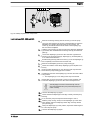
Install hose lines - design PP, NP, PV, TT
1.
Cut off the ends of the hoses at right angles.
2.
Pull the union nut (2) and clamp ring (3) over the tube (1) - see
figure Fig. 6.
3.
Push the tube end (1) up to the stop over the nozzle (4). Widen it, if
necessary.
Ensure that the O-ring and flat seal (5) is properly
fitted to the valve (6).
Used PTFE seals may never be re-used. An installa‐
tion sealed in this way will not be watertight.
The reason for this is that this type of seal is perma‐
nently distorted when subjected to pressure.
In order to enable it to be distinguished from the
EPDM flat seal, the FPM flat seal design PV has a dot.
4.
Place the tube (1) with the nozzle (4) onto the valve (6).
5.
Clamp the hose connector: Screw the union nut (2) tight while
simultaneously pressing on the tube (1).
6.
Re-tighten the hose connector: Pull on the hose (1) briefly, which is
fastened to the dosing head, and tighten up the union nut (2) once
more.
25
Installation, hydraulic
1
2
3
4
5
6
1
2
3
4
Tube
Union nut
Clamp ring
Nozzle
O-ring and flat seal
Valve
5
6
P_MAZ_0021_SW
Fig. 6: Designs PP, NP, PV, TT
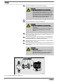
Installing stainless steel pipe - design SS
1.
Pull the union nut (2) and clamp rings (3, 4) over the pipe (1) with
approx. 10 mm overhang - see Fig. 7.
2.
Insert the pipe (1) up to the stop in the valve (5).
3.
Tighten the union nut (2).
1
2
3
4
5
1
2
3
Pipe
Union nut
Rear clamp ring
Front clamp ring
Valve
4
5
P_MAZ_0022_SW
Fig. 7: Design SS
Installing hose lines - design SS
CAUTION!
Warning of feed chemical spraying around
Connections can come free in the event that hose lines are
installed incorrectly on stainless steel valves.
–
–
Only use PE or PTFE hose lines.
In addition, insert a stainless steel support insert into the
hose line.
8.1.2 Installation for metering pumps with bleed valve
Safety notes
CAUTION!
– All of the installation and safety notes for metering
pumps without bleed valves also apply.
Installation of the return line
26
A return line is connected in addition to the suction and discharge lines.
1.
Fasten the tube line to the return line tube nozzle or to the liquid end
bleed valve. PVC tube, soft, 6x4 mm is recommended for this.
2.
Feed the free end of the return line back to the storage tank.
Installation, hydraulic
3.
Shorten the return line hose so that it cannot submerge into the feed
chemical in the storage tank.
8.1.3 Installation for metering pumps with self-bleeding (SEK type)
Safety notes
CAUTION!
– All of the installation and safety notes for metering
pumps without self-bleeding also apply.
– The maximum values for priming lift, priming pressure
and the viscosity of the feed chemical may not be
exceeded.
– The suction end hose line cross section may not exceed
the hose line cross section of the suction valve.
Information about priming pressure
– The priming pressure on the suction end must be at
least equal to the return line pressure.
– Priming pressure in the return line restricts the bleeding
function.
– However, operation with priming pressure in the return
line and the suction end at atmospheric pressure is pos‐
sible.
Installation of the return line
A return line is connected in addition to the suction and discharge lines.
–
–
The return line is connected to the vertical valve on the
upper side of the liquid end. It is labelled with a red
sleeve from factory - see Fig. 8.
The discharge line is connected to the vertical valve.
1.
Fasten the tube line to the return line tube nozzle or to the liquid end
bleed valve. PVC tube, soft, 6x4 mm is recommended for this.
2.
Feed the free end of the return line back to the storage tank.
3.
SEK only: Insert the return line into the anti-kink device on the bleed
valve and screw it in place until the anti-kink device engages.
The anti-kink device prevents the return line form
kinking, thereby avoiding the risk of self-bleeding
system failure.
4.
Shorten the return line hose so that it cannot submerge into the feed
chemical in the storage tank.
27
Installation, hydraulic
1
2
3
4
5
P_MAZ_0023_SW
Fig. 8: SEK liquid end
1
2
3
4
5
28
Anti-kink device
Bleed valve for the return line in the storage tank, 6/4 mm
Red sleeve
Discharge valve for discharge line to injection point, 6/4 - 12/9 mm
Suction valve for suction line in storage tank, 6/4 - 12/9 mm
Installation, electrical
9
Installation, electrical
WARNING!
Danger of electric shock
A mains voltage may exist inside the device.
–
Before any work, disconnect the device's mains cable
from the mains.
WARNING!
Risk of electric shock
This pump is supplied with a grounding conductor and a
grounding-type attachment plug.
–
To reduce the risk of electric shock, ensure that it is con‐
nected only to a proper grounding-type receptacle.
WARNING!
Risk of electric shock
In the event of an electrical accident, the pump must be
quickly disconnected from the mains.
–
–
Install an emergency cut-off switch in the pump power
supply line or
Integrate the pump in the emergency cut-off manage‐
ment of the system and inform personnel of the isolating
option.
WARNING!
Danger of electric shock
Incompletely installed electrical options can allow moisture
into the inside of the housing.
–
Knock-out openings in the pump housing must be
equipped with matching modules or be sealed in a leaktight manner.
WARNING!
Danger of electric shock
A mains voltage may exist inside the pump housing.
–
If the pump housing has been damaged, you must dis‐
connect it from the mains immediately. It may only be
returned to service after an authorised repair.
CAUTION!
Risk of short circuiting caused by moist pins
No moisture must reach the pins of the PROFIBUS® jack.
–
A suitable PROFIBUS® plug or protective cap must be
screwed onto the PROFIBUS® jack.
29
Installation, electrical
CAUTION!
Material damage possible due to power surges
Should the pump be connected to the mains power supply in
parallel to inductive consumers (such as solenoid valves,
motors), inductive power surges can damage the controller
when it is switched off.
–
Personnel:
Provide the pump with its own contacts and supply with
voltage via a contactor relay or relay.
n
Electrician
Install the pump technically correctly and in accordance with the
operating instructions and applicable regulations.
9.1 Supply voltage connector
WARNING!
Unexpected startup is possible
As soon as the pump is connected to the mains, the pump
may start pumping and consequently feed chemical may
escape.
–
–
Prevent dangerous feed chemicals from escaping.
If you have not successfully prevented this, immediately
press the [STOP/START] key or disconnect the pump
from mains, e.g. via an emergency cu-off switch.
CAUTION!
If the pump is integrated into a system: The system must be
designed so that potential hazardous situations are avoided
by pumps starting up automatically subsequent to unin‐
tended power interruptions.
Connect the pump to the mains/power supply using the mains cable.
Parallel connection to inductive con‐
sumers
Should the pump be connected to the mains in parallel to inductive con‐
sumers (e.g. solenoid valves, motor), the pump must be electrically iso‐
lated when these consumers are switched off.
n
n
Interference suppression aids
30
Supply the pumps with voltage via a contactor relay or relay using
separate contacts for the pump.
If this is not possible then connect a varistor (part no. 710912) or an
RC member, 0.22 µF / 220 Ω in parallel.
Product
Part no.
Varistor:
710912
RC Gate, 0.22 µF / 220 Ω:
710802
Installation, electrical
9.2 Description of the sockets
9.2.1 "External control" terminal
The "external control" socket is a five-pin panel jack. It is compatible with
two- and four-conductor cables.
The "Auxiliary frequency" and "mA-output" functions can only be used with
a five conductor cable.
Electrical interface for pin 1 "Pause" - pin 2 "External contact" - pin 5 "Aux‐
iliary frequency"
2
1
Data
Value Unit
Voltage with open contacts
3
4
5
P_BE_0014_SW
Fig. 9: Pump pin assignments
5 V
Input resistance
10 kΩ
Max. pulse frequency
25 pulse/s
Minimum pulse duration
20 ms
Control via:
n
n
potential-free connection contact (load: 0.5 mA at 5 V) or
Semiconductor switch (residual voltage < 0.7 V)
Electrical interface for pin 3 "mA output" (identity code characteristic "Con‐
trol variant": 2 and 3)1
Data
Value Unit
Input apparent ohmic resistance, approx.
120 Ω
1 The metering pump makes its first metering stroke at approx. 0.4 mA (4.4
mA) and starts continuous operation at approx. 19.2 mA.
1
2
3
5
4
P_BE_0015_SW
Fig. 10: Cable conductor assignments
Pin
Function
5-conductor
cable
2-conductor
cable
1
Pause
brown
bridged at pin 4
2
External contact
white
brown
3
mA output*
blue
-
4
Earth / GND
black
white
5
Auxiliary frequency
grey
-
* with identity code characteristic "Control version": 2 and 3
Refer to the functional description for the hierarchy of func‐
tions and operating modes.
"Pause" function
The pump does not work if:
n
the cable is connected and pin 1 and pin 4 are open.
The pump works if:
n
n
the cable is connected and pin 1 and pin 4 are connected.
no cable is connected.
31
Installation, electrical
"External contact" operating mode
The pump performs one or more strokes if:
n
"Analog" operating mode
Pin 2 and pin 4 are connected to each other for at least 20 ms. At the
same time, pin 1 and pin 4 must also be connected to each other.
The pump stroke rate can be controlled by a current signal. The current
signal is connected between pin 3 and pin 4.
In addition, pin 1 and pin 4 must also be connected.
"Auxiliary frequency" operating mode
The pump works at a pre-set stroke rate if:
n
Pin 5 and pin 4 are connected to each other. At the same time, pin 1
and pin 4 must also be connected to each other. The auxiliary fre‐
quency is factory-preset to the maximum stroke rate.
9.2.2 "Level Switch" terminal
There is a connecting option for a 2-stage level switch with pre-warning
and limit stop.
Electrical interface
3
Data
Value Unit
Voltage with open contacts
5 V
Input resistance
10 kΩ
Control via:
1
2
P_BE_0016_SW
n
n
potential-free connection contact (load: 0.5 mA at 5 V) or
Semiconductor switch (residual voltage < 0.7 V)
Fig. 11: Pump pin assignments
3
2
Pin
Function
3-conductor cable
1
Earth / GND
black
2
Minimum pre-warning
blue
3
Minimum limit stop
brown
1
P_BE_0017_SW
Fig. 12: Cable conductor assignments
9.2.3 "Dosing monitor" terminal
There is a connecting option for a dosing monitor.
Electrical interface
2
1
Data
Voltage with open contacts
Input resistance
Value Unit
5 V
10 kΩ
Control via:
3
4
P_DE_0009_SW
Fig. 13: Pump pin assignments
32
n
potential-free connection contact (load: 0.5 mA at 5 V) or
Installation, electrical
1
2
3
4
Pin
Function
4-conductor cable
1
Power supply (5 V)
brown
2
Coding
white
3
Feedback
blue
4
Earth / GND
black
P_DE_0010_SW
Fig. 14: Cable conductor assignments
9.2.4 Relay
9.2.4.1
"Fault indicating relay" output (identity code 1 + 3 or 4 + 5)
A fault indicating relay can optionally be ordered. It switches in the event
of a fault. An identity code pre-warns whether the relay closes or opens in
the event of a fault.
If the fault indicating relay is retrofitted, it closes by default in the event of a
fault. The relay board is fully functional once plugged in.
The pump is factory-programmed to "Fault indicating relay". Should
another switching function be required, the pump can be reprogrammed in
the Heidelberg works.
Electrical interface
2
Data
3
1
Value Unit
Maximum contact load at 250 V and 50/60
Hz:
Minimum mechanical lifespan:
2 A
200 000 Switching
operations
4
P_SI_0010_SW
Fig. 15: Pump pin assignments
Identity code 1 + 3 or 4 + 5
P_SI_0043
Fig. 16: Cable conductor assignments
9.2.4.2
To pin
VDE cable
Contact
CSA cable
1
white
NO (normally open)
white
2
green
NC (normally closed)
red
4
brown
C (common)
black
"Fault indicating and pacing relay" output (identity code 4 + 5)
A fault indicating and a pacing relay can optionally be ordered - refer to
ordering information. The pacing output is electrically-isolated by means of
an optocoupler with a semiconductor switch. The second switch is a relay,
as with the "Fault indicating relay" version.
The fault indicating/pacing relay can be retrofitted.
The pump is factory-programmed to "Fault indicating relay opening" and
"Pacing relay closing". Should another switching function be required, the
pump can be reprogrammed in the Heidelberg works.
33
Installation, electrical
Electrical interface
2
for fault indicating relay output:
3
1
4
Data
Value Unit
Maximum contact load at 24 V and 50/60
Hz:
Minimum mechanical lifespan:
20,000,000 Switching
operations
P_SI_0010_SW
Fig. 17: Pump pin assignments
100 mA
for semiconductor switch pacing relay:
Data
Value Unit
Max. residual voltage when IC = 1 mA
0.4 V
Maximum current
100 mA
Maximum voltage
24 VDC
Pacing pulse duration, approx.
100 ms
Identity code 4 + 5
To pin
VDE cable
Contact
Relay
1
yellow
NO (normally open)
Fault indi‐
cating relay
4
green
C (common)
Fault indi‐
cating relay
3
white
NO (normally open)
Pacing relay
2
brown
C (common)
Pacing relay
P_SI_0044
Fig. 18: Cable conductor assignments
34
Adjustment
10
Adjustment
For supplementary information see "Control elements and
key functions" in the chapter "Overview of equipment and
control elements" and "Operating/setting overview" in the
appendix.
The pump control returns to the continuous display, as soon
as no key has been pressed for one minute.
10.1
Basic principles of pump adjustment
Installation option
flashes
Continuous
display
B0082
Fig. 19
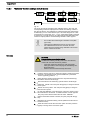
Confirming an entry
Briefly press the [P] key
ð The display simultaneously changes to the next menu option or
into a continuous display.
Quitting a menu point without confirming it
Press and hold the [P] key for 3 seconds
ð Entry is cancelled and you jump back to a continuous display.
B0083
Fig. 20: a) Toggle between changing of individual digits and changing a
number; b) Changes the position within the number; c) jump back in the
number. More detailed explanations are given in the following text.
Incremental changing of a value
Press the [ i ] key once.
You can toggle between altering the digits of a value (“change individual
digits” = standard) and incremental changing of a value (“change a
number”).
35
Adjustment
Changing adjustable values
Press the arrow keys [UP] or [DOWN].
ð The flashing digit or number counts up or down.
Confirming adjustable values
Under "change individual digits": confirm each digit by pressing the
[P] key.
ð Upon confirming the last individual digit, the display simultane‐
ously changes to the next menu option or into a continuous dis‐
play.
Under "change a number": Press the [P] key 1x.
ð The display simultaneously changes to the next menu option or
into a continuous display.
Correcting incorrectly set digits
Press the [ i ] key 2x.
ð You jump back to the first digit.
10.2
Checking adjustable values
Before you adjust the pump control, you can check the actual settings of
the adjustable values:
Press the [ i ] key ("i" for "Info"), if the LCD screen shows a contin‐
uous display (The display does not contain the [P] key symbol).
ð Each press of the [ i ] key toggles the continuous display output
to the screen to another continuous display.
The number of continuous displays depends on the identity code, the
selected operating mode and the connected additional devices, see over‐
view "Continuous displays" in the appendix.
10.3
Changing to adjustment mode
1.
In a continuous display press the [P] key for at least 2 seconds.
ð The pump control changes to adjustment mode.
2.
If ‘CODE 1’ was set, then after pressing the [P] key, the code must
first be entered.
The following menus can initially be chosen in adjustment mode - see also
"Operating/setting overview" in the appendix:
n
n
n
n
36
‘MODE’ menu
‘CODE’ menu (option)
‘SET’ menu
‘CLEAR’ window
Adjustment
To match the pump to your process requirements, you must
observe the following procedure:
1.
In the ‘MODE’ menu select the operating mode.
2.
If necessary make the settings for this operating mode in the ‘SET’
menu.
1.
MODE
menu
CODE
menu
Continuous
display
2s
P
2.
SET
menu
CLEAR
window
B0084
Fig. 21
Exceptions: Timer and PROFIBUS®.
Note the diagram.
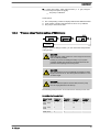
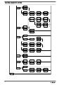
10.4
Operating mode selection (MODE menu)
In the ‘MODE’ menu (dependent on the identity code, some operating
modes may not be present):
n
n
n
n
‘Manual’ : for manual operation (identity code control variant:
"Manual", available as standard)
‘Analog’ : for current control (identity code control variant: "Analog cur‐
rent")
‘Contact’ : for contact operation (identity code control variant:
"External 1:1" / "External with pulse control")
‘Batch’ : for batch operation (identity code control variant: "External
with pulse control")
37
Adjustment
Analog
- ANALOG
Manual
Analog Manual CONTACTBatch
- MANUAL
P
P
CONTACT
- CONTACT
Batch
Continuous
display
- BATCH
B0085
Fig. 22
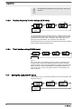
10.5
Operating mode settings (SET menu)
First in the ‘MODE’ menu select the operating mode!
Exceptions: Timer and PROFIBUS®.
In the ‘SET’ menu, you can make various settings dependent on the
selected operating mode.
Setting menus are available in all operating modes for the following pro‐
grammable functions:
n
n
n
Calibrate ( ‘CALIB’ menu)
Auxiliary rate ( ‘AUX’ menu)
Flow ( ‘FLOW’ menu; only available if a dosing monitor is connected) see also the chapter "Programmable function settings (SET menu)".
As to whether or not a further setting menu is available, depends on the
selected operating mode.
10.5.1
"Manual" operating mode settings
Other than those described in more detail in the chapter "Programmable
function settings (SET menu)" there are no other setting menus available
in ‘Manual’ operating mode via the ‘SET’ menu.
10.5.2
Overview
"Analog" operating mode settings (ANALG menu)
Alongside those described in more detail in the chapter "Programmable
function settings (SET menu)" the ‘ANALG’ menu is also available in
‘Analog’ operating mode via the ‘SET’ menu.
The stroke rate is controlled using an analog current signal via the
"External control" terminal
38
Adjustment
Continuous
display
B0086
Fig. 23
You can select three types of current signal processing:
n
‘0 - 20 mA’ :
At 0 mA the pump is stationary.
At 20 mA the pump works at the maximum stroke rate.
Between these values, the stroke rate is proportional to the cur‐
rent signal.
‘4 - 20 mA’ :
– At 4 mA the pump is stationary.
– At 20 mA the pump works at the maximum stroke rate.
– Between these values, the stroke rate is proportional to the cur‐
rent signal.
– For current signals less than 3.8 mA a fault message appears and
the pump stops (e.g. if a cable has broken).
‘Curve’ : Under the ‘Curve’ processing type, you can freely program
the pump behaviour. There are three options:
– Line
– Lower sideband
– Upper sideband
–
–
–
n
n
Continuous
display
B0087
Fig. 24
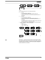
Line
The symbol
appears on the LCD screen. You can enter any stroke
rate- behaviour of the pump proportional to the current signal. For this pur‐
pose, enter any two points P1 (I1, F1) and P2 (I2, F2) (F1 is the stroke rate
at which the pump is to operate at current I1); this defines a straight line
and thus the behaviour is specified:
39
Adjustment
Fmax
P2
F2
P1
F1
0
I2
I1
20
I [mA]
B0088
Fig. 25
F1 Stroke rate at which the pump should operate with current I1
F2 Stroke rate at which the pump should operate with current I2
Plot a diagram similar to the one above - with values for (I1,
F1) and (I2, F2) – so that you can set the pump control as
required.
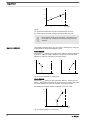
Upper/lower sideband
Using these processing types, you can control a metering pump using the
current signal as shown in the diagrams below.
Lower sideband:
appears on the LCD screen. Below I1, the pump works at
The symbol
a rate of F1 - above I2 it stops. Between I1 and I2 the stroke rate varies
between F1 and F2 in proportion to the signal current.
a)
b)
Fmax
Fmax
P1
F1
P2
F2
P2
F2
P1
F1
0
I1
I2
20
I [mA]
I1
0
I2
20
I [mA]
B0089
Fig. 26: Lower sideband, e.g. alkali pump
Upper sideband:
appears on the LCD screen. Below I1, the pump is sta‐
The symbol
tionary - above I2 the pump works at rate F2. Between I1 and I2 the stroke
rate varies between F1 and F2 in proportion to the signal current.
The smallest processable difference between I1 and I2 is 4 mA
Fmax
P2
F2
P1
F1
0
I1
I2
20
I [mA]
B0090
Fig. 27: Upper sideband, e.g. acid pump
40
Adjustment
Fault processing
10.5.3
Under menu option ‘ER’ (Error) you can activate error processing for the
‘Curve’ processing type. For current signals below 3.8 mA, a fault mes‐
sage appears and the pump stops.
"Contact" operating mode settings (CNTCT menu)
Alongside those described in more detail in the chapter "Programmable
function settings (SET menu)" the ‘CNTCT’ menu is also available in
‘Contact’ operating mode via the ‘SET’ menu.
‘Contact’ operating mode allows you to trigger individual strokes or a
stroke series. You can trigger the strokes via a pulse sent via the "external
control" terminal. The purpose of this operating mode is to convert the
incoming pulses with a reduction (bridge) or small step-up into strokes.
CAUTION!
If you change into another operating mode, the factor is reset
to "1".
With identity code version "Contact - identity code: External with pulse
control", you can enter after how many pulses a stroke should occur.
"Contact - identity code: External with pulse control" is intended for small
metering quantities.
Continuous
display
B0091
Fig. 28
The number of strokes per pulse depends on the factor which you input.
By use of the factor you can multiply incoming pulses by a factor between
1.01 and 99.99 or reduce them by a factor of 0.01 to 0.99:
Number of strokes executed = factor x number of incoming pulses
41
Adjustment
Example
Example table
Step-up
Reduction
Factor
Pulse
(sequence)
Number of
strokes
(sequence)
1
1
1
2
1
2
25
1
25
99.99
1
99.99
1.50
1
1.50 (1 / 2)
1.25
1
1.25 (1 / 1 / 1 /
2)
1
1
1
0.50
2
1
0.50
10
1
0.50
100
1
0.50
4
1
0.50
2.5 (3 / 2)
(1 / 1)
0.50
1.33 (2 / 1 / 1)
(1 / 1 / 1)
Explanation of step-up
Factor
Pulse and strokes
with a factor 1 ...
1 stroke is executed per pulse
with a factor 2 ...
2 strokes are executed per pulse
with a factor 25 ...
25 strokes are executed per pulse
Explanation of reduction
Factor
Pulse and strokes
with a factor 1 ...
1 stroke is completed after 1
pulse
with a factor 0.5 ...
1 stroke is completed after 2
pulses
with a factor 0.1 ...
1 stroke is completed after 10
pulses
with a factor 0.75 ...
1 stroke is completed after 2
pulses once, then 1 stroke is
completed after 1 pulse twice and
then (repeating) 1 stroke after 2
pulses, etc...
If a remainder is obtained when dividing by the factor, then
the pump software adds the remainders together. As soon as
this sum reaches or exceeds "1", the pump executes an
additional stroke. Therefore on average during the metering
operation, the resultant number of strokes precisely matches
the factor.
42
Adjustment
"Memory" function extension
You can also activate the "Memory" function extension (identifier ‘Mem’
appears on the LCD screen; ‘Mem’ = memory). When "Memory" is acti‐
vated, the pump software adds up the remaining strokes , which could not
be processed, up to the maximum capacity of the stroke memory of
65,535 strokes. If this maximum capacity is exceeded, the pump goes into
fault mode.
You can thus optimally match the pump to the process in question, for
example in conjunction with contact water meters.
10.5.4
"Batch" operating mode settings (BATCH menu)
Alongside those described in more detail in the chapter "Programmable
function settings (SET menu)" the ‘BATCH’ menu is also available in
‘Batch’ operating mode via the ‘SET’ menu.
Continuous
display
B0092
Fig. 29
The operating mode ‘Batch’ is a variant of the operating mode ‘Contact’ in the first place see " ‘Contact’ operating mode settings". Here also, you
can select a number of strokes (no fractions, only integers from 1 to
65535), but also a metering quantity (Batch). To change between the input
"Number of strokes" and "Metering quantity" press the [ i ] key 1x under
the corresponding menu option (see "Operating / adjustment overview" in
the appendix).
‘Batch’ operating mode is intended for large metering quantities.
The metering can be triggered either by pressing the [P] key or by a pulse
received via the "External control" terminal.
The number of received pulses, which could not yet be processed, is
stored by the pump control in the stroke memory. The stroke memory is
limited to the Batch size if "Memory" is not activated, with "Memory" to
65535 strokes.
You can delete it by changing to another operating mode.
"Memory" function extension
You can also activate the "Memory" function extension (identifier ‘Mem’
appears on the LCD screen; ‘Mem’ = memory). When "Memory" is acti‐
vated, the pump software adds up the remaining strokes , which could not
be processed, up to the maximum capacity of the stroke memory of
65,535 strokes. If this maximum capacity is exceeded, the pump goes into
fault mode.
You can thus optimally match the pump to the process in question, for
example in conjunction with contact water meters.
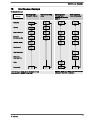
10.6
Programmable function settings (SET menu )
Setting menus are available in the SET menu in all operating modes for
the following programmable functions:
n
n
n
Calibrate ( ‘CALIB’ menu)
Auxiliary rate ( ‘AUX’ menu)
Flow ( ‘FLOW’ menu; (only available if a dosing monitor is connected)
43
Adjustment
10.6.1
“Calibrate” function settings (CALIB menu)
Continuous
display
B0093
Fig. 30
The pump can also be operated in the calibrated state. In this case, the
corresponding continuous displays then indicate the metering volume or
the capacity directly. The calibration is maintained when the stroke length
is altered by up to ±10 scale divisions (for a set stroke length of 40 % this
corresponds to a range from 30 % ... 50 %). If the stroke length is changed
by more than ±10 scale divisions, the yellow warning light illuminates, the
continuous display flashes and the flashing identifier ‘Calib’ appears.
–
–
Do not allow the stroke length to fall below 30% (SEK
type: 50%)!
Otherwise the calibration becomes very inaccurate.
The calibration becomes more accurate, the more
strokes the pump makes during calibration. Recommen‐
dation: at least 200 strokes.
Calibration
CAUTION!
Danger with dangerous feed chemicals
Provided the following handling instructions are followed,
contact with the feed chemical is possible.
–
–
44
If the feed chemical is dangerous, take appropriate
safety precautions when carrying out the following han‐
dling instructions.
Observe the feed chemical safety data sheet.
1.
Lead the suction hose into a measuring cylinder containing the feed
chemical - the discharge hose must be installed in a permanent
manner (operating pressure, ...!).
2.
Prime the feed chemical (press both arrow keys simultaneously),
should the suction hose be empty.
3.
Record the level in the measuring cylinder and the stroke length.
4.
Select the ‘CALIB’ menu and press the [P] key to change to the first
menu option.
5.
With an arrow key select ‘ON’ and press the [P] key to change to
the next menu option.
6.
To start the calibration, press the [P] key. The pump starts to pump
and indicates the stroke rate - at certain intervals ‘STOP’ appears.
The pump works with the stroke rate set under ‘MANUAL’ .
7.
After a reasonable number of strokes, stop the pump with the [P]
key.
8.
Determine the required metering volume (difference initial volume residual volume).
9.
Enter this amount under the next menu option and then press the
[P] key to change to the next menu option.
Adjustment
10.
Under menu option ‘UNIT’ select the units ( ‘L’ or ‘gal’ ) using the
arrow keys and press the [P] key.
ð The pump is calibrated.
Consequence:
n
n
n
10.6.2
The corresponding continuous displays indicate the calibrated values.
Total number of strokes and total litres are set to "0" by calibrate.
The pump is in the STOP state.
“Pressure ratings” function settings (PRESS menu)
Daueranzeige
B0098
Using the "Pressure ratings" function, you can reduce the rated pressure
of the gamma/ L.
CAUTION!
Select the pump rated pressure so it is as large as necessary
and as small as possible!
In doing so you are increasing the safety of your system
(reduced risk that lines will burst if blocked)! Moreover this
preserves the diaphragm and saves power.
CAUTION!
The rated pressure can be considerably exceeded for stroke
lengths less than 100 %. The rated pressure relates to a 100
% stroke length.
CAUTION!
Should a different liquid end size be fitted, then the pump
must be reprogrammed in the factory!
The following rated pressures can be selected for these liquid end sizes:
Selectable rated pressure (bar)
Size of liquid
end
Pressure
rating 1
Pressure
rating 2
Pressure
rating 3
Pressure
rating 4
1601, 1602,
1605
4
7
10
16
1000, 1005,
1008
4
7
10
-
0708, 0713
4
7
-
-
45
Adjustment
No adjustment is possible for pump types 0413, 0420, 0220,
and 0232.
10.6.3
“Auxiliary frequency” function settings (AUX menu)
Continuous
display
B0094
Fig. 31
The programmable function "Auxiliary frequency" facilitates the activating
of an auxiliary stroke rate, which can be set in the ‘AUX’ menu. It can be
activated via the "External control" terminal. If the auxiliary frequency is
being used, then the identifier ‘Aux’ appears in the LCD screen.
This auxiliary frequency has priority over the stroke rate, which is specified
by the currently selected operating mode.
10.6.4
“Flow” function settings (FLOW menu)
Continuous
display
B0095
Fig. 32
The ‘FLOW’ menu only appears if a dosing monitor is connected to the
"Dosing monitor" terminal. The metering monitor records the individual
metering strokes of the pump at the discharge connector and reports them
back to the pump control. If this feedback is sequentially missing for as
often as set in the ‘FLOW’ menu (after a fault or too low metering), the
pump is stopped.
10.7
Setting the code (CODE menu)
In the ‘CODE’ menu, you can enter whether you want to block parts of the
adjustment options.
Continuous
display
Fig. 33
46
B0096
Adjustment
In the first menu option, you can set either CODE 1 or CODE 2 (both use
the same number).
n
n
n
10.8
Select ‘CODE 1’ , to block adjustment mode (① in "Operating / adjust‐
ment overview" in the appendix). In the next menu option, enter the
number you want to use as the code.
Select ‘CODE 2’ , to block the option to adjust the directly changeable
values in the continuous displays (① in "Operating / adjustment over‐
view" in the appendix). In the next menu option, enter the number you
want to use as the code.
Select ‘NONE’ , to clear a set security lock.
Deleting the total number of strokes or total litres (CLEAR window)
Continuous
display
B0097
Fig. 34
In the ‘CLEAR’ window, you can delete the stored total number of strokes
and simultaneously the total litres (= reset to "0"). To do this quit the
Window by quickly pressing the [P] key.
The values have been counted since pump commissioning or since they
were last deleted.
47
Operation
11
Operation
This chapter describes all the operating options available to you if the
pump control is showing a continuous display - then the display does not
contain the symbol for the [P] key.
–
–
11.1
For supplementary information, please read the over‐
views "Control elements and key functions" and see the
"Operating/setting diagram" at the end of the operating
instructions.
Also take note of the overview "Continuous displays". It
shows which continuous displays are available in which
operating mode and which variables are directly change‐
able in the relevant continuous display.
Manual operation
Adjusting the stroke length
The stroke length can be continuously adjusted using the stroke length
adjustment knob in the range 0 ... 100 %. The recommended stroke length
range, in which the set metering quantity can, from a technical point of
view, be accurately reproduced, is 30 ... 100 %
(or for the SEK type: 50 ... 100 %)
The following operating options are available via the keys - see the figure
on the next page:
Stopping/starting the pump
Stop the pump: Press the [START/STOP] key.
Start the pump: Press the [START/STOP] key again.
Starting batch
In operating mode ‘Batch’ : Briefly press the [P] key.
Loading factory settings
Press the [P] key for 15 s, if you want to reload the factory
settings prior to calibration!
This deletes the current settings.
Changing to adjustment mode
In continuous display if you keep the [P] key pressed for 2 s, the pump
control switches into adjustment mode - see "Adjustment" chapter.
If ‘CODE 1’ was set, then after pressing the [P] key, the code must first be
entered.
Checking adjustable values
Each press of the [i] key toggles the continuous display output to the
screen to another continuous display. The number of continuous displays
depends on the identity code, the selected operating mode and the con‐
nected additional devices.
Changing directly changeable variables
To change a value, see below, directly in the corresponding continuous
display, press one of the [arrow keys] until the [Set] identifier appears.
(The delay period has been programmed in to prevent unintentional
changing of values.)
If ‘CODE 2’ was set, then after pressing an [arrow key], the code must
first be entered.
48
Operation
The directly changeable variables are in detail:
Stroke rate
In operating modes ‘Manual’ , ‘Contact’ and ‘Batch’ :
You can change the stroke rate in the ‘Stroke rate’ continuous display.
Capacity
In operating mode ‘Manual’ :
You can change the capacity in the "Capacity" continuous display.
Factor
The factor is the number of strokes which are triggered upon an external
pulse or pressing of key [P] (only in ‘Batch’ operating mode).
In operating mode ‘Batch’ :
You can change the factor from the "Remaining strokes" continuous dis‐
play. A couple of seconds after your have set the factor, the pump control
jumps back to the initial continuous display.
Displaying the program versions
Press the [P] key for 10 s to display the program versions.
‘V1052’ + ‘X1010’
Under ‘LOAD3’ release the [P] key immediately!
Batch size
In operating mode ‘Batch’ :
You can change the batch size from the "Batch size/Remaining litres" con‐
tinuous display. A couple of seconds after your have set the factor, the
pump control jumps back to the initial continuous display.
Priming
Simultaneous pressing of the two [arrow keys] triggers the "Priming" func‐
tion.
Fault acknowledgement
Fault displays are acknowledged by brief pressing of the [P] key.
49
Operation
Continuous
display
STOP
Stop/start pump
START
2
Change directly changeable variables
Prime
P
P
i
P
Start batch (only in "Batch" operating mode)
Acknowledge errors
Check adjustable values
2s
1
1 = Lock (CODE 1)
2 = Lock (CODE 2)
Adjustment
Mode
11.2
B0098
Remote operation
There is an option to control the pump remotely via a signal cable, PRO‐
FIBUS® or CAN bus - see chapter "Settings - selecting the operating mode
(MODE menu)" and chapter "Operation", in the "Supplementary instruc‐
tions for ProMinent® gamma/ L and ProMinent® Sigma versions with PRO‐
FIBUS®" as well as your system documentation.
50
Maintenance
12
Maintenance
WARNING!
It is mandatory that you read the safety information and
specifications in the "Storage, Transport and Unpacking"
chapter prior to shipping the pump.
CAUTION!
Warning of feed chemical spraying around
Feed chemical can spray out of the hydraulic components if
they are manipulated or opened due to pressure in the liquid
end and adjacent parts of the system.
–
–
Disconnect the pump from the mains power supply and
ensure that it cannot be switched on again by unauthor‐
ised persons.
Depressurise the system before commencing any work
on hydraulic parts.
Further data on CD
All product-specific operating instructions include a CD with
order details, exploded diagrams and dimensions sheets, if
they are not included in the operating instructions.
Standard liquid ends:
Interval
Maintenance work
Quarterly*
n
n
n
n
n
n
n
n
Personnel
Check the metering diaphragm for damage** - refer to "Repair".
Check that the hydraulic lines are fixed firmly to the liquid end.
Check that the suction valve and discharge valve are correctly seated.
Check the tightness of the entire liquid end - particularly around the
leakage hole - please refer to Fig. 35!
Check that the flow is correct: Allow the pump to prime briefly - turn the
multifunctional switch briefly to "Test"
Check that the electrical connections are intact
Check the integrity of the housing.
Check that the dosing head screws are tight
Technical personnel
* Under normal loading (approx. 30 % of continuous operation)
Under heavy loading (e.g. continuous operation): Shorter intervals.
** For feed chemicals which particularly load the diaphragm, e.g. those
containing abrasive additives, check the diaphragm frequently.
51
Maintenance
P_BE_0012_SW
Fig. 35: Leakage hole
Liquid ends with bleed valve:
Interval
Maintenance work
Personnel
Quarterly*
In addition:
Technical personnel
n
n
n
n
Check that the bypass line is fixed firmly to the liquid end
Check that the bleed valve is tight.
Check the discharge and bypass line for kinks
Check that the bleed valve is operating correctly.
* Under normal loading (approx. 30 % of continuous operation)
Under heavy loading (e.g. continuous operation): Shorter intervals.
Tightening torque
Data
Tightening torque for screws:
52
Value Unit
4.5 ... 5.0 Nm
Repairs
13
Repairs
Safety notes
WARNING!
Danger of an electric shock
Unauthorised repairs inside the pump can result in an elec‐
tric shock.
For this reason, repairs inside the pump may only be per‐
formed by a ProMinent branch or representative, in particular
the following:
–
–
–
Replacement of damaged mains connection lines
Replacement of fuses
Replacement of electronic control
WARNING!
It is mandatory that you read the safety information and
specifications in the "Storage, Transport and Unpacking"
chapter prior to shipping the pump.
WARNING!
Contact with the feed chemical
Parts that come into contact with the feed chemical are
uncovered and handled during overhaul work.
–
Protect yourself against the feed chemical in case it is
hazardous. Read the safety data sheet on the feed
chemical.
CAUTION!
Warning of feed chemical spraying around
Feed chemical can spray out of the hydraulic components if
they are manipulated or opened due to pressure in the liquid
end and adjacent parts of the system.
–
–
13.1
Disconnect the pump from the mains power supply and
ensure that it cannot be switched on again by unauthor‐
ised persons.
Depressurise the system before commencing any work
on hydraulic parts.
Cleaning valves
Personnel:
n
Technical personnel
Warning of faulty operation
The exploded views on the CD should be referred to when
working on the unit.
53
Repairs
Cleaning a discharge valve or a suction
valve on types (PP, PV, NP) 1000, 1005,
1605, 1601, 1602
Warning of faulty operation
– Discharge and suction valves differ from each other!
Only take them apart one after each other, so that you
do not confuse the components!
– Only use new components which fit your valve - both in
terms of shape and chemical resistance!
– Recalibrate the pump after replacing a valve!
– Using an Allen key or similar, insert it into the smaller
hole of the discharge connector and push the valve
inserts out of it.
A suction valve is constructed in almost the same way as a discharge
valve.
Please note, however, that:
n
n
n
n
Cleaning a discharge valve or a suction
valve on types (PP, PV, NP) 0708, 1008,
0220, 0420, 0413, 0713, 0232
the two valve inserts are identical here
There is an additional spacer between the valve inserts.
There is a shaped seal in the dosing head instead of an O-ring.
The flow direction of the suction connector is the opposite of that of
the discharge connector.
Warning of faulty operation
– Discharge and suction valves differ from each other!
Only take them apart one after each other, so that you
do not confuse the components!
– Only use new components which fit your valve - both in
terms of shape and chemical resistance!
– Readjust the pump after replacing a valve!
– Using an Allen key or similar, insert it into the smaller
hole of the discharge connector and push the valve
inserts out of it.
A suction valve is constructed in almost the same way as a discharge
valve.
Please note, however, that:
n
n
n
54
The shaped seal is laid in the suction connector.
Only the O-ring, not the shaped seal, is laid in the dosing head.
The flow direction of the suction connector is the opposite of that of
the discharge connector.
Repairs
13.2
Replacing the metering diaphragm
WARNING!
A few cubic centimetres of feed chemical may have accumu‐
lated behind the metering diaphragm in the backplate fol‐
lowing a leak - depending on the design!
–
Personnel:
n
n
n
Take this feed chemical into consideration when you are
planning a repair - especially if it is hazardous!
n
Technical personnel
If necessary take protective measures.
Observe the safety data sheet for the feed chemical.
Depressurise the system.
1.
Empty the liquid end (turn the liquid end upside down and allow the
feed chemical to run out; flush out with a suitable medium; flush the
liquid end thoroughly when using hazardous feed chemicals!)
2.
Turn the stroke adjustment dial until the stop at 0 % stroke length if
the pump is running (the drive axle is then difficult to turn).
3.
Switch off the pump.
4.
Unscrew the hydraulic connectors on the discharge and suction
side.
5.
With types with bleed valve: Firstly remove the bleed valve (star
handle), then lift off the cover of the liquid end with a screwdriver.
6.
Remove the screws (1).
For pump types 0220, 0232 and 0420 - refer to the following page (there
are 4 holes on the diaphragm edge).
Liquid end types with the exception of
0220 , 0232 and 0420
1.
Loosen the dosing head (2) and the backplate (4) from the pump
housing (6) - but only loosen!
2.
Hold the pump housing (6) with one hand and clamp the diaphragm
(3) with the other hand between the dosing head (2) and the back‐
plate (4).
3.
Loosen the diaphragm (3) from the drive axle with a gentle back‐
wards turn of the dosing head (2), diaphragm (3) and backplate (4)
in an anticlockwise direction.
4.
Unscrew the diaphragm (3) completely from the drive axle.
5.
Remove the backplate (4) from the pump housing (6).
6.
Check the condition of the safety diaphragm (5) and replace if nec‐
essary.
7.
Push the safety diaphragm (5) onto the drive axle only until it lies
flush with the pump housing (6) and no further!
8.
Tentatively screw the new diaphragm (3) onto the drive axle until its
stop position.
ð The diaphragm (3) is now sitting at the stop of the thread.
9.
Should this not work, remove dirt or swarf out of the threads and
screw the diaphragm (3) onto the drive axle correctly this time.
The diaphragm must be screwed exactly onto the
drive axle otherwise the pump will subsequently not
meter correctly!
55
Repairs
10.
Unscrew the diaphragm (3) again.
11.
Place the backplate (4) onto the pump housing (6).
CAUTION!
Leakage may become apparent at a later stage.
– The leakage hole must point downwards when the
pump is installed later - please refer to
Ä on page 57!
– Place the backplate (4) immediately into the cor‐
rect position on the pump housing (6)! Do not twist
the backplate on the pump housing so that the
safety diaphragm (5) becomes warped!
12.
Place the diaphragm (3) into the backplate (4).
CAUTION!
Leakage may become apparent at a later stage.
– Do not over-tighten the diaphragm (3) in the fol‐
lowing step!
– The backplate (4) must remain in its position so
that the safety diaphragm does not become
warped!
13.
Hold the backplate (4) firmly and screw the diaphragm (3) in a clock‐
wise direction until it is sitting tightly (the twisting resistance of the
return spring can be felt).
14.
Set the stroke length to 100 %.
15.
Place the dosing head (2) with the screws (1) onto the diaphragm
(3) and the backplate (4) - the suction connector must be pointing
downwards in the pumps subsequent fitting position.
16.
Gently tighten the screws (1) and then tighten in a diagonal pattern.
See below for tightening torque.
17.
With types with bleed valve: Allow the cover of the liquid end to rest
in the dosing head, then press the knob on the bleed valve (star
handle) into the dosing head.
CAUTION!
Leakage possible
– Check the tightening torque of the screws after
24-hours of operation!
– With PP and PVDF dosing heads, recheck the
tightening torque again after three months!
Tightening torque
Data
Tightening torque for screws:
56
Value Unit
4.5 ... 5.0 Nm
Repairs
1
2
3
4
5
6
P_G_0008_SW
Fig. 36: Partially exploded view of liquid end
Liquid end types 0220 , 0232 and 0420
1.
Remove the dosing head (2) with the screws (1) from the pump.
Only type 0232: Remove the screws of the backplate (4) under the
diaphragm (3). Replace the dosing head (2) and screws - the
screws (1) should still extend into the holes in the diaphragm (3),
but not into the backplate!
2.
Hold the pump housing (6) with one hand and clamp the diaphragm
(3) with the other hand between the dosing head (2) and the back‐
plate (4).
3.
Loosen the diaphragm (3) from the drive axle with a gentle back‐
wards turn of the dosing head (2), diaphragm (3) and backplate (4)
in an anticlockwise direction.
4.
Pull the dosing head (2) with the screws (1) out of the diaphragm (3)
and completely unscrew this from the drive axle.
5.
Remove the backplate (4) from the pump housing (6).
6.
Check the condition of the safety diaphragm (5) and replace if nec‐
essary.
7.
Push the safety diaphragm (5) onto the drive axle only until it lies
flush with the pump housing (6) and no further!
8.
Tentatively screw the new diaphragm (3) onto the drive axle until its
stop position.
ð The diaphragm (3) is now sitting at the stop of the thread.
9.
Should this not work, remove dirt or swarf out of the threads and
screw the diaphragm (3) onto the drive axle correctly this time.
The diaphragm must be screwed exactly onto the
drive axle otherwise the pump will subsequently not
meter correctly!
10.
Unscrew the diaphragm (3) again.
11.
Check whether the diaphragm holes align correctly with the pump
housing.
12.
If not, start the pump and adjust the stroke length to 100 %.
13.
With the pump running, slowly turn the diaphragm (3) in the clock‐
wise direction until the 4 diaphragm holes align correctly with the
pump housing (6).
14.
Clamp the diaphragm (3) in this position, adjust the stroke length to
0 % and stop the pump.
15.
Unscrew the diaphragm (3) again.
57
Repairs
16.
Place the backplate (4) onto the pump housing (6).
CAUTION!
Leakage may become apparent at a later stage.
– The leakage hole must point downwards when the
pump is installed later - please refer to Ä ‘Liquid
end types 0220 , 0232 and 0420’ on page 57!
– Place the backplate (4) immediately into the cor‐
rect position on the pump housing (6)! Do not twist
the backplate on the pump housing so that the
safety diaphragm (5) becomes warped!
17.
Only type 0232: Screw the backplate (4) on tightly using the screws.
18.
Place the diaphragm (3) into the backplate (4).
CAUTION!
Leakage may become apparent at a later stage.
– Do not over-tighten the diaphragm (3) in the fol‐
lowing step!
– The backplate (4) must remain in its position so
that the safety diaphragm does not become
warped!
19.
Hold the backplate (4) firmly and screw the diaphragm (3) in a clock‐
wise direction until it is sitting tightly (the twisting resistance of the
return spring can be felt).
20.
Place the dosing head (2) with the screws (1) onto the diaphragm
(3) and the backplate (4) - the suction connector must be pointing
downwards in the pumps subsequent fitting position.
21.
Gently tighten the screws (1) and then tighten in a diagonal pattern.
Tightening torque - see above.
22.
With types with bleed valve: Allow the cover of the liquid end to rest
in the dosing head, then press the bleed valve (star handle) into the
dosing head.
CAUTION!
Leakage possible
– Check the tightening torque of the screws after
24-hours of operation!
– With PP and PVDF dosing heads, recheck the
tightening torque again after three months!
1
2
3
4
5
6
P_G_0009_SW
Fig. 37: Partially exploded view of liquid end
58
Troubleshooting
14
Troubleshooting
Safety notes
WARNING!
Warning of hazardous or unknown feed chemical
Should a hazardous or unknown feed chemical be used, it
may escape from the hydraulic components when working
on the pump.
–
–
Take appropriate protective measures before working on
the pump (protective eyewear, protective gloves, ...).
Read the safety data sheet on the feed chemical.
Drain and flush the liquid end before working on the
pump.
CAUTION!
Warning of feed chemical spraying around
Feed chemical can spray out of the hydraulic components if
they are manipulated or opened due to pressure in the liquid
end and adjacent parts of the system.
–
–
14.1
Disconnect the pump from the mains power supply and
ensure that it cannot be switched on again by unauthor‐
ised persons.
Depressurise the system before commencing any work
on hydraulic parts.
Faults without a fault alert
Faults without a fault alert
Fault description
Cause
Remedy
Personnel
Take suction hose out of the
storage tank and thoroughly flush
out the liquid end
Technical per‐
sonnel
Major crystalline deposits on
the ball seat due to the valves
drying out
Dismantle the valves and clean
them - refer to "Repair"
Technical per‐
sonnel
The screws in the dosing head
are too loose
Tighten the screws in the dosing
head crosswise - refer to "Repair"
for tightening torque.
Instructed per‐
sonnel
The metering diaphragm is not
tight
Replace the metering diaphragm refer to "Repair".
Technical per‐
sonnel
Pump does not prime in spite Minor crystalline deposits on
the ball seat due to the valves
of full stroke motion and
drying out
bleeding
Fluid is escaping from the
backplate
Green LED display (oper‐
ating display) does not light
up
14.2
14.2.1
The wrong mains voltage or no The specified mains voltage can
mains voltage is connected.
be found on the nameplate.
Electrician
Faults with error message
Fault alerts
Fault description
Cause
The red LED indicator illuminates, on the dis‐ The fluid level in the storage tank
play, the identifiers ‘Error’ and ‘MINIM’ flash. has reached "liquid level low 2nd
stage".
Remedy
Fill storage tank.
59
Troubleshooting
Fault description
Cause
Remedy
The red LED indicator illuminates, on the dis‐
play, the identifiers ‘Error’ and ‘ANALG’
flash.
The pump control is in ‘Analog’
operating mode, a fault behaviour
has been programmed in the
‘ANALG’ menu and the control
current has fallen below 3.8 mA.
Clear the cause of the low control
current.
The red LED indicator illuminates, on the dis‐
play, the identifiers ‘Error’ and ‘CNTCT’
flash.
Pump control is in the operating
mode ‘Contact’ or ‘Batch’ and
the function extension "Memory"
has been set. Also a very large
factor was set, too many contacts
have been received or the key [P]
has been pressed too often: Con‐
sequently a stroke memory over‐
flow has occurred!
Press the [P] key, the memory
content is deleted.
The red LED indicator illuminates, on the dis‐
play, the identifiers ‘Error’ and ‘FLOW’ flash.
Dosing monitor not correctly con‐
nected.
Connect the dosing monitor cor‐
rectly.
Switch the programming of the
fault behaviour to ‘OFF’ - see
chapter "Adjustment - Operating
mode settings (SET menu)".
Set up the pump again.
Press the [P] key.
The dosing monitor reported more Press the [P] key.
defective strokes than was set in
Investigate and clear the cause.
the ‘FLOW’ menu.
The red LED indicator illuminates, on the dis‐
play, the identifiers ‘Error’ and
‘TEMPERATURE’ flash.
The temperature inside the pump Ensure lower outside tempera‐
housing is too high due to too high tures.
outside temperature.
Allow the pump to cool.
Press the [P] key (reset function).
The temperature inside the pump Check the installation, change if
housing is too high due to too high necessary.
pump power consumption.
Allow the pump to cool.
Press the [P] key (reset function).
The red LED indicator illuminates, on the dis‐
play, the identifiers ‘Error’ and ‘DIAPH’
flash.
Metering diaphragm is ruptured.
Replace metering diaphragm
according to chapter "Repairs".
The red LED indicator illuminates, on the dis‐
play, the identifiers ‘Error’ and ‘FAN’ flash.
Error in connection with fan in
pump housing.
Check the fan, replace if neces‐
sary.
Press the [P] key (reset function).
The red LED indicator illuminates, on the dis‐
play, the identifiers ‘Error’ and ‘SYSTEM’
flash.
Fault on the control.
Disconnect the pump from the
mains/power supply then recon‐
nect.
If the error message continues to
appear, send the pump to ProMi‐
nent.
The red LED indicator illuminates, on the dis‐
play, the identifiers ‘Error’ and ‘MEM’ flash.
14.2.2
Stroke memory overflow has
occurred.
Eliminate cause.
Press [P] key - bear in mind the
consequences for your process.
Warning Alerts
Fault description
Cause
Remedy
Green LED indicator illuminates.
The liquid level in the storage tank has reached "liquid
level low 1st stage".
Fill storage tank.
Green LED indicator illuminates The pump is calibrated and the stroke length varies by Reset the stroke length or
and the identifier ‘Calib’ flashes. more than ±10 scale divisions from the value at the
recalibrate the pump at the
time of the calibration.
desired stroke length.
60
Troubleshooting
14.3
All Other Faults
Please contact the responsible ProMinent branch or representative!
61
Decommissioning
15
Decommissioning
Decommissioning
WARNING!
Danger from chemical residues
There is normally chemical residue in the liquid end and on
the housing after operation. This chemical residue could be
hazardous to people.
–
–
It is mandatory that the safety information relating to the
"Storage, transport and unpacking" chapter is read
before shipping or transporting the unit.
Thoroughly clean the liquid end and the housing of
chemicals and dirt. Adhere to the safety data sheet for
the feed chemical.
WARNING!
Warning of hazardous or unknown feed chemical
Should a hazardous or unknown feed chemical be used, it
may escape from the hydraulic components when working
on the pump.
–
–
Take appropriate protective measures before working on
the pump (protective eyewear, protective gloves, ...).
Read the safety data sheet on the feed chemical.
Drain and flush the liquid end before working on the
pump.
CAUTION!
Warning of feed chemical spraying around
Feed chemical can spray out of the hydraulic components if
they are manipulated or opened due to pressure in the liquid
end and adjacent parts of the system.
–
–
Disconnect the pump from the mains power supply and
ensure that it cannot be switched on again by unauthor‐
ised persons.
Depressurise the system before commencing any work
on hydraulic parts.
Danger of damage to the device
Take into account the information in the "Storage, Transport
and Unpacking" chapter if the system is decommissioned for
a temporary period.
Personnel:
62
n
Technical personnel
1.
Disconnect the pump from the mains power supply.
2.
Empty the liquid end by turning the pump upside down and allowing
the feed chemical to run out.
3.
Flush the liquid end with a suitable medium; flush the dosing head
thoroughly when using hazardous feed chemicals!
Decommissioning
Disposal
CAUTION!
Warning of feed chemical spraying around
Feed chemical can spray out of the hydraulic components if
they are manipulated or opened due to pressure in the liquid
end and adjacent parts of the system.
–
–
Personnel:
Disconnect the pump from the mains power supply and
ensure that it cannot be switched on again by unauthor‐
ised persons.
Depressurise the system before commencing any work
on hydraulic parts.
n
Technical personnel
CAUTION!
Environmental hazard due to electronic waste
There are electronic components in the pump, which can
have a toxic effect on the environment.
–
–
Separate the electronic components from the remaining
parts.
Note the pertinent regulations currently applicable in
your country!
63
Technical data
16
16.1
Technical data
Performance data
gamma/ L operating at 180 strokes/minute
and 100 % stroke length
Type
Minimum pump capacity
Minimum pump capacity
at maximum back pressure
at medium back pressure
Con‐
nector
size
Suction
lift*
Priming
lift**
Max‐
imum
priming
pressure
on suc‐
tion side
outside
Æx
inside Æ
bar
l/h
ml/
stroke
bar
l/h
ml/
stroke
mm
m WS
m WS
bar
1000
10
0.74
0.069
5.0
0.82
0.076
6x4
6.0
1.8
8
1601
16
1.1
0.10
8.0
1.40
0.13
6x4
6.0
2.0
8
1602
16
2.1
0.190
8.0
2.5
0.24
6x4
6.0
2.5
5.5
1005
10
4.4
0.41
5.0
5.0
0.46
8x5****
5.0
3.0
3
0708
7
7.1
0.66
3.5
8.4
0.78
8x5
4.0
2.0
2
0413
4
12.3
1.14
2.0
14.2
1.31
8x5
3.0
2.5
1.5
0220
2
19.0
1.76
1.0
20.9
1.94
12x9
2.0
2.0
1
1605
16
4.1
0.38
8.0
4.9
0.45
8x5****
4.0
3.0
3
1008
10
6.8
0.63
5.0
8.3
0.76
8x5
3.0
3.0
2
0713
7
11.0
1.02
3.5
13.1
1.21
8x5
3.0
3.0
1.5
0420
4
17.1
1.58
2.0
19.1
1.77
12x9
3.0
3.0
1
0232
2
32.0
2.96
1.0
36.2
3.35
12x9
2.0
2.0
0.8
gamma/ L
gamma/ L Metering pumps with self-bleeding dosing head SEK***
1601
16
0.59
0.055
8.0
0.78
0.072
6x4
1.8
1.8
0.5
1602
16
1.40
0.13
8.0
1.74
0.16
6x4
2.1
2.1
0.5
1005
10
3.6
0.33
5.0
4.0
0.37
8x5
2.7
2.7
0.5
0708
7
6.60
0.61
3.5
7.50
0.69
8x5
2.0
2.0
0.5
0413
4
10.8
1.0
2.0
12.6
1.17
8x5
2.5
2.5
0.5
0220
2
16.2
1.5
1.0
18.0
1.67
12x9
2.0
2.0
0.5
1605
16
3.3
0.31
8.0
3.8
0.35
8x5
3.0
3.0
0.5
1008
10
6.3
0.58
5.0
7.5
0.69
8x5
3.0
3.0
0.5
0713
7
10.5
0.97
3.5
12.3
1.14
8x5
2.5
2.5
0.5
0420
4
15.6
1.44
2.0
17.4
1.61
12x9
2.5
2.5
0.5
*
- Suction lift with a filled suction line and filled liquid end. With selfbleeding dosing head with air in the suction line.
**
- Priming lift with clean and moist valves. Priming lift at 100 % stroke
length and free outlet or opened bleed valve.
***
- The given performance data constitutes guaranteed minimum
values, calculated using medium water at room temperature. The
bypass connection with a self-bleeding dosing head is 6x4 mm.
**** - The connector width is 6 mm on SST material versions.
64
Technical data
16.2
16.2.1
Accuracy
Standard Liquid End
Data
Value Unit
Capacity range of the series
-5 ... +10 % *
Reproducibility
*
±2 % **
- at max. stroke length and max. operating pressure for all material
versions
** - at constant conditions and min. 30 % stroke length
16.2.2
Self-Bleeding Liquid End
As the self-bleeding liquid end is used with outgassing media and when
operating with air bubbles, no dosing accuracy or reproducibility can be
provided.
The recommended minimum stroke length with self-bleeding dosing
pumps is 50 %.
16.3
Viscosity
The liquid ends are suitable for the following viscosity ranges:
Version
Range
Unit
Standard
0 ... 200
mPa
With valve springs
200 ... 500
mPa
Self-bleeding (SEK)
0 ... 50
mPa
* Only when the installation is correctly adjusted
65
Technical data
16.4
Material specifications
Standard liquid ends
Version
Dosing head
Suction/dis‐
charge con‐
nector
Seals
Valve balls
PPE
Polypropy‐
lene
Polypropy‐
lene
EPDM
Ceramic
PPB
Polypropy‐
lene
Polypropy‐
lene
FPM
Ceramic
NPE
Clear acrylic
PVC
EPDM
Ceramic
NPB
Clear acrylic
PVC
FPM
Ceramic
PVT
PVDF
PVDF
PTFE
Ceramic
TTT
PTFE with
carbon
PTFE with
carbon
PTFE
Ceramic
SST
Stainless
steel 1.4571
Stainless
steel 1.4571
PTFE
Ceramic
Only the self-bleeding design in material version PPE, PPB, NPE and
NPB: valve spring made of Hastealloy C, valve insert made of PVDF.
Metering diaphragms with a PTFE coating.
FPM = fluorine rubber.
Pump
16.5
Housing parts: polyphenylene ether (PPE with fibreglass)
Electrical data
Version: 100 - 230 V ±10 %, 50/60 Hz,
gamma/ L GALa
Parameter
M70
M85
Nominal power, approx.
17 W
23 W
Current I eff
0.5 ... 0.2 A
0.8 ... 0.3 A
Peak current
3.6... 1.4 A
6.0 ... 2.8 A
Switch on peak current (within approx. 15 A
1 ms)
15 A
Fuse*
0.8 AT
0.8 AT
* Fuses must have VDE, UL and CSA certification. E.G. type 19195 manu‐
factured by Wickmann in compliance with IEC Publ. 127 - 2/3.
16.6
Temperatures
Pump, compl.
66
Data
Value Unit
Storage and transport temperature
-10 ... +50 °C
Ambient temperature in operation (drive
and control):
-10 ... +45 °C
Permissible medium temperature
-10 ... +35 °C
Technical data
Liquid end, short-term*
Material version
Unit
Temporary *
PP
50 °C
100 °C
NP
45 °C
60 °C
PV
45 °C
120 °C
TT
50 °C
120 °C
SS
50 °C
120 °C
* Temp. max., for 15 min at max. 2 bar, dependent on the ambient and
feed chemical temperatures
16.7
Climate
Data
Maximum air humidity *:
Value Unit
95 % rel.
humidity
* non-condensing
Exposure in a humid and alternating climate:
FW 24 according to DIN 50016
16.8
Protection class and Safety Requirements
Degree of protection
Protection against contact and humidity:
IP 65 in accordance with IEC 529, EN 60529, DIN VDE 0470 Part 1
Safety requirements
Degree of protection:
1 - mains power connection with protective earth conductor
16.9
Compatibility
Some hydraulic parts of the gamma/ L are identical to those of the Beta®
product range.
There is substantial compatibility with the following components and
accessories with pumps in the product ranges Beta®, CONCEPT, gamma
and gamma-Classic:
n
n
n
n
n
n
n
n
n
Signal cable gamma/Vario 2-, 4- and 5-wire for the "External" function
Level switch 2-stage (gamma / Vario / Beta®)
Metering line cross-sections
Standard gamma connector kit
gamma wall bracket
Chemical feed containers and fastening plates
Overall height (distance between the suction and discharge con‐
nector)
Distance between the connectors and the pump fixing holes
Identical use of accessories, such as back pressure valves, multifunc‐
tional valves, dosing monitor and flushing equipment
67
Technical data
16.10 Sound pressure level
Sound pressure level
Sound pressure level LpA < 70 dB in accordance with EN ISO
20361:2010-10
at maximum stroke length, maximum stroke rate, maximum back pressure
(water)
16.11 Shipping weight
Shipping weight of gamma/ L types - in kg
Material
Types
1000, 1601, 1602
1005, 0708, 0413,
0220
1605, 1008, 0713
0420, 0232
PP, NP, PV, TT
2.9
3.1
4.5
5.5
SS
3.6
4.5
5.9
8.6
68
EC Declaration of Conformity
17
EC Declaration of Conformity
For mains voltage pumps:
- Original EC Declaration of Conformity for Machinery
We,
ProMinent Dosiertechnik GmbH
Im Schuhmachergewann 5 - 11
DE - 69123 Heidelberg
that the following designated product complies with the pertinent fundamental safety and health requirements of the EC
Directive in terms of its design and
construction and in terms of the version marketed by us.
This declaration loses its validity in the event of a modification to the product not agreed with us.
Description of the product:
Metering pump, Gamma L product range
Product type:
GALa _ _ _ _ _ _ _ _U_ _ _ _ _ _ _
Serial no.:
Please refer to nameplate on the device
Pertinent
EC - Machinery Directive (2006/42/EC)
EC Directives:
EC EMC Directive (2004/108/EC)
The safety objectives of the Low Voltage Directive 2006/95/EC are
complied
with with Appendix I, No. 1.5.1
in accordance
of the Machinery Directive 2006/42/EC
Applied harmonised standards
EN ISO 12100, EN 809,
in particular:
EN 60335-1, EN 60335-2-41, EN 50106,
EN 61000-3-3, EN 61000-4-2/3/4/5/6/11, EN 61000-6-1/2/3/4
Technical documents have been
compiled by:
Norbert Berger
Im Schuhmachergewann 5-11
DE-69123 Heidelberg
Documentation specialist:
Date
/
Manufacturer's
Details of the signatory:
signature:
5.10.2011
Joachim Schall, Head of Development
69
EC Declaration of Conformity
For low voltage pumps:
- Original EC Declaration of Conformity for Machinery
We,
ProMinent Dosiertechnik GmbH Im
Schuhmachergewann 5 - 11
DE - 69123 Heidelberg
hereby declare that, the product specified in the following complies with the relevant basic health and safety rules of the EC
Directive, on the basis of its functional concept and design and in the version marketed by us.
This declaration loses its validity in the event of a modification to the product not agreed with us.
70
Description of the product:
Metering pump, Gamma L product range
Product type:
GALa _ _ _ _ _ _ _ M_ _ _ _ _ _ _ _
GALa_ _ _ _ _ _ _ N _ _ _ _ _ _ _ _
GALa_ _ _ _ _ _ _P _ _ _ _ _ _ _ _
Serial no.:
Please refer to nameplate on the device
Relevant EC
Directives:
EC Machinery Directive (2006/42/EC) EC EMC directive (2004/108/EC)
Harmonised standards applied, in
particular:
EN ISO 12100, EN 809,
EN 60335-1, EN 60335-2-41, EN 50106,
EN 61000-3-3, EN 61000-4-2/3/4/5/6/11,
EN 61000-6-1/2/3/4
Technical documents have been
compiled by documentation specialists:
Norbert Berger
Im Schuhmachergewann 5-11
DE-69123 Heidelberg
Date / manufacturer's signature:
5.10.2011
Details of the signatory:
Joachim Schall, Head of Development
Operating / adjustment overview
18
Operating / adjustment overview
Continuous
display
Stop/start pump
= Lock (CODE 1)
= Lock (CODE 2)
Change directly changeable variables
Prime
Start batch (only in "Batch" operating mode)
Acknowledge errors
Check adjustable values
P_SI_0040_SW
71
Operating / adjustment overview
P_G_0007_SW
72
Continuous displays
19
Continuous displays
Continuous displays
Continuous
display
Operating mode
"Analog" 0...20 mA
"Manual" operating
mode
Operating mode
"Contact" with
memory and transfer
factor 5
"Batch" operating
mode with memory
Stroke rate
Capacity
Total number of strokes
Total litres
(metering quantity)
"External" display
Signal current
Remaining strokes
Batch size /
Remaining litres
Factor
Stroke length
B0100
= values which can be changed directly
using the UP or DOWN arrow keys
B0101
B0102
B0103
Identifier "Mem" only in the event that function
extension "Memory" is activated
73
Index
20
Index
"
Disposal........................................................................ 63
"Analog" operating mode settings................................. 38
Dosing monitor........................................................ 32, 46
"Batch" operating mode settings................................... 43
E
"Contact" operating mode settings................................ 41
Electrical data................................................................ 66
"External control" terminal............................................. 31
Emergency.................................................................... 12
"Manual" operating mode settings................................ 38
Emptying the liquid end................................................. 62
1, 2, 3 ...
Explanation of the safety information ............................. 9
4 - 20 mA....................................................................... 38
External contact................................................ 21, 31, 32
A
External frequency changeover.................................... 21
Accuracy....................................................................... 65
F
Adjustment.................................................................... 35
Factor............................................................................ 41
Adjustment mode.......................................................... 36
Fault.............................................................................. 21
Analog............................................................... 19, 32, 38
Fault indicating relay............................................... 21, 33
Analog output................................................................ 31
Fault indicator.......................................................... 17, 21
Anti-kink device............................................................. 28
Fault processing............................................................ 41
Assembly....................................................................... 22
Fault statuses................................................................ 21
Auxiliary frequency...................................... 20, 31, 32, 46
Flow............................................................................... 20
Auxiliary rate................................................................. 21
FLOW menu.................................................................. 46
AUX menu..................................................................... 46
Function............................................................ 44, 45, 46
B
Function display............................................................ 21
Basic principles of pump adjustment............................. 35
Functions........................................................... 19, 21, 43
Batch....................................................................... 20, 43
H
Bleeding.................................................................. 26, 27
Hierarchy of operating modes....................................... 21
Bleed valve.................................................................... 28
I
BUS............................................................................... 20
Identity code.................................................................... 6
C
Incorrectly set digits...................................................... 36
CALIB menu.................................................................. 44
Incremental changing of a value................................... 35
Calibration............................................................... 20, 44
Inductive consumers..................................................... 30
Changing a number....................................................... 35
Information in the event of an emergency..................... 12
Changing individual numbers........................................ 35
Installation, electrical..................................................... 29
Changing to adjustment mode...................................... 36
Installation, hydraulic..................................................... 23
check............................................................................. 36
Install hose lines............................................................ 24
Checking adjustable values.......................................... 36
IP................................................................................... 67
Cleaning valves............................................................. 53
K
CLEAR window............................................................. 47
Keys.............................................................................. 17
Code setting.................................................................. 46
L
Compatibility.................................................................. 67
LCD screen................................................................... 17
Confirming an entry....................................................... 35
Leakage hole................................................................. 51
Connector size.............................................................. 64
Level switch....................................................... 20, 32, 33
CONTACT............................................................... 19, 41
Line............................................................................... 39
Contacter relay.............................................................. 30
Lock............................................................................... 46
Control elements........................................................... 16
Lower sideband ...................................................... 39, 40
Correct.......................................................................... 36
M
Correct and proper use................................................... 9
Mains Cable.................................................................. 30
Curve............................................................................. 38
Maintenance.................................................................. 51
D
Manual.............................................................. 19, 21, 38
Decommissioning.......................................................... 62
mA output...................................................................... 31
Degree of protection...................................................... 67
Material specifications................................................... 66
delete...................................................................... 43, 47
Memory......................................................................... 43
Deleting the total number of strokes or total litres......... 47
Metering pumps with bleed valve.................................. 26
Discharge valve............................................................. 28
Metering pumps without self-bleeding........................... 24
74
Index
Metering pumps with self-bleeding................................ 27
S
Minimum Stroke Length................................................ 65
Safety chapter................................................................. 9
MODE menu........................................................... 19, 37
Safety declaration form................................................. 14
O
Safety requirements...................................................... 67
Operating indicator.................................................. 17, 21
Scope of supply............................................................. 15
Operating mode................................................ 38, 41, 43
SEK............................................................................... 27
Operating modes..................................................... 19, 21
SEK types..................................................................... 19
Operating mode selection............................................. 37
Self-Bleeding................................................................. 19
Operating mode settings............................................... 38
Semiconductor switch................................................... 33
Options.......................................................................... 19
SET menu............................................................... 38, 43
Output relay................................................................... 21
Shipping weight............................................................. 68
Overview of equipment................................................. 16
Sleeve........................................................................... 28
P
Sockets......................................................................... 17
Pacing relay............................................................ 21, 33
Sound pressure level.............................................. 13, 68
Parallel connection........................................................ 30
Step-up.......................................................................... 42
Pause................................................................ 20, 21, 31
Stop......................................................................... 20, 21
Performance data.......................................................... 64
Storage.......................................................................... 14
Power consumption....................................................... 66
Stroke length adjustment knob...................................... 17
PRESS menu................................................................ 45
Supply Voltage.............................................................. 30
Pressure ratings............................................................ 45
T
Priming.................................................................... 20, 21
Technical data............................................................... 64
Priming pressure........................................................... 27
Total litres...................................................................... 47
Programmable function settings.................................... 43
Transport....................................................................... 14
Protect........................................................................... 46
U
Protection against contact and humidity....................... 67
Unpacking..................................................................... 14
Protection class............................................................. 67
Upper sideband....................................................... 39, 40
Q
V
Qualification of personnel.............................................. 12
Varistor.......................................................................... 30
Quitting a menu point without confirming it................... 35
Viscosity........................................................................ 65
R
W
Radioactive................................................................... 14
Warning alert................................................................. 33
RC member................................................................... 30
Warning indicator.................................................... 17, 21
Reduction...................................................................... 42
Warning sign................................................................... 9
Relay............................................................................. 33
“
Repairs.......................................................................... 53
“Auxiliary rate” function settings.................................... 46
Replacing the Diaphragm.............................................. 55
“Calibrate” function settings.......................................... 44
Replacing the metering diaphragm............................... 55
“Flow” function settings................................................. 46
Reproducibility............................................................... 65
“Pressure ratings” function settings............................... 45
Return line......................................................... 24, 26, 27
75