1
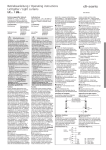
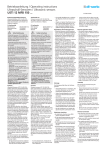
Betriebsanleitung / Operating instructions
Reflexions-Lichtschranken / Retro reflective sensors
ORV...
Bestimmungsgemäßer Gebrauch
Reflexions-Lichtschranken werden als Bestandteil eines übergeordneten Gesamtsystems zur Erfassung von Objekten eingesetzt.
Authorized use
Retro reflective sensors are used as a
part of a higher-level overall system for
detection of objects.
-Konformität
EMV-Richtlinie
conformity
EMV directive
Niederspannungsrichtlinie
Störaussendung
DIN EN 50081-1
Störfestigkeit
DIN EN 61000-6-2
73/23/EWG
93/68/EWG
EN 61010
Sicherheitshinweise
Low voltage
directive
Emitted interference
DIN EN 50081-1
Interference immunity
DIN EN 61000-6-2
73/23/EWG
93/68/EWG
EN 61010
Safety instructions
Reflexions-Lichtschranken sind nicht
zulässig für Sicherheitsanwendungen,
insbesondere bei denen die Sicherheit
von Personen von der Gerätefunktion
abhängig ist.
Retro reflective sensors are not to be
used for safety applications, in particular
applications in which safety of persons
depends on proper operation of the
instruments.
Der Betreiber des übergeordneten
Gesamtsystems, z.B. einer Maschinenanlage, ist für die Einhaltung der für den
speziellen Einsatzfall geltenden
nationalen und internationalen
Sicherheits- und Unfallverhütungsvorschriften verantwortlich.
The operator of the higher-level overall
system, e.g. a machine installation, is
responsible for complying with the
national and international safety and
accident prevention regulations which
apply to the specific use.
Bei Maschinenplanung und Verwendung
der Reflexions-Lichtschranken sind die
einsatzspezifischen Sicherheits- und
Unfallverhütungsvorschriften einzuhalten, wie z.B.:
- EN 60204, Elektrische Ausrüstung von
Maschinen
- EN 292, Sicherheit von Maschinen,
allgemeine Gestaltungsleitsätze
- DIN 57100 Teil 410, Schutz gegen
gefährliche Körperströme
Montage und elektrischer Anschluß der
Reflexions-Lichtschranken darf nur von
Fachpersonal nach geltenden
Vorschriften in spannungsfreiem
Zustand und bei ausgeschalteter
Maschine erfolgen.
Die Maschine muß gegen Wiedereinschalten gesichert sein.
Funktion
Bei Reflexions-Lichtschranken befinden
sich Sender und Empfänger im gleichen
Gehäuse. Das Sendelicht wird von einem
Reflektor auf den Empfänger reflektiert.
Unterbricht ein Objekt den Lichtstrahl,
erfolgt eine Änderung des Ausgangszustands.
Die Reflexions-Lichtschranken arbeiten mit
rotem Sendelicht.
Der dadurch im Reflektor sichtbare
Lichtfleck vereinfacht die Justage. Zur
sicheren Funktion im Nahbereich und zur
Erfassung von z.B. spiegelnden Objekten
sind die Geräte mit einem Polarisationsfilter ausgestattet. Eine gelbe LED am Gerät
zeigt den Schaltzustand an.
Je nach Typ ist die Ausgangsfunktion
hellschaltend (NC, der Ausgang schaltet,
wenn kein Objekt den Lichtstrahl
unterbricht) oder dunkelschaltend (NO,
der Ausgang schaltet, wenn ein Objekt
den Lichtstrahl unterbricht).
●Zylindrische Bauformen
Die zylindrischen Bauformen verfügen
über eine kratzfeste Glasoptik und ein
stabiles Metallgehäuse. Eine grüne LED am
Gerät zeigt die Funktionsreserve bei
sicherem Empfang an. Sie erlischt als
Warnhinweis vor z.B. Verschmutzung oder
Dejustage.
●Serie ORV 22...
Die quaderförmige Miniaturbauform
ORV 22... hat ein stabiles Kunststoffgehäuse. Die Funktionsreserve wird durch
eine grüne LED angezeigt. Die Einstellung
der Empfindlichkeit erfolgt über ein
integriertes Potentiometer.
When carrying out machine planning and
using the retro reflective sensors, the
safety and accident prevention
regulations specific to use must be
complied with, e.g.:
- EN 60204, Electrical equipment of
machines
- EN 292, Safety of machines, general
principles of design
- DIN 57100 Teil 410, Protection against
dangerous electric shock
Assembly and electrical connection of
retro reflective sensors may only be
carried out by skilled personnel
according to applicable regulations in
de-energized condition and when the
machine is switched off. The
machine must be secured to ensure
that it cannot be switched back on.
Function
In case of retro reflective sensors,
transmitter and receiver are located in the
same housing. The emitted light is
reflected to the receiver by a reflector. If
an object interrupts the light beam, a
change occurs in the output status.
Retro reflective sensors operate with red
emitted light.
The light spot, which is visible in the
reflector makes alignment easier. The
devices are equipped with a polarization
filter to ensure accurate function at close
range and for the detection of reflecting
objects, for instance. A yellow LED on the
device indicates the output status.
Depending on the type, the output
function is either light-switching (NC, the
output is activated if no object interrupts
the light beam) or dark-switching (NO, the
output is activated if an object interrupts
the light beam).
●Cylindrical designs
The cylindrical designs possess scratchproof glass optics and a sturdy metal
housing. A green LED on the device shows
the function reserve in the case of secure
reception. It turns off as a warning of e.g.
contamination or disalignment.
●Series ORV 22...
The cuboid miniature design ORV 22... has
a sturdy plastic housing. The function
reserve is displayed by a green LED. The
output function is light- or dark-switching.
The sensitivity is set using an integrated
potentiometer.
B 69/2.0102de
●Serie ORV 30...
Die Serie ORV 30... mit kratzfester
Glasoptik und stabilem Kunststoffgehäuse
kann mittels eines Montagewinkels
individuell montiert und ausgerichtet
werden. Die Einstellung der Empfindlichkeit erfolgt über ein integriertes 12-GangPotentiometer.
Eine grüne LED am Gerät zeigt die
Funktionsreserve bei sicherem Empfang
an. Sie erlischt als Warnhinweis vor z.B.
Verschmutzung, Dejustage oder zu gering
eingestellter Sendeleistung.
●Serie ORV 41...
Die Serie ORV 41... besitzt ein stabiles
Kunststoffgehäuse. Mittels eines Montagewinkels werden die Geräte individuell
montiert und ausgerichtet. Mit einem Drehschalter (immer auf Anschlag drehen) wird
die Ausgangsfunktion (NO/NC) eingestellt.
Die Einstellung der Empfindlichkeit erfolgt
über ein integriertes Potentiometer.
●Serie ORV 61...
Die Serie ORV 61... mit stabilem
Aluminiumgehäuse besitzt einen
Prallschutz vor der Optik. Langlöcher im
Gehäuse und ein um 90° drehbarer,
genormter M12-Anschlussstecker
ermöglichen die individuelle Montage und
Ausrichtung der Geräte. Mit einem Drehschalter (immer auf Anschlag drehen) wird
die Ausgangsfunktion (NO/NC) eingestellt.
Die Einstellung der Empfindlichkeit erfolgt
über ein integriertes Potentiometer.
●Series ORV 30...
The series ORV 30... with scratch-proof
glass optics and a sturdy plastic housing
can be fitted and aligned individually with
a mounting bracket. The sensitivity is set
using an integrated 12-turn potentiometer.
A green LED on the device shows the
function reserve in case of secure
reception. It is switched off as a warning
against e.g. contamination, disaglinment
or low adjusted transmission power.
Montage
Assembly
Starke Fremdlichteinstrahlung auf
Sensor und Reflektor vermeiden.
Avoid extraneous light on the sensor
and on the reflector.
●Zylindrische Bauformen
Montage über das Gehäusegewinde.
●Serie ORV 22... und Serie ORV 41...
Montage mit M3-Schrauben.
●Serie ORV 30... und Serie ORV 61...
Montage mit M4-Schrauben.
●Cylindrical designs
Mounting via the housing thread.
●Series ORV 22... and series ORV 41...
Mounting with M3 screws.
●Serie ORV 30... and series ORV 61...
Mounting with M4 screws.
Elektrischer Anschluß
●Zylindrische Bauformen
Dunkelschaltend pnp über 3-polige
Anschlußkabel mit M12-Steckverbinder.
Hellschaltend pnp über 4-polige
Anschlußkabel mit M12-Steckverbinder.
●Serie ORV 22...
Elektrischer Anschluss über fest
angeschlossene 3-polige Anschlußkabel.
●Serie ORV 30... und Serie ORV 41...
Über 3-polige Anschlußkabel mit M8Steckverbinder.
●Serie ORV 61...
Über 3-polige Anschlußkabel mit M12Steckverbinder.
Electrical connection
●Cylindrical designs
Dark-switching pnp via 3-core connecting
cable with M12 plug connector.
Light-switching pnp via 4-core connecting
cable with M12 plug connector.
●Series ORV 22...
Connection via a permanently connected
3-core connecting cable.
●Series ORV 30... and series ORV 41...
Via 3-core connecting cable with M8 plug
connector.
●Series ORV 61...
Via 3-core connecting cable with M12
plug connector.
Anschlußschema
BN
1
BK
4
BU
●Serie ORV 61...
The series ORV 61... with a sturdy
aluminium housing possesses impact
protection in front of the optics. Oblong
holes in the housing and a standardized
M12 connector plug which can be turned
90°, make it possible to fit and align the
devices individually. The output function
(NO/NC) is set by means of a selector
switch (always turn to end position).
The sensitivity is set using an integrated
potentiometer.
Connection diagram
npn
S
3
●Series ORV 41...
The series ORV 41... possesses a sturdy
plastic housing. The devices are fitted and
aligned individually with a mounting
bracket. The output function (NO/NC) is
set with a selector switch (always turn to
end position). The sensitivity is set using an
integrated potentiometer.
pnp
BN
1
BK
4
WH 2
BU
BN = Braun/brown
BK = Schwarz/black
BU = Blau/blue
WH = Weiß/white
3
pnp
Nur zylindrische Bauformen M12/M18 mit Ausgang
pnp hellschaltend.
Cylindrical designs M12/M18 with light-switching
pnp output only.
Ausrichtung Sensor zu Reflektor
Aligning sensor with reflector
Für diese Reflexions-Lichtschranken
müssen Reflektoren oder Reflexfolien
verwendet werden, die für polarisiertes
Licht geeignet sind.
For polarized light suitable reflectors or
reflection foils must be used for these
retro reflective sensors.
- Empfindlichkeit/Sendeleistung auf
Maximum einstellen (nicht zylindrische
Bauformen).
- Sensor und Reflektor linear zueinander
ausrichten. Der Lichtpunkt ist im
Reflektor sichtbar. Der Ausgang muss
jetzt aktiv sein.
- Empfindlichkeit/Sendeleistung so weit
reduzieren, dass der Ausgang noch nicht
deaktiviert wird (nicht zylindrische
Bauformen).
- Set sensibility/transmit power to
maximum (not at types with cylindrical
design).
- Align sensor and reflector to each other
in a linear way. At red-light types the
light spot is visible. The output has to be
active.
- Reduce sensibility/transmit power until
the output is just not deactivated (not at
types with cylindrical design).
Einstellen der Sendeleistung
●Serie ORV 12... und Serie ORV 18...
Diese Geräte sind fest eingestellt.
●Serie ORV 22... und Serie ORV 30...
- Sendeleistung auf Minimum einstellen
und langsam erhöhen bis der Ausgang
aktiv wird.
- Sendeleistung weiter erhöhen, bis die
Funktionsreserve-LED leuchtet.
●Serie ORV 41... und Serie ORV 61...
- Potentiometer vom Minimum
ausgehend im Uhrzeigersinn soweit
drehen, bis der Ausgang schaltet.
- Danach Potentiometer ca. 10 bis 20°
Drehwinkel weiterdrehen, um eine
Funktionsreserve zu erhalten.
Adjustment of the transmit power
●Series ORV 12... and series ORV 18...
These sensors are fixed adjusted.
●Series ORV 22... and series ORV 30...
- Set transmit power to minimum and
then increase the transmit power slowly
until the output changes to active.
- Increase the transmit power until the
function reserve LED lights up.
●Series ORV 41... and series ORV 61...
- Turn the potentiometer from minimum
clockwise until the output changed to
active.
- For a functional reserve turn ahead the
potentiometer for approx. 10 to 20°
rotation angle.
Wartung und Reparatur
Reflexions-Lichtschranken sind weitestgehend wartungsfrei. Ablagerungen auf der
Optik des Sensors regelmäßig mit einem
weichen Tuch entfernen. Reparatur nur
durch di-soric.
Maintenance and repair
Retro reflective sensors are largely
maintenance-free.
Remove accumulations on the optical
system of the sensor regularly with a soft
cloth. Repair by di-soric only.
Gewährleistung
Es gelten die gesetzlichen Gewährleistungsbestimmungen.
Warranty
The legal warranty regulations apply.
ORV W 18...
ORV 22...
Maßzeichnungen / Dimensional drawings
ORV 18...
Ø16,9
M18x1
M12x1
3,9
LED orange
Betrieb/Operation
LED gün/green
Stabilität/Stability
24
11
3
8
LED
8
8
13.5
8
LED
2 x ∅ 3,2
M12x1
ORV 30...
∅ 2,5
mm
mm
ORV 41...
mm
ORV 61...
9
34,5
∅ 4,5
Potentiometer
LED
5,3
M12x1
Ø16,6
M12x1
mm
22
5
16
75
5,5
8.5
13
Ø 16
8
19
Ø 10,5
LED
2,8
61,5
24
61,5
LED
LED
Sens.
10
75
LED
12,3
8,2
47,3
36,8
63,5
SW 24
60
SW 17
37.5
4
4
8,5
M18x1
3
ORV 12...
1,5
M8
34,5
Technical Data
at + 20°C, 24 V DC
Emitted light
ORV 12...
rot, polarisiert,
getaktet /
red, polarized,
clocked
Betriebsreichweite
Operating distance
1500 mm
Betriebsspannung
Service voltage
10...36 V DC
Ausgang
Output
pnp
Strombelastbarkeit
Current carrying capacity
200 mA
Eigenstromaufnahme
Internal power consumption ≤ 20 mA
≤ 2,0 V
Spannungsfall
Voltage drop
1000 Hz
Schaltfrequenz
Operating frequency
≤0,5 ms/≤0,5 ms
Ansprech- / Abfallzeit
Response / release time
≤ 10 % typ.
Schalthysterese
Switching hysteresis
seitlich
lateral
-25°...+55° C
Umgebungstemperatur
Ambient temperature
0,5 % / K
Temperaturdrift
Temperature drift
10 kLux
Fremdlichtsicherheit
Ambient light immunity
Isolationsspannungsfestigkeit Insulation voltage endurance 1 kV
IP 67
Schutzart
Protection class
Messing vernickelt /
Gehäusematerial
Casing material
nickel plated brass
Alle technischen Angaben beziehen sich auf den
Stand 01/02, Änderungen bleiben vorbehalten.
Da Irrtümer und Druckfehler nicht auszuschließen
sind, gilt für alle Angaben „ohne Gewähr“.
mm
mm
mm
Technische Daten
bei + 20°C, 24 V DC
Sendelicht
ORV 22...
ORV 30...
ORV 18... /
ORV W18...
rot, polarisiert,
getaktet /
red, polarized,
clocked
2000 mm
10...36 V DC
pnp
200 mA
≤ 20 mA
≤ 2,0 V
1000 Hz
≤ 0,5 ms/≤ 0,5 ms
≤ 10 % typ.
rot, polarisiert,
getaktet /
red, polarized,
clocked
30 ... 200 mm
2000 mm
12...24 V DC ±10% 10...36 V DC
pnp
pnp
200 mA
50 mA
≤ 15 mA
≤ 20 mA
≤ 2,0 V
≤ 1,0 V
1000 Hz
1000 Hz
≤ 0,5 ms/≤ 0,5 ms ≤ 0,5 ms/≤ 0,5 ms
≤ 10 % typ.
–
-25°...+55° C
0,5 % / K
10 kLux
1 kV
IP 67
Messing vernickelt /
nickel plated brass
-25°...+55° C
–
3 kLux
1 kV
IP 67
Kunststoff /
plastic
rot, getaktet /
red, clocked
All technical specifications refer to the state of
the art 01/02, they are subject to modifications.
As typographical and other errors cannot be excluded,
all data are given „without engagement“.
-25° ... +55° C
0,5 % / K
10 kLux
1 kV
IP 65
Kunststoff /
plastic
ORV 41...
ORV 61...
rot, polarisiert,
getaktet /
red, polarized,
clocked
2500 mm
10...35 V DC
pnp/npn, NO/NC
200 mA
≤ 30 mA
≤ 2,0 V
750 Hz
≤ 1 ms/≤ 2 ms
≤ 2 mm
rot, polarisiert,
getaktet /
red, polarized,
clocked
6000 mm
12...30 V DC
pnp/npn,NO/NC
200 mA
≤ 35 mA
≤ 2,5 V
500 Hz
≤ 1 ms/≤ 1 ms
–
0° ... +60° C
0,3 % / K
50 kLux
500 V
IP 67
Polyester
-10° ... +60° C
0,3 % / K
10 kLux
500 V
IP 67
Aluminium
di-soric
Industrie-electronic GmbH & Co.
Steinbeisstraße 6
D 73660 Urbach
Tel.
++49 (0) 71 81 / 98 79-0
Fax
++49 (0) 71 81 / 98 79-21
e-mail info@di-soric.de
Internet www.di-soric.de