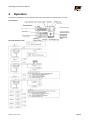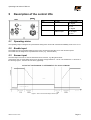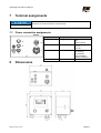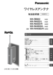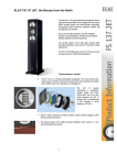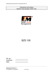
1
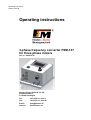
Operating instructions Status: 2012-09 Operating instructions 3-phase frequency converter FSM-137 for three-phase motors Art. no.: 90.0010.56 fimotec-fischer GmbH & Co. KG Friedhofstraße 13 D -78588 Denkingen Tel: Fax: +49 (0)74 24 - 88 4-0 +49 (0)74 24 - 88 4-50 E-mail: Internet: post@fimotec.de www.fimotec.de Operating instructions FSM-137 The duplication, sharing or use of this documentation or its contents is only allowed with written permission. Violations result in liability for damages. All rights reserved, including such which arise from granted patents or registration of a utility patent or design. Copyright © fimotec-fischer GmbH & Co. KG 2012 Page 2 Status as of 09 / 2012 Operating instructions FSM-137 Information and explanations Target group These operating instructions will help you to use the described product safely and as intended. They are directed toward qualified skilled personnel*. Qualified personnel are people who have been authorized by persons responsible for the safety of the system to execute the required activities and are able to recognize potential dangers and avoid them based on their training, experience and instruction, as well as their knowledge of standards, regulations, accident prevention regulations and operating conditions (definition of skilled personnel according to IEC 364). Read these operating instructions before you install the device, use it or carry out work on it. Also pass on these operating instructions to other users. Definition of the warnings and symbols Warnings are indicated by danger symbols and signal words. The table shows what hazards and possible consequences the symbols, signal words and colours indicate. Signal word ACHTUNG Definition Consequences Directly threatening danger Death or extremely serious injuries Dangerous situation Potential death or extremely serious injuries Dangerous situation Minor to moderately serious injuries Risk of property damage Damage to the machine, its environment and the product Warnings can also have other warning signs: Example: Warning of electrical current! These symbols indicate the type of hazard. Term definitions Term Definition User Persons who use the device installed by the manufacturer in its ready-touse version. Screen Designation for the image visible within the touchscreen. Button Designation for key fields on the user interface EMC Electromagnetic compatibility with electrical and electromagnetic influences. Skilled personnel Qualified personnel with the appropriate education, training and experience. Device Designation (in these operating instructions) for the frequency converter FS137. Machine manufacturer Persons who install the device in the intended construction (machine) and who manufacture the ready-to-use version. Menu Designation for the structural layout of the user interface. Status as of 09 / 2012 Page 3 Operating instructions FSM-137 Table of contents 1 PRODUCT OVERVIEW ......................................................................................................................... 5 1.1 Scope of delivery .................................................................................................................................... 5 1.2 Device versions ...................................................................................................................................... 5 1.3 Properties ............................................................................................................................................... 6 1.3.1 1.3.2 1.3.3 1.3.4 General ........................................................................................................................................................................................... 6 Output data ..................................................................................................................................................................................... 6 Inputs .............................................................................................................................................................................................. 6 Outputs ........................................................................................................................................................................................... 6 2 SAFETY INFORMATION ....................................................................................................................... 7 2.1 Intended use ........................................................................................................................................... 7 2.2 Basic safety information ......................................................................................................................... 7 2.2.1 Transport and storage .................................................................................................................................................................... 7 3 INSTALLATION ..................................................................................................................................... 8 3.1 Hardware installation .............................................................................................................................. 8 3.2 Mains connection ................................................................................................................................... 8 3.3 Oscillating conveyor connection ............................................................................................................. 8 3.4 Fuse protection ....................................................................................................................................... 8 4 OPERATION .......................................................................................................................................... 9 4.1 Acceleration times ................................................................................................................................ 10 4.2 Direction of rotation, motor ................................................................................................................... 10 4.3 External enable .................................................................................................................................... 10 4.4 Sensor input ......................................................................................................................................... 10 5 DESCRIPTION OF THE CONTROL I/OS ........................................................................................... 11 5.1 Operating status ................................................................................................................................... 11 5.2 Enable input.......................................................................................................................................... 11 5.3 Sensor input ......................................................................................................................................... 11 6 TECHNICAL DATA .............................................................................................................................. 12 7 TERMINAL ASSIGNMENTS ............................................................................................................... 13 7.1 Power connection assignments............................................................................................................ 13 8 DIMENSIONS ....................................................................................................................................... 13 9 MAINTENANCE AND CARE ............................................................................................................... 14 9.1 Regular tests ........................................................................................................................................ 14 9.2 Decommissioning and disposal ............................................................................................................ 14 10 ACCESSORIES AND OPTIONS ......................................................................................................... 14 9.1 The plug connectors listed below are available as accessories: ......................................................... 14 10.2 The connection lines listed below are available as accessories: ......................................................... 14 10 ACCESSORIES AND OPTIONS ...................................... FEHLER! TEXTMARKE NICHT DEFINIERT. Page 4 Status as of 09 / 2012 Operating instructions FSM-137 1 Product overview 1.1 Scope of delivery FSM-137 Operating instructions 1.2 Device versions The FSM-137 device is a 3-phase frequency converter for the sinusoidal actuation of consumers with variable frequency. Status as of 09 / 2012 Page 5 Operating instructions FSM-137 1.3 Properties 1.3.1 General Consumer output Parameterization via parameter blocks Operation via parameters Mains input voltage monitoring Type of protection IP54 1.3.2 1.3.3 Inputs Enable input for switching on/off without power Sensor input with switch-on/off delays in range of 0 to 20 seconds 1.3.4 Output data Frequency range 10 Hz to 60 Hz The frequency range is adjustable in steps of 0.01 Hz for all variants. Adjustable soft start ramp / soft stop ramp Adjustable switch-on/off delay Outputs Operating notification relay contact 250 V AC / 2.5 A (changeover contact). Consumer output for three-phase motor Page 6 Status as of 09 / 2012 Operating instructions FSM-137 2 Safety information 2.1 Intended use The FSM-137 device is a piece of electrical equipment intended for use in supply mechanisms or automation systems. The device is designed for regulating and controlling three-phase motors. The electrical components listed here are called "devices" in the industrial parlance, but are not devices which can be used or connected or machines in the sense of the "Device safety law", the "EMC law" or the "EC Machinery Directive", but components. Only when these components are integrated in the construction of the machine manufacturer is the ultimate mode of operation defined. The machine manufacturer is responsible for making sure that the construction meets the existing legal regulations. 2.2 Basic safety information The following warnings both serve for the personal safety of the user as well as the safety of the described products and the devices connected to them. Non-observance can lead to death, serious bodily injury or property damage. DANGER Life-threatening danger due to electric shock! Even after the device is put out of operation by disconnecting the voltage, there is still dangerous electrical voltage on the internal circuit parts. Disconnect the device from the supply voltage before any intervention. Before opening the device, wait for at least 5 minutes until the residual voltage has dissipated. Check to make sure there is no voltage before any intervention. Only skilled electricians may work on electrical equipment. Before commissioning, make sure that the voltage supply agrees with the nominal values of the device. Check the electrical equipment of the machine regularly. Deficiencies, such as loose connections, damaged or scorched lines, must be fixed immediately. Observe the valid accident prevention and safety regulations for your application. In particular, observe both the general and the regional installation and safety regulations for working with dangerous voltages (e.g. EN 50178) as well as the regulations having to do with the proper use of tools and the use of personal safety equipment. The Emergency Stop mechanisms must remain in effect in all operating modes. Unlocking the Emergency Stop mechanisms must not result in uncontrolled reactivation. 2.2.1 Transport and storage Problem-free and safe operation of this device require proper transport, storage, setup and installation, as well as careful operation and maintenance. The device must be protected against mechanical impacts and vibrations during transport and storage. Protection against moisture, water and impermissible temperatures (see chapter 6 "Technical data") must also be guaranteed. Status as of 09 / 2012 Page 7 Operating instructions FSM-137 3 Installation ATTENTION 3.1 If the device is not correctly connected, this can lead to the failure or complete destruction of the device (and the connected load). Hardware installation The FSM-137 device is designed for external installation (outside of the control cabinet) and has IP54 protection. If the device is mounted on a mounting plate made of metal, it can be installed with its entire area in contact with the plate or with spacers. If the device is mounted to a thermally non-conductive surface, it is to be mounted at a distance of at least 10 mm from its surface. 3.2 Mains connection The mains must be connected according to the valid regulations. It is connected via the attached Schuko "power" plug. All touchable, electrically conductive housing parts must be grounded according to the valid regulations. The connection must be made with at least a 1.0 mm² line cross-section. 3.3 Oscillating conveyor connection This is connected via the "X11" socket. The pin assignments are as follows: Pin 1 Connection for load (U) Pin 2 Connection for load (V) Pin 3 Connection for load (W) PE Connection for the ground protection conductor The three-phase motor is connected to this connection. 3.4 Fuse protection The fuse protection on the primary side depends on the line cross-section. However, it must be designed to have a B6 line protection switch at minimum. The devices are also protected with internal fuses. Caution!: Leakage currents against PE might occur due to EMC-related suppressor components. These are harmless, however, when an industry-standard RCD switch is used with a tripping current of 0.3 A. Page 8 Status as of 09 / 2012 Operating instructions FSM-137 4 Operation The device is operated via a power potentiometer and a user interface on the frequency converter. User interface: Key field navigation plan Status as of 09 / 2012 Page 9 Operating instructions FSM-137 4.1 Acceleration times In parameter F002, the acceleration time for the motor can be set. Setting range: 0.01 to 3600 s In parameter F003, the delay time for the motor can be set. Setting range: 0.01 to 3600 s 4.2 Direction of rotation, motor Setting the direction of rotation for the motor Fnct. code P100 4.3 Value Designation 0 1 Direction of rotation, clockwise Direction of rotation, counterclockwise Factory settings 0 External enable Setting the external enable Fnct. code P110 Value Designation 0 External enable Switching status N.O. "normally open", active when contact closed External enable Switching status N.C. "normally closed", active when contact open 1 4.4 Factory settings 1 Sensor input Setting the sensor functions Fnct. code P120 Value Designation 0 Sensor input Switching status N.O. "normally open", active when contact closed Sensor input Switching status N.C. "normally closed", active when contact open Switch-off delay, setting range 0…200 0.0…20.0 s Switch-on delay, setting range 0…200 0.0…20.0 s 1 P121 0…200 P122 0…200 Page 10 Factory settings 0 10 50 Status as of 09 / 2012 Operating instructions FSM-137 5 5.1 Description of the control I/Os Plug connection X21 Designation Enable X22 Sensor X23 Operation status output 1: +24 V DC 2: Signal 1: +24 V DC 2: 0 V 4: Signal 1: N.O. 2: Changer 3: N.C. Operating status The operating output is designed as a potential-free changeover contact with a maximum loadability of 250 V AC / 2.5 A. 5.2 Enable input The enable input is for powerless switching of the motor connected to the FSM-137 on and off without power. The enable must be designed via a potential-free contact. (e.g.: external switch) 5.3 Sensor input The load output of the FS-137 can be switched on/off via a sensor, e.g. filling level sensor. Via the menu, the on and off delay times can be set within a range between 0 – 20 sec. The resolution is 0.1 seconds. In the following Figure 1, the time curve is shown graphically. Figure 1: Time curve for load output, sensor input Status as of 09 / 2012 Page 11 Operating instructions FSM-137 6 Technical data Supply voltage: 200 - 240 V AC (other voltages possible after consultation) Mains frequency: 50/60 Hz (other frequencies possible after consultation) Output current "X11" 6.3 A Power 0.37 kW Enable Contact 24 V DC Load current, sensor: 24 V DC each, max. 80 mA Status output, potential-free changeover contact Changeover contact, 230 V AC / 6 A Operation: 7 segment display and function keys Type of protection: IP54 Permissible ambient temperature 5°C to 45°C Permissible relative humidity max.95 %, non-condensing. Dimensions: approx. (h)185 mm x (w)169 mm x (d)115 mm Page 12 Status as of 09 / 2012 Operating instructions FSM-137 7 Terminal assignments ATTENTION 7.1 8 If the device is not correctly connected, this can lead to the failure or complete destruction of the device (and the connected load). Power connection assignments Plug connection Power Designation Supply voltage X10 Mains output X11 Consumer output F1 Fuse 200 V AC…240 V AC 50 Hz / 60 Hz 1: 230 V AC 2: 0 V PE: PE 1: Load (U) 2: Load (V) 3: Load (W) PE: Protective ground conductor 6.3 A, slow-blow Dimensions Status as of 09 / 2012 Page 13 Operating instructions FSM-137 9 Maintenance and care 9.1 Regular tests The devices are usually maintenance-free. The electrical equipment of the machines are still to be checked regularly by skilled electricians. 9.2 Decommissioning and disposal The device is to be decommissioned by skilled electrical personnel while complying with the valid safety regulations. The packaging of the converter can be recycled. Please keep the packaging for later use. Easily removable screw connections allow the device to be disassembled into its components. These individual components can be recycled. Please carry out disposal in agreement with the local regulations. Problematic materials must not be thrown away in the normal waste! Dispose of problematic materials properly, safely and in an environmentally-friendly manner. 10 Accessories and options 9.1 The plug connectors listed below are available as accessories: Function Enable/disable connection Sensor connection Operating status output connection Mains output connection Slot X21 X22 X23 X10 Article number 91.3300.70 91.3300.40 91.3200.60 91.3300.20 10.2 The connection lines listed below are available as accessories: Function Mains output Belt conveyor connection Page 14 Length, line Slot X10 X11 Article number Status as of 09 / 2012