1
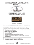
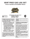
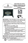
Tested &
Listed By
VMO24RNGA
Vented Decorative Appliances
for installation in Solid Fuel
Burning Fireplaces
For Use with
APPALACHIAN OAK LOGS
REMOTE CONTROL GAS LOG
VENTED DECORATIVE APPLIANCE
Convertible from Natural Gas to Propane/LP Gas
OWNER'S OPERATION AND INSTALLATION MANUAL
WARNING: If the information in this manual is not
followed exactly, a fire or explosion may result causing
property damage, personal injury or loss of life.
— Do not store or use gasoline or other flammable vapors
and liquids in the vicinity of this or any other appliance.
— WHAT TO DO IF YOU SMELL GAS
• Do not try to light any appliance.
• Do not touch any electrical switch; do not use any
phone in your building.
• Immediately call your gas supplier from a neighbor’s
phone. Follow the gas supplier’s instructions.
• If you cannot reach your gas supplier, call the fire
department.
— Installation and service must be performed by a qualified installer, service agency or the gas supplier.
INSTALLER: Leave this manual with the appliance.
CONSUMER: Retain this manual for future reference.
Safety ............................................................... 2-3
Product Identification ........................................... 3
Local Codes .........................................................4
Unpacking ............................................................4
Product Features ................................................. 4
Installation ............................ ........................ 4-10
..............
11
Operation .. ........................................................
Inspecting Burners ............................................ 12
Cleaning and Maintenance ................................13
Service Hints .....................................................13
Technical Service ...............................................13
Troubleshooting ...........................................13-14
Replacement Parts ......................................15-16
Warranty ............................................ Back Cover
SAFETY
WARNING: Improper installation, adjustment,
alteration, service, or maintenance can cause
injury or property damage. Refer to this manual for
correct installation and operational procedures. For assistance or additional information
consult a qualified installer, service agency,
or the gas supplier.
WARNING: This appliance is for installation
only in a solid-fuel burning masonry or UL127
factory-built fireplace, constructed of noncombustible material, and connected to a working
flue. (See page 5 for minimum flue opening.)
WARNING: This is a gas-fired appliance. It uses
air (oxygen) from the room in which it is installed.
Provisions for adequate combustion and ventilation air must be provided. Refer to the National
Fuel Gas Codes, ANSI Z233.1/NFPA54,Air for Combustion and Ventilation .
WARNING: This product contains chemicals known to the State of California to cause
cancer or birth defects, or other reproductive
harm.
WARNING: Keep flue open when operating
unit.
IMPORTANT: Read this owner’s manual carefully
and completely before trying to assemble, operate, or service this log set. Improper use of
this log set can cause serious injury or death
from burns, fire, explosion, electrical shock,
and carbon monoxide poisoning.
DANGER: Carbon monoxide poisoning may
lead to death!
2
Carbon Monoxide Poisoning:Early signs of carbon
monoxide poisoning resemble the flu, with headaches,
dizziness, or nausea. If you have these signs, the log
set may not be working properly. Get fresh air at once!
Have log set serviced. Some people are more affected
by carbon monoxide than others. These include pregnant
women, people with heart or lung disease or anemia,
those under the influence of alcohol, and those at high
altitudes.
Natural and Propane/LP Gas: Natural and propane/LP
gases are odorless. An odormaking agent is added to the
gas. The odor helps you detect a gas leak. However,
the odor added to the gas can fade. Gas may be present
even though no odor exists.
Make certain you read and understand all warnings.
Keep this manual for reference. It is your guide to safe
and proper operation of this log set.
WARNING: Any change to this log set or its controls can be dangerous.
1. This appliance, as supplied, is only for use with the
type of gas indicated on the rating plate. This appliance
is convertible for use with propane/LP. (see Conversion
Instruction, P.7 )
2. What to do if you smell gas:
• Shut off gas supply.
• Do not try to light any appliance.
• Do not touch any electrical switch; do not use any
phone in your building.
• Immediately call your gas supplier from a neighbor’s
phone. Follow the gas supplier’s instructions.
• If you cannot reach your gas supplier, call the fire
department.
3. Never install the log set:
• In a recreational vehicle
• Where curtains, furniture, clothing, or other flammable
objects are less than 42" from the front, top, or sides
o f t he log se t
• In high traffic area
• In windy or drafty areas
SAFETY
Continued
5. You must operate this log set with fireplace screens
in place and fully closed. Unless provided by other
means, fireplace doors or screens shall haveopenings for introduction of combustion air.
11. Do not run log set:
• where combustible materials, gasoline and other
flammable vapors and liquids are used or stored
• under dusty conditions
6. This log set is designed to be smokeless. If logs
ever appear to smoke, turn off appliance and call a
qualified service person.
Note: During initial operation, slight smoking could
occur due to log curing and the burning off of manufacturing residues. You may wish to add more
ventilation by opening a window.
7. To reduce the creation of soot,, follow the “Cleaning
and Maintenance” instructions on page 13.
12. Do not burn solid fuel in the fireplace after installing the log
set. Do not use this log set to cook food or burn paper or
other objects.
13. Log set becomes very hot when in use. Keep children and
adults away from hot surface to avoid burns or clothing
ignition. Log set will remain hot for a time after shut-down.
Allow surface to cool before touching.
14. Carefully supervise young children when they are in
the room with log set.
8. Do not allow fans to blow directly into the fireplace.
Avoid any drafts that alter burner flame patterns. Ceiling
fans can create drafts that alter burner flame patterns.
Altered burner patterns can increase sooting.
9. Do not use a blower insert, heat -exchanger insert or
other accessory not approved for use with this log
set.
10. The installation and provisions for combustion and ventilation air must conform with the National Fuel Gas
Codes, ANSI Z233.1/NFPA 54, Air for Combustion and
Ventilation.
15. Do not use this appliance if any part has been under
water. Immediately call a qualified service technician
to inspect the appliance and to replace any part of the
control system and any gas control which has been
under water.
16. To help prevent breakage, new logs must be broken-in
(see “Curing Logs” page 12).
17. Turn log set off and let cool before servicing, installing,
or repairing. Only a qualified service person should install, service, or repair log set.
18. Provide adequate clearances around air openings.
PRODUCT IDENTIFICATION
Heat Shield
Burner Tube
Burner Pan
Control Knob
Figure 1 - Product Identification - VMO24RNGA Shown
3
UNPACKING
LOCAL CODES
Install and use log set with care. Follow all local
codes. In the absence of local codes, use the
latest edition of The National Fuel Gas Code ANSIZ223.1/NFPA 54*.
CAUTION: Do not remove the metal data plates from the
burner pan. The data plates contain important warranty
and safety information.
.
*Available from:
American National Standards Institute, Inc.
1430 Broadway
New York, NY 10018
National Fire Protection Association, Inc.
Batterymarch Park
Quincy, MA 02269
1. Remove logs, hearth kit, pan materials,
and hardware from carton.
2. Remove all protective packaging applied
to logs and base for shipment.
3. Check appliance for any shipping damage.
If it is damaged call Sure Heat Manufacturing
at 1-800-229-5647 for replacement parts
before returning to dealer.
PRODUCT FEATURES
REMOTE CONTROL SAFETY VALVE/PILOT
This unit is provided with a remote gas control valve
which is connected to a wireless transmitter/receiver set, allowing safe operation from anywhere
in the room.
APPROVALS
Unit is tested and approved to ANSI Z21.60 as a vented
decorative appliance. It is supplied with the parts and instructions to convert to propane/LP gas use.
INSTALLATION
WARNING: The Massachusetts State
Board requires all installations be performed by a Licensed Plumber or Gas Fitter. Massachusetts state code requires all vent
dampers be welded open or removed.
CAUTION: Do not remove the data plates
attached to the burner pan. The data plates
contain important warranty and safety informat-
NOTICE: Installation, service, and repair of this appliance must
be performed by a qualified installer, service agency, company or gas supplier, experienced with this type of gas appliance. Only factory authorized components should be used,
in accordance with the manufacturer’s instructions and all
codes and requirements of the authority having jurisdiction.
Any modifications to this kit, or use of unauthorized components or accessory items will void the manufacturer’s warranty,
and may result in a hazardous condition.
ion.
WARNING: Before installing in a solid fuel
burning fireplace, the chimney flue and firebox
must be cleaned of soot, creosote, ashes and
loose paint by a qualified chimney cleaner.
Creosote will ignite if highly heated. A dirty chim ney flue may create and distribute soot within
the house. Inspect chimney flue for damage.
VENTING SPECIFICATIONS FOR
INSTALLATION
The fireplace chimney flue and vent must be drafting properly. To check the vent for proper drafting:
Light a tightly rolled newspaper on one end and
place it at the inside front edge of the fireplace.
Observe the smoke and be sure the vent is properly drawing it up the chimney. If the smoke spills
out into the room, extinguish the flame and remove
any obstruction until proper venting is achieved.
4
FLUE OPENING SPECIFICATIONS
Note: This vented appliance must be installed only in a
solid-fuel burning fireplace with a working flue and constructed of noncombustible material.
The chimney flue damper must be fixed open to provide a
minimum of 81 sq. in. of free air opening during operation
of this log set. A multipurpose damper clamp is provided
to fix the damper in position.
The minimum flue sizes shown in Figure 2 are based on
a 6' chimney height using round pipe. Your minimum flue
size will vary based on input rate and chimney height. Refer
to the National Fuel Gas Code ANSI Z223.1/NFPA 54,
Section 6.6, for details.
INSTALLATION
Continued
The charts in Figure 2 indicate technical information regarding the installation of your gas log set.
Please make sure that all of the specifications
shown are applicable before installation is attempted.
The fireplace must include a working flue and venting
system with the minimum openings shown in the
Figure 2.
LOG
SIZE
24"
MINIMUM FIREBOX SIZE
FRONT BACK
MINIMUM
WIDTH WIDTH* DEPTH HEIGHT FLUE SIZE
8" dia.
35 3/4"
17"
15 1/2"
18"
CHECK GAS TYPE
Use only natural gas. If your gas supply is not natural gas, you must convert the appliance to propane
/LP. Follow the instructions on page 7.
If the fireplace does not have a gas supply shutoff
valve, one must be installed.
INSTALLING DAMPER CLAMP
Secure the damper stop clamp provided to the leading
edge of the damper as shown in Figure 3. If for any reason this clamp doesn't work on your fireplace, another
suitable clamp or permanent stop must be installed, or
the damper blade must be cut or removed.
FUEL PRESSURE
SPECIFICATIONS (W.C.)
Inlet
Manifold*
NG 5.5"-10.5"
3.5"
LP
11"-13"
10"
* ± .2"
DESCRIPTION
24" Dual Burner
LOG
SIZE
24”
In.
.144
Btu\Hr Input
Natural Gas
60,000
Damper
Clamp
Damper
Damper
Clamp
Btu\Hr Input
Propane Gas
60,000
Damper
Damper
BURNER ORIFICE
NATURAL
PROPANE/LP
Num.
In.
Num.
#27
.089” #43
-
Figure 2 - Technical Information Charts
CONNECTING TO GAS SUPPLY
WARNING: A qualified service person must
connect log set to gas supply. Follow all
local codes.
Installation Items Needed
Before installing log set, make sure you have
the items listed below.
• piping (check local codes)
• sealant (resistant to propane/LP gas)
• equipment shutoff valve
• adjustable (crescent) wrench or pliers
• sediment trap
• tee joint
• pipe wrench
CAUTION: Use only new, black iron or
steel pipe. Internally-tinned copper tubing may
be used in certain areas. Check your local
codes. Use pipe of 1/2" diameter or greater to
allow proper gas volume to log set. If pipe is too
small, undue loss of volume will occur.
Masonry Fireplace
Manufactured Fireplace
Figure 3 - Attaching Damper Clamp
CONNECTING TO GAS SUPPLY
Continued
Installation must include an equipment shutoff valve with
"T" style handle, gas union and, for propane/LP gas only,
a plugged 1/8" NPT pressure tap. Locate NPT tap within
reach for test gauge hook up. NPT tap must be upstream
from log appliance (see Figure 4).
IMPORTANT: Install equipment shutoff valve in an accessible location. The equipment shutoff valve is for
turning on or shutting off the gas to the appliance.
Apply pipe joint sealant lightly to male NPT threads. This
will prevent excess sealant from going into pipe. Excess
sealant in pipe could result in a clogged burner injector.
WARNING: Use pipe joint sealant that is resistant
to liquid petroleum (LP) gas.
5
INSTALLATION
Continued
We recommend that you install a sediment trap in
the supply line as shown in Figure 4. Locate sediment
trap where it is within reach for cleaning. Install in piping
system between fuel supply and heater. Locate sediment trap where trapped matter is not likely to
freeze. A sediment trap traps moisture and contaminants. This keeps them from going into log set controls.
If sediment trap is not installed or is installed wrong,
log set may not run properly.
CSA Design-Certified
Equipment Shutoff Valve
With 1/8" NPT Tap*
From Gas
Meter (5"
W.C.** to
10.5" W.C.
Pressure)
Approved Flexible
Gas Hose (no longer
than 36" if required by
local codes)
3" Minimum
Tee Pipe Cap
Joint Nipple
4. Check all joints of gas supply-piping system.
Apply a noncorrosive leak detection fluid to all
joints. Bubbles forming show a leak.
5. Correct all leaks at once.
6. Reconnect log set and equipment shutoff valve
to gas supply. Check reconnected fittings for
leaks.
Test Pressures Equal To or Less Than 1/2
PSIG (3.5 kPa)
1. Close equipment shutoff valve (see
Figure 5).
2. Pressurize supply piping system by either using
compressed air or opening main gas valve located on or near gas meter.
- to equip ment
3. Check all joints from gas meter
shutoff valve (see Figure 5). Apply a noncorrosive leak detection fluid to all joints. Bubbles
forming show a leak.
4. Correct all leaks at once.
Equipment
Shutoff Valve
Sediment Trap
Figure 4 - Gas Connection
Gas Meter
* Purchase the optional CSA design-certified equipment
shutoff valve from your dealer. ** Minimum inlet pressure
for purpose of input adjustment.
CHECKING GAS CONNECTIONS
WARNING: Test all gas piping and connections, internal and external to unit, for leaks after installing
or servicing. Correct all leaks at once.
WARNING: Never use an open flame to check
for a leak. Apply a noncorrosive leak detection fluid to
all joints. Bubbles forming show a leak. Correct all
leaks at once.
PRESSURE TESTING GAS SUPPLY PIPING
S YSTEM
Test Pressures In Excess Of 1/2 PSIG (3.5 kPa)
1. Disconnect log set and its individual
equipment shutoff valve from gas supply piping system.
2. Cap off open end of gas pipe where
equipment shutoff valve was connected.
3. Pressurize supply piping system by either using compressed air or opening main gas valve located on or
near gas meter.
6
Figure 5 - Checking Gas Joints
HEARTH PAN I NSTALLATION
If using propane/LP gas, see Propane/LP
Gas Conversion page 7 before installing
hearth pan.
1. Place the burner pan assembly in the center
of the fireplace floor. Make sure the front of
pan faces forward.
2. Thread the gas supply fitting to the fire place
gas supply pipe. Adjust to most convenient
position.
3. Install the gas connector tube to the gas supply
adapter. Carefully shape tube and attach to gas
inlet fitting (see Figure 6). Be careful not to
cause kinks in tube.
4. Test for leaks following instructions under
Testing Burner for Leaks , page 8.
INSTALLATION
Continued
5.
Retighten and adjust the location of the
gas control as necessary. The gas control
should be level, with the control knob to the
front.
Be sure to use the correct orifice for your appliance. The orifice kit included with this appliance contains an orifice installed in an air
mixer fitting.
4.
Using thread sealant (resistant to the action
of propane/LP gas) on smaller end of fitting,
screw the burner inlet fitting into outlet side of
gas control. Tighten using a wrench.
5 . Rethread valve and fitting assembly into
burner tube until fully threaded and level with
burner pan. Reattach valve cover with two
(2) screws.
NATURAL GAS
COMPONENTS
Gas Control Valve
Natural Gas
Pilot Orifice
Figure 6 - Installing Inlet Fitting and Gas
Connector Tube (Heat Shield Removed
for Clarity)
SELECTING GAS TYPE
This appliance can be used with Propane/LP gas or
Natural Gas. It is shipped from the factory adjusted
for use with Natural Gas. Main burners are equipped
with fixed orifices, located at the inlet of the burner
pan (see Figure 7).
WARNING: Only a qualified installer or
service technician can perform gas conversion and connection to gas supply.
Propane/LP Gas Conversion
To convert to Propane/LP gas, the regulator press ure must be reset. Also, burner inlet fitting and
pilot orifice must be replaced. The Propane/ LP
burner inlet fitting is supplied with the orifice installed
for your log set.
Burner Inlet Fitting
1. Remove pilot assembly burner pan by removing two screws on bracket.
2. Unthread control valve and burner inlet fitting
from burner tube by turning valve counterclock
wise (see Figure 7) .
3. Remove Natural Gas inlet fitting from control
valve assembly (see Figure 8).
DO NOT remove orifice from this fitting. The
Propane/LP burner inlet fitting is provided in
the hardware kit (see Figure 8).
Retain the removed Natural Gas components
for future use.
Burner Inlet Fitting
for Natural Gas
Figure 7 - Burner Inlet Fitting and Pilot Prifice
Orifice for
Natural Gas
Injector for
Propane/LP Gas
NATURAL
GAS
FITTING
PROPANE/LP
GAS FITTING
Figure 8 - Burner Inlet Fittings shown with orifice
Pilot Orifice Replacement
Disconnect the pilot supply tube from the pilot (See
Figure 7). Replace the pilot orifice with the Propane/LP
pilot orifice included with the Gas conversion kit. Retain
the removed orifice for future use.
NG to LP Regulator Selection
The appliance regulator can be converted from Natural
Gas to LP/gas. If connecting to a Propane gas system,
the regulator must be switched prior to use. Follow the
steps below to select Propane/LP gas.
1. Carefully remove the logs from the burner assembly.
2. Make sure gas is turned off to the unit and disconnect
burner assembly from gas line. Remove burner assembly from fireplace or firebox.
3. Locate the regulator cap on the appliance regulator (see
Figure 9). Unscrew by hand and remove the cap from
the regulator. The pressure selecting screw is attached
to the regulator cap. The pressure selecting screw is
supplied in the Natural Gas position.
4. Unscrew and remove the pressure selecting screw
from the regulator cap (see Figure 9 ).
7
INSTALLATION
Continued
5. Turn pressure selecting screw over and reinstall it
in regulator cap (see Figure 10-11).This will set the
pressure selecting screw to the LP/Propane gas
ition. Makethe pressure selecting screw is installed
tightly to the regulator cap.
6. Replace the regulator cap on the appliance regulator.
Figure 10 - Removing Regulator Cap from Pressure
Selecting Screw
Pressure
Selecting
Screw
Appliance
Regulator
Regulator
Cap
Figure 9 - Gas Selection Valve Knob and
Regulator Cap
Figure 11 - Turning Pressure Selecting Screw Over/
Attaching to Regulator Cap – LP/Propane
Gas Position
NOTE: In order to convert the unit from LP Gas, back to Natural Gas, follow steps 1 through 3 under “Burner
Inlet Fitting” on page 7.Follow steps 1 through 6 under the heading of “NG to LP Regulator Selection” on
this page. Images 11 and 12 will occur in reverse order.
Testing Burner for Leaks
1. Generously apply soapy solution to all connections.
WARNING: Never check for gas
leaks with open flame.
2. Light burner with shutoff valve no more than half
open and holding a match slightly in front of pan
(see Lighting Instructions , page 11).
3. Inspect all connections for bubbles, raw gas odor,
or flame from any area other than the burner (leaks).
If leaks are detected, shut off gas valve immediately.
tighten, or reassemble loose connection(s) using pipe
joint compound until burner system is leak free.
4. When burner is tested and leak free, observe
individual tongues of flame on burner (from ports).
Note: Make sure that all ports are clear and producing flame evenly across burner. If any ports appear
blocked, clear them by removing burner manifold and
8
-
reaming ports with a modified paper clip or other suitable tool. When finished testing, turn gas shutoff
valve to OFF to extinguish all flames.
Adding Burner Media Material
1. Open bag of burner media material (vermiculite
if set for LP/Propane) and spread it evenly
across burner pan to the top. You may overflow front and sides of pan to cover entire pan.
Do not cover valve.
2. Open glowing embers and evenly cover burner
media material (or vermiculite) in burner pan.
Installing Grate and logs
1. Slide two rear log grate steps over two outer
horizontal supports on t h e grate as shown
in image 2 on page 9.
2. Install logs onto the grate by following the rest
of the instructions in on pages 9 and10.
LOG PLACEMENT
VMO24RNGA
1
8
2
9
10
4
6
7
3
5
Log Identification
Back Log Stand-Offs in place
2
1
Place main front log (1)
onto front area of the grate
Place shorter back log (2)
onto raised area of the grate
4
3
Place Cross-Log (3) at the left side
Place Cross-Log (4) at the center right
5
6
Place Cross-Log (5) atop (3) and (4) at
the back left
Place Cross-Log (6) atop (3) and (1)
on the left side front.
9
LOG PLACEMENT
VMO24RNGA
Continued
7
Place Cross-Log (7) at the top back, on
the right side
9
8
Place Cross-Log (8) atop (1) and (7) at
the center right
10
Place smallest decorative logs (9) and (10) onto the fireplace
floor at each end of burner pan
WARNING: Failure to position the parts in accordance with these diagrams or failure to
use only parts specifically approved with this appliance may result in property damage
or personal injury.
10
OPERATION
FOR YOUR SAFETY
READ BEFORE LIGHTING
WARNING: Keep flue open when operating unit.
WARNING: If you do not follow these instructions exactly, a fire or explosion may result causing property damage, personal injury or loss of life.
A. This appliance has a pilot which must be lighted
by hand. When lighting the pilot, follow these
instructions exactly.
B. BEFORE LIGHTING smell all around the appliance area for gas. Be sure to smell next to the
floor because some gas is heavier than air and
will settle on the floor.
WHAT TO DO IF YOU SMELL GAS
• Do not try to light any appliance.
• Do not touch any electric switch; do not use
any phone in your building.
• Immediately call your gas supplier from a
neighbor’s phone. Follow the gas supplier’s instructions.
• If you cannot reach your gas supplier, call the
fire department.
Thermopile
Pilot
Figure 12 - Thermopile and Pilot
1. STOP! Read the safety information on the
left side of this page.
2. Make sure equipment shutoff valve is fully
open.
3. Press in and turn control knob clockwise
to the OFF position.
4. Wait five (5) minutes to clear out any gas.
Then smell for gas, including near the floor.
If you smell gas, STOP! Follow “B” in the safety
information, page 11. If you don’t smell gas, go
to the next step.
- counter clockwise
5. Press in and turn control knob
to the PILOT position.
Press in control knob for five (5) seconds (see
Figure 13).
Note: You may be running this log set for the first
time after hooking up to gas supply. If so, the control knob may need to be pressed in for 30 seconds
or more. This will allow air to bleed from the gas
system.
6. With control knob pressed in, use a match or
grill lighter to light pilot. Visually locate the pilot
(see Figure 12) on the edge of the burner pan
to look for flame.If needed, repete operation
until the pilot lights.
Control Knob
ON
PILOT
C. Use only your hand to push in or turn the gas
control knob. Never use tools. If the knob will
not push in or turn by hand, don’t try to repair it,
call a qualified service technician or gas supplier.
Force or attempted repair may result in a fire or
explosion.
D. Do not use this appliance if any part has been
under water. Immediately call a qualified service
technician to inspect the appliance and to replace
any part of the control system and any gas control
which has been under water.
LIGHTING INSTRUCTION
Figure 13 - Control Knob Location
7. If the pilot will not stay lit after several tries, turn
the gas control knob to "OFF" and call your service
technician or gas supplier.
8. Keep control knob pressed in- for 30 seconds
after lighting pilot. After 30 seconds, release
•control knob.
If control knob does not pop out when released,
contact a qualified service person or gas supplier for repairs.
Note: If pilot goes out, repeat steps 3
through 8.
11
LIGHTING INSTRUCTION
Continued
9. Slightly push in and turn control- knob counterclockwise
to the ON position.
10.To leave pilot lit and shut off burners only:
to the PILOT
Turn control knob clockwise
position, or set selector switch in the OFF position.
TO TURN OFF GAS
TO APPLIANCE
Shutting Off Appliance
1. Slightly push in and turn control knob clockwise
to the OFF position.
2. Close equipment shutoff valve.
CURING
THE LOGS
During the 2-3 hour appliance break-in period, you may
detect an odor from the appliance as the various paints
and compounds used in the manufacturing of this log
set cure.
This is a normal and temporary situation that is not
cause for alarm. However, you may want to provide
extra ventilation to the room during this time.
Hand Held
Remote
NOTICE: You must light the pilot before using the
hand-held remote control unit. See Lighting
Instructions, page 11.
After lighting, let pilot flame burn for about one minute.
Turn control knob to ON position. Slide the selector
switch on the remote receiver to the REMOTE
position.
Note: The burner may light if hand-held remote was
on when selector switch was last turned off. You
can now turn the burner on and off with the handheld remote control unit.
IMPORTANT: Do not leave the selector switch in the
REMOTE or ON position when the pilot is not lit.
This will drain the battery.
INSPECTING BURNERS
Check pilot flame pattern and burner flame patterns
often.
Pilot
Adjustment Screw
PILOT FLAME
The pilot assembly is factory preset for the proper
flame height. Alterations may have occurred during
shipping and handling. The pilot is located on the
back right hand side of the burner.
The thermocouple should be fully enveloped in the
flame. The flame should not be lifting off of the
thermocouple element.
If your pilot assembly does not meet these requirements:
• Turn the adjustment screw marked pilot clockwise
to decrease or counterclockwise to increase the
flame to proper size (see Figure 14).
Do not attempt to remove the adjustment screw.
• SeeTroubleshooting, pages 13-14
Figure 14 - Locating Pilot Adjustment Screw
BURNER FLAME PATTERN
Burner flames will be steady; not lifting or floating.
Flames should go up through the middle of logset.
Flames should not "spill" to the edges of the pan or
sides of the logset.
Figure 15 shows a typical flame pattern. If burner
flame pattern differs from that described:
• Turn appliance off (see To Turn Off Gas to Appliance, this page).
• See Troubleshooting , page14.
Thermocouple
Pilot
Figure 13 - Correct Pilot Flame Pattern
12
Figure 15 - Typical Flame Pattern
CLEANING AND MAINTENANCE
• Keep the area around the log set clean and clear of
debris.
• Occasionally, you may use a soft bristle brush to
clean logs.
• Periodically inspect the air mixer and burner tube for
foreign matter blocking the air inlet and flame holes.
• Once every year a qualified agency or certified chimney sweep should examine and clean the venting
system of the fireplace.
SERVICE HINTS
When Gas Pressure is Too Low
• pilot will not stay lit
• burners will have delayed ignition
• heater will not produce specified heat
• propane/LP gas supply may be low
If you suspect your gas pressure is too low, contact
your gas providerer and request that it be tested.
TECHNICAL SERVICE
For operational questions or technical service, call toll free (800) 229-5647. Be sure to have your model
number availible when calling.
TROUBLESHOOTING
WARNING: Turn off log set and let cool before servicing. Only a qualified service person should service
and repair log set.
OBSERVED PROBLEM
When attempting to ignite with a
match,pilot will not light.
POSSIBLE CAUSE
1. Gas supply turned off or
equipment shutoff valve
closed.
2. Control knob not in PILOT
position.
3. Control knob not pressed in
while in PILOT position.
4. Air in gas lines when installed.
5. Pilot adjustment screw
closed.
6. Pilot is clogged.
7. Low/incorrect gas pressure.
Pilot lights but flame goes
out when control knob is
released.
1.Control knob not fully
pressed in.
2.Control knob not pressed in
long enough.
3.Equipment shutoff valve not
fully open.
4.Pilot flame not touching
thermocouple, which
al
lows thermocouple to cool,
causing pilot flame to go
out. This problem could be
caused by one or both of
the following:
A) Low gas pressure
B) Dirty or partially clogged
pilot
5.Thermocouple connection
loose at control valve.
6.Thermocouple damaged.
7.Control valve damaged.
Burner does not light after
pilot is lit.
1.Burner orifice clogged.
2.Inlet gas pressure is too
low.
3.Thermocouple leads dis connected or improperly
connected.
REMEDY
1.Turn on gas supply or open
equipment shutoff valve.
2.Turn control knob to PILOT
position.
3.Press in control knob while
in PILOT position.
- con
4.Continue holding down
trol knob. Repeat igniting op eration until air is removed.
5.Adjust pilot flame for ap proximately 2" blue flame.
6.Clean pilot (see Cleaning
and Maintenance, above)
or replace pilot assembly.
7.Check/replace gas regulator.
1.Press in control knob fully.
2.After pilot lights, keep
- con
trol knob pressed in 30
seconds.
3.Fully open equipment
- shut
off valve.
4.A) Contact local natural gas
company.
B) Clean pilot (see Cleaning
and Maintenance, above)
or replace pilot assembly.
5.Hand tighten until snug, then
tighten 1/4 turn more.
6.Replace thermocouple.
7.Replace control valve.
1.Clean burner orifice.
2.Contact local natural or
propane/LP gas company.
3.Reconnect leads.
13
TROUBLESHOOTING
OBSERVED PROBLEM
Delayed ignition burner.
Continued
POSSIBLE CAUSE
1.Pilot flame needs adjust ing.
2.Wrong pilot orifice for gas
type.
Remote does not function.
Battery is not installed. Battery power
may be low.
Burner flame is too low or
too high.
1. Incorrect gas supply or pressure.
2. Blocked burner orifice or burner
manifold ports.
3. Improper burner orifice size.
REMEDY
1. Adjust pilot flame for ap proximately 2" blue flame.
2. Replace pilot orifice.
Replace 9-volt batteries in receiver
and/or remote control.
1.Check for proper gas supply
pressure.
2.Free burner orifice and
manifold ports of any burrs,
paint, or other blockage.
3.Verify proper burner orifice
sizing (see Figure 2, page 5).
Burner is excessively noisy.
(Note: The movement and
combustion of gas will cre
ate low, unavoidable levels
of noise.)
1.Passage of air/gas across irregular
surfaces.
2.Excessive gas pressure on natural
gas units.
1.Relieve any tight bends or
kinks in gas supply line.
2.Have inlet gas pressure
checked by a qualified ser
vice person.
Log set is smoking/sooting
excessively.
(Note: It is natural and unavoidable for vented gas log
sets to produce moderate
levels of carbon (soot) where
flames contact the logs. This
is especially true with propane/
LP gas.)
1.Poor fuel quality.
1. Contact local natural or
propane/LP gas company.
2. Adjust damper wide open
and/or have fireplace and
venting professionally
cleaned and checked.
3. Separate the logs to allow
more flame passage.
4. Remove any foreign items
from the flame pattern and/
or check for proper orifice
sizing.
5. Preheat flue in very cold
weather.
2.Fireplace venting system not
drafting properly.
3. Excessive flame impingement
or blockage.
4. Improper fuel/air mixture.
5. Excessive gas supply/pressure.
Log set produces a clicking/
ticking noise just after burner
is lit or shut off.
Metal expanding while
heating or contracting while
cooling.
This is normal with most log
sets. If noise is excessive,
contact qualified service
person.
Log set produces unwanted
odors.
1. Log Set burning vapors
from paint, hair spray, glues,
cleaners, chemicals, new
carpet, etc. (See IMPOR TANT statement below.)
2. Gas leak. See Warning
statement below.
1. Open flue to maximum. Stop
using odor causing products
while log set is running.
Gas odor even when control
knob is in OFF position.
1. Gas leak.See Warning
statement below.
2. Control valve defective.
•
•
•
•
•
2. Locate and correct all leaks
(see Checking Gas Connections, page 6).
1. Locate and correct all leaks
(see Checking Gas Connec tions, page 6).
2. Replace control valve.
WARNING: If you smell gas:
Shut off gas supply.
Do not try to light any appliance.
Do not touch any electrical switch; do not use any phone in your building.
Immediately call your gas supplier from a neighbor’s phone. Follow the gas supplier’s instructions.
If you cannot reach your gas supplier, call the fire department.
IMPORTANT: Operating log set where impurities in air exist may create odors. Cleaning supplies, paint, paint
remover, cigarette smoke, cements and glues, new carpet or textiles, etc. create fumes. These fumes may mix
with combustion air and create odors. These odors will disappear over time.
14
VMO24RNG(LP)A PARTS
22
21
24
2
19
23
18
20
19
7
1
27
6
28
5
4
16
LP Conversion
3
L
8
15
17
9
25
14
11
13
12
10
26
28
15
VMO24RNG(LP)A PARTS
Continued
KEY NO.
DESCRIPTION
QTY.
1.
SBNCJ00365A
Burner Pan
1
2.
RCOCB00002A
Burner Tube
1
3.
RMH-120-00085B
Orifice Holder, Natural Gas
1
4.
RMH-120-90955
Orifice, Natural Gas
1
5.
RMH-120-00084B
Orifice, Propane/LP Gas
1
6.
RMH-120-00324
Orifice, Propane/LP Gas
1
7.
RCODZ00145A
Washer
1
8.
RMH-120-00574
Pal Nut
1
9.
RMH-120-00069
Elbow, “Street” 3/8”NPT
2
10.
RMH-120-AF1010
Valve, Remote “ON/OFF”
1
11.
RMH-120-RVS304
Heat Shield
1
12.
RMH-120-90860
Pipe, “Close” 3/8” NPT
1
13.
RCOZZ00568A
Regulator, Dual Fuel
1
14.
RMH-120-00050
Fitting, 3/8” NPT X 3/8” Flare
1
15.
KHH-ACT16
Connector, 3/8” Tube
1
16.
FCHD1809021
Fitting, 3/8” X 1/2” NPT Female
1
17.
RMH-120-00571
Screw #6 32 x 1/2”
1
18.
RCOZZ00495B
Pilot Assembly, NG
1
19.
RMH-120-00570
Screw, Sheet Metal #6 x 1/2”
3
20.
RMH-120-PBAGA
Pilot Bracket
1
21.
RCORJ00003A
Grate, Vented
1
22.
SPSCJ00106A
Standoff, Back Log
2
23.
RMH-120-00420
Burner Spacer
1
24.
RMH-120-00100
Damper Clamp
1
25.
RCAF-1001
Remote Set (Transmitter and Receiver)
1
26.
RS1A
Heat Shield, Receiver
1
27.
RMH-130-00310
Vermiculite Granules (LP Media)
1
28.
ACC16
Glowing Embers
1
WIP-130-00010
Burner Media, Natural Gas
1
Not Shown
16
PART NO.
NOTES
______________________________________________________
______________________________________________________
______________________________________________________
______________________________________________________
______________________________________________________
______________________________________________________
______________________________________________________
______________________________________________________
______________________________________________________
______________________________________________________
______________________________________________________
______________________________________________________
_____________________________________________________
______________________________________________________
______________________________________________________
______________________________________________________
______________________________________________________
______________________________________________________
______________________________________________________
______________________________________________________
______________________________________________________
______________________________________________________
______________________________________________________
______________________________________________________
______________________________________________________
_____________________________________________________
______________________________________________________
______________________________________________________
______________________________________________________
______________________________________________________
______________________________________________________
______________________________________________________
______________________________________________________
______________________________________________________
17
NOTES:
NOTES:
LIMITED WARRANTY
Sure Heat Mfg. warran ts that the components of this appliance are warranted free from
defects in material and workmanship for one (1) year from the date of purchase. Sure
Heat Mfg.at its option, will repair or replace this product or any component of the product
found to be defective during the warranty period. Replacement will be made with a new
manufactured product or component. If the product is no longer available, replacement may
be made with a similar product of equal value.This warranty does not include transportation
.
or shipping costs of any kind. This is your exclusive warranty.
This warranty is valid for the original retail purchaser from the date of initial retail purchase
and is not transferable. Keep the original sales receipt. Proof of purchase is required to
obtain warranty parts.
This warranty does not cover normal wear of parts such as scratches and dents of the
components or damage resulting from any of the following:
• negligent use or misuse of the product, including exposing the product to chemicals or cleaning products
not approved by Sure Heat Mfg.
• corrosion, rust or discoloring of any kind
• use or installation contrary to specified instructions and applicable building codes, including heating the
product to temperatures above its rated specifi cations which can cause considerable warping
disassembly,
including removal of the product from a built-in installation
•
• damage resulting from accident, alteration, misuse, abuse, hostile environments, or improper installation
• repair or alteration
• acts of God, such as fire, flood, hurricanes, and tornadoes
• gas cylinders,propane tanks or other fuel deliverysystems, including connections to a household fuel
supply
• usage other than single-family household use such as commercial or industrial use
• minor warping or discoloration of parts, which is normal and not a defect under this warranty
DO NOT RETURN THIS PRODUCT TO THE PLACE OF PURCHASE
If the appliance does not operate properly , first thoroughly carry out the instructions
provided with the unit to ensure that the appliance is installed correctly and check the
troubleshooting section in this use and care manual.
We recommend you return this warranty registration card so that you can be contacted
should any questions of safety arise that could affect you. The return of the warranty
registration card is not a condition for warranty coverage.
Purchased From: _____________________________________ Date: ____________
Model: VMO24R(NG,LP)A
Serial Number: ____________________
Name: ______________________________ Phone Number: ___________________
Address: _____________________________________________________________
City: _________________________________ State: ________ ZIP: _____________
Because of continuing product improvement, these specifications are subject to change
without notice.
If you have other questions or need replacement parts contact our
Customer Service Hotline at (800) 229-5647 or
visit our website at www.sureheat.com
Sure Heat Manufacturing, 3140 Moon Station Road, Kennesaw GA, 30144
RMH-130-OMRCV
Rev1.1 06-2014