1
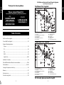
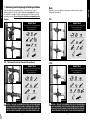
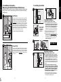
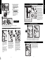
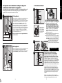
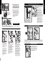
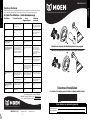
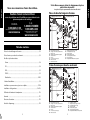
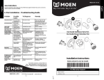
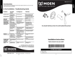
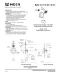
INS2150A - 9/11
To preserve the finish on the metallic parts of your Moen faucet, apply non-abrasive wax, such as car wax.
Any cleaners should be rinsed off immediately.
6. Post Installation - Troubleshooting Guide
Problem
Possible
Cause
Hot/cold reversed
Lines reversed/
cartridge installed
upside down
Hot/cold reversed
Rotate cartridge stem 180˚
so that the notch is facing
down towards the drain.
No water/low flow
One or both
supplies not on
to the unit
No water/low flow
Turn both water supply valves
counterclockwise to the on
position
Leak or drip
from spout
Grommets not
sealing properly
Leak/drip from spout
Replace cartridge
Only hot/no cold –
Only cold/no hot
Balancing spool
stuck
Only hot/no cold –
Only cold/no hot
Replace cartridge
Stacking (Water
comes out of the
showerhead during
tub fill mode)
Choice of pipe/
Water comes out of spout
distance between
and showerhead at the
valve and showerhead same time
less than 46"/multiple
elbows/anything
restricting flow of
water exiting valve
Change pipe to IPS or
copper/distance from
showerhead and valve
moved to at least 46"/
change or remove anything
restrictive
Flow restriction
between valve and
tub spout
Water comes out of spout
and showerhead at the
same time causing
restriction
Remove tub spout and flush
out debris – Replace
undersized line or fittings
Valve installed
upside down
Remove cartridge and verify
that the outlet hole is in
proper location (should be
down). "Up" is on the top
of the valve
Remove valve and reinstall
in the proper orientation
Handle (more
common in knob
models) is installed
upside down
In the off position, able to
turn the handle both
clockwise and
counterclockwise
Remove handle, rotate 180˚,
re-install
Temperature limit
stop out of position
Remove handle and
see Step 5.3
Position temperature limit
stop to desired temperature
position
Not able to install
handle/handle
rubs up against
escutcheon
Valve installed too far
back from finished
wall
Handle does not install
Contact Moen for assistance.
Handle is hard
to turn
Cartridge stem is
difficult to rotate
Difficult movement from
handle
Replace cartridge
or lubricate
Restricted
temperature range
To Diagnose
Remedy
▲
One Handle Tub/Shower Valve Trim
One Handle Shower Only Valve Trim
▲
English
English
Care Instructions
Installation Instructions
Styles and parts vary by model.
For further assistance, contact Moen at:
USA: 1-800-289-6636 or visit www.moen.com
Canada: 1-800-465-6130 or visit www.moen.ca
For Warranty Support
Model Number
INS2150A - 9/11
©2011 Moen Incorporated
E12
www.moen.com
Installation Date
E1
Visit Moen.com for product specific parts diagrams.
Styles and parts vary by model.
Tub/Shower Parts Supplied
A
Please Contact Moen First
Installs behind wall.
English
English
Thank you for choosing Moen.
Installs on wall exterior.
B
H
C
I
For Installation Help, Missing or Replacement Parts
USA
CANADA
1-800-BUY-MOEN
1-800-289-6636
Mon. - Fri. 8:00 a.m. to 8:00 p.m. EST
D
1-800-465-6130
Mon. - Fri. 7:30 a.m. to 5:00 p.m. EST
www.moen.ca
Sat. 9:00 a.m. to 5:30 p.m. EST
www.moen.com
J
E
K
F
L
P
x2 G
M
N
O
Table of Contents
Tub/Shower Parts Supplied................................................................................................E3
Shower Only Parts Supplied ..............................................................................................E3
Rough-in Plumbing Variations
A.
B.
C.
D.
E.
F.
G.
H.
Showerhead
Lever Handle Adapter
Adapter Screw (1/2”)
Lever Handle
Hex Screw
7/64” Hex Wrench
Tub Spout
Product Identification Label
Shower Only Parts Supplied
A
Copper ..................................................................................................................................E4
I.
J.
K.
L.
M.
N.
O.
P.
Shower Arm Flange
4 Port Valve and Stop Tube
Key Stop
Adjustable Temperature Limit Stop
Plaster Ground
Escutcheon
Escutcheon Screws (2-3/16”)
Shower Arm
Installs behind wall.
Installs on wall exterior.
B
H
C
I
IPS............................................................................................................................................E4
PEX ..........................................................................................................................................E5
D
J
Helpful Tools..................................................................................................................E4-E5
E
K
Installation Schematics ........................................................................................................E6
F
L
CVPC ......................................................................................................................................E5
Thin Wall/Thick Wall and Plaster Ground Installation ........................................E7-E8
x2 G
M
P
Trim Installation ............................................................................................................E8-E10
Setting the Temperature Limit Stop ............................................................................ E10
Warranty..................................................................................................................................E11
Care Instructions ..................................................................................................................E12
Troubleshooting Guide......................................................................................................E12
A.
B.
C.
D.
E.
F.
G.
H.
I.
J.
K.
L.
M.
N.
P.
Shower Arm Flange
3 Port Valve and Stop Tube
Key Stop
Adjustable Temperature Limit Stop
Plaster Ground
Escutcheon
Escutcheon Screws (2-3/16”)
Shower Arm
N
Showerhead
Lever Handle Adapter
Adapter Screw (1/2”)
Lever Handle
Hex Screw
7/64” Hex Wrench
Product Identification Label
For trim only, please proceed to step E8.
E2
E3
English
Note:
If you are replacing your plumbing valve, see below for four common
plumbing methods. Specific rough-in fittings are not supplied. These may
be required for installation. Remove existing handle and valve trim before
replacing your valve. Please follow all local building and plumbing codes.
Depending on your installation configuration, additional pipe and pipe
fittings may be required.
Copper
PEX
Helpful Tools
Helpful Tools
For safety and ease of faucet replacement,
Moen recommends the use
of these helpful tools.
For safety and ease of faucet replacement,
Moen recommends the use
of these helpful tools.
Safety Glasses
Measuring Tape
Pi p e J o i n t
Co m po u nd
Torch
Safety Glasses
Front View
Measuring Tape
Pipe Joint Compound
Front View
Wire Brush
Phillips Screwdriver
Tube Cutter
Crescent Wrench Thread Seal Tape Phillips Screwdriver
Lead-free Solder Kit
Thermometer
Thread Seal Tape
Full Circle Crimping Tool Thermometer
Pi p e J o i n t
Co m po u nd
Crescent Wrench
Back View
Flashlight
Tubing Cutter
Pipe Joint Compound
IPS – (Galvanized Iron Pipe/Threaded Connections)
Flashlight
Back View
Key Hole Saw
Key Hole Saw
CPVC
Helpful Tools
Helpful Tools
For safety and ease of faucet replacement,
Moen recommends the use
of these helpful tools.
For safety and ease of faucet replacement,
Moen recommends the use
of these helpful tools.
Pi p e J o i n t
Co m po u nd
Safety Glasses
Front View
Measuring Tape
Thermometer
Safety Glasses
Front View
Crescent Wrench
Crescent Wrench Thread Seal Tape Phillips Screwdriver
Back View
Flashlight
CAUTION – TURN HOT & COLD WATER SUPPLIES OFF BEFORE REMOVING YOUR CURRENT FAUCET OR DISASSEMBLING YOUR CURRENT
VALVE. OPEN FAUCET HANDLE TO RELIEVE WATER PRESSURE AND
ENSURE COMPLETE WATER SHUT-OFF HAS BEEN ACCOMPLISHED.
E4
Thread Seal Tape Phillips Screwdriver
CPVC Cement Thermometer CPVC Cleaner Tubing Cutter
Pipe Joint Compound
Key Hole Saw
Pipe Joint Compound
CPVC
C le a n er
CPVC
C e m e nt
Pi p e J o i n t
Co m po u nd
Adjustable Wrench
Measuring Tape
Flashlight
Back View
Key Hole Saw
CAUTION – TURN HOT & COLD WATER SUPPLIES OFF BEFORE REMOVING YOUR CURRENT FAUCET OR DISASSEMBLING YOUR CURRENT
VALVE. OPEN FAUCET HANDLE TO RELIEVE WATER PRESSURE AND
ENSURE COMPLETE WATER SHUT-OFF HAS BEEN ACCOMPLISHED.
E5
English
1. Determining Your Existing Rough-In Plumbing Installation
English
Installation of this product at non-recommended measurements may
lead to issues such as water discharge from the showerhead during
tub fill mode.
2.1
3. Installing Your Valve
3.2
3.1
less than 1/4"
(6mm)
Tub/Shower
78” (1981mm)
2-1/4" min.
(57mm)
3-1/2" max.
(89mm)
E
Use 1/2” Copper or
IPS Pipe Only
3.3
B
1
Shower Only
78” (1981mm)
2
Secure
escutcheon
to wall.
Go To Step 4.1
3
F
G
Thick Wall Installation
For Walls Thicker Than 1/4 inch
3.4
more than 1/4"
(6mm)
45-48”
(1143-1219mm)
4-1/2"
(114mm)
E
E6
(Wall)
F
P
The center of the valve should be 45 inches to 48 inches
above the shower stall floor. The shower arm should be
placed 78 inches above the floor of the shower stall floor
(recommended installation of the shower arm is with a
flanged elbow fitting – not included – and attached to a
wood brace).
Thin Wall Installation
For Walls Thinner Than 1/4 inch
3.1 The “Thin Wall” method is used when the
tub/shower wall is less than 1/4 inches thick
(such as fiberglass tub surround) and will
be the main source of support for the valve.
Ensure cartridge
The plaster ground (E) remains attached to
retainer clip is
the valve. A 2-1/4 inches to 3-1/2 inches diaminstalled prior
eter hole is cut thru the wall for this method.
to escutcheon
3.2 Break away the black plastic protective cover
installation.
using pliers and rotating clockwise.
3.3 Remove the escutcheon screws (G), place product
identification label (P) on back of escutcheon, make
sure wall is clean, place the escutcheon (F) over the
stop tube (B), then reinstall the screws (G). A gasket
on the back of the escutcheon provides a seal
against the finished wall.
32” (813mm)
2.2
E
3/4"
(19mm)
Position the valve body 32 inches from the floor of the
tub basin. The shower arm should be placed 78 inches
above the floor of the tub basin (recommended installation of the shower arm is with a flanged elbow fitting –
not included – and attached to a wood brace). The tub
spout is to be no less than 6 inches and no greater than
11 inches below the valve. If installing a threaded tub
spout, connect to the valve with 1/2 inch pipe or 1/2 inch
copper tubing with a threaded adapter. If installing a
slip-fit tub spout, connect to the valve with only copper
tubing – no threaded adapter is needed.
See step 4.3 for tub spout tube length.
6” (152mm) Min.
9” (229mm) Max.
English
2. Installation Schematics –
Measuring for Ideal Tub/Shower Performance
3.4 The “Thick Wall” installation method is used when
the tub/shower wall is greater than 1/4 inches thick.
“Thick Walls” are usually built up with materials such as
cement board, drywall, tile, etc. The valve is secured by
straps (not included) holding the water inlet lines to
the framing members (2X4’s) as shown in steps 2.1 and
2.2. The valve also features mounting holes to screw the
valve to a cross member attached behind the valve if
desired.
Attach the plaster ground (E) to the valve body
using the 2-3/16 inches escutcheon screws (G). Keep
the plaster ground (E) attached to the valve until the
valve has been positioned and secured. The plaster
ground (E) is positioned so that it is flush with the
finished wall. This ensures that the valve will be at
the correct position to accept the trim.
The hole in the wall should be the same size (4-1/2
inches) as the plaster ground (E). This hole will allow
access for future servicing if necessary.
E7
3.5
Threaded Tub Spout Installation
3.5 Once the valve is secured in place,
remove the escutcheon screws
(G) and the plaster ground (E).
Keep the escutcheon screws (G)
for installation of the escutcheon
(F) and discard the plaster
ground (E).
3.6 Place product identification label
(P) on back of escutcheon, make
sure wall is clean, place the
escutcheon (F) over the stop tube
(B) then re-install the screws (G).
A gasket on the back of the
escutcheon provides a seal
against the wall.
G
Ensure cartridge
retainer clip is
installed prior to
escutcheon
installation.
4.3A
If this is a shower only
installation, skip to step 4.4.
Tub Spout Installation
O
1
Thread seal tape
2
x
3.6
y
B
(Wall)
Secure
escutcheon
to wall.
(y) + (x) + 1/4” = Pipe Length
F
P
1
2
To determine the proper pipe length, measure from the inside elbow
shoulder to the wall (y) and from the threaded adapter inside of the
tub spout to the base of the tub spout (x), then add 1/4”.
Go To Step 4.1
IPS (threaded) spouts are
designed to screw onto a
pipe with 1/2 inch male pipe
threads. To determine the
proper pipe length, measure
from the inside elbow shoulder to the wall (y) and from
the threaded adapter inside
of the tub spout to the base
of the tub spout (x), then add
1/4”. Place thread seal tape
around the pipe threading
and a sealant (plumbers putty
or caulk) around the base of
the pipe to prevent leaking
behind the wall.
3
F
Slip Fit Tub Spout Installation
G
4.3B
Moen suggests testing for functionality and checking for leaks before sealing walls.
An access panel behind the valve is recommended.
4. Installing Your Moen Tub/Shower Trim
4.2A
4.2B
4.1
1
1
A
1
1
No sharp edges/burrs on end of pipe.
O
OR
1
O
A
2
H
Thread Seal Tape
H
Not 2
Included
3
OR
3
H
2
2
1
4.2A Plastic Shower Ball
Seal around the shower arm
hole with sealant (caulk) then
slide shower flange (A) over
shower arm (H). Remove any
debris from the shower arm
to ensure proper flow. Then,
simply thread showerhead (I)
onto shower arm (H).
Some models may feature a slip fit installation with no threaded
adapter in the tub spout. For these installations, slip the tub spout
onto pipe pointing up and slightly tighten the set screw. Rotate
tub spout to final position and fully tighten set screw in place.
2
2
If there is a rubber washer
inside the threaded
adapter on the showerhead, continue to step
4.2A. If there is no rubber
washer, then proceed to
step 4.2B.
Slightly tighten
set screw.
Thread Seal Tape
I
Wrap thread seal tape
around the threads of
the shower arm (H) then
screw the arm into the
threaded connection in
the wall.
5/32"
Hex
I
4.2B Metal Shower Ball
Seal around the shower arm
hole with sealant (caulk)
then slide shower flange (A)
over shower arm (H). Wrap
thread seal tape around
threads at bottom of shower
arm (H). Remove any debris
from the shower arm to
ensure proper flow. Thread
showerhead (I) onto shower
arm (H).
Cartridge Orientation
4.4
NO
Now you are ready to attach the
handle. Rotate so the notch at the
end of the stem is facing down
towards the drain. Insert the key
stop (C) and the adjustable limit
stop (D) into stop tube as shown.
C
D
YES
E8
E9
English
English
E
4.5
Attach the plastic
handle adapter (J)
to the cartridge
stem using the 1/2
inch adapter screw
(K). Make sure the
ridges on the back
of the adapter (J)
are to the left of the
tab on limit stop (D).
D
J
K
Moen Lifetime Limited Warranty
Place the lever (L) on
the lever handle
adapter.
L
5. Setting The Temperature Limit Stop and Finishing Your
Tub/Shower Installation
5.2
5.1
120F
(49C)
Turn on the hot and
cold water supply to
check for leaks and set
temperature limit stop.
HOTTEST
If temperature exceeds 120 degrees, go to step 5.3.
If temperature is less than 120 degrees, go to step 5.4.
5.3
1
D
1
Rotate the lever counterclockwise
until the water is to the maximum
desired temperature, not to exceed
120 degrees F (49 degrees C).
Seasonal maintenance of the
maximum outlet temperature
may be required due to changes in
groundwater temperature.
TURN LEVER TO THE
OFF POSITION ONCE THE
TEMPERATURE IS SET.
This warranty is extensive in that it covers replacement of all defective parts and finishes. However,
damage due to installation error, product abuse, product misuse, or use of cleaners containing
abrasives, alcohol or other organic solvents, whether performed by a contractor, service company, or
yourself, are excluded from this warranty. Moen will not be responsible for labor charges and/or
damage incurred in installation, repair or replacement, nor for any indirect, incidental or consequential
damages, losses, injury or costs of any nature relating to this faucet. Except as provided by law, this
warranty is in lieu of and excludes all other warranties, conditions and guarantees, whether expressed
or implied, statutory or otherwise, including without restriction those of merchantability or of fitness
for use.
Some states, provinces and nations do not allow the exclusion or limitation of incidental or
consequential damages, so the above limitations or exclusions may not apply to you. This warranty
gives you specific legal rights and you may also have other rights which vary from state to state,
province to province, nation to nation. Moen will advise you of the procedure to follow in making
warranty claims. Simply write to Moen Incorporated using the address below. Explain the defect and
include proof of purchase and your name, address, area code and telephone number.
Moen Incorporated
25300 Al Moen Drive, North Olmsted, Ohio 44070-8022
D
J
J
L
K
3
+
If this faucet should ever develop a leak or drip during the Warranty Period, Moen will FREE OF
CHARGE provide the parts necessary to put the faucet back in good working condition and will
replace FREE OF CHARGE any part or finish that proves defective in material and manufacturing
workmanship, under normal installation, use and service. Replacement parts may be obtained by
calling 1-800-289-6636 (Canada 1-800-465-6130), or by writing to the address shown. Proof of
purchase (original sales receipt) from the original consumer purchaser must accompany all warranty
claims. Defects or damage caused by the use of other than genuine Moen parts is not covered by this
warranty. This warranty is applicable only to faucets purchased after December, 1995 and shall be
effective from the date of purchase as shown on purchaser’s receipt.
5.5
5.4
L
2
Moen products have been manufactured under the highest standards of quality and workmanship.
Moen warrants to the original consumer purchaser for as long as the original consumer purchaser
owns their home (the “Warranty Period” for homeowners), that this faucet will be leak- and drip-free
during normal use and all parts and finishes of this faucet will be free from defects in material and
manufacturing workmanship. All other purchasers (including purchasers for industrial, commercial and
business use) are warranted for a period of 5 years from the original date of purchase (the “Warranty
Period” for non-homeowners).
M
L
K
D
-
N
D
Remove the lever (L) and
lever handle adapter (J).
Note the position of the stop.
Position the adjustable temperature limit stop (D) so the
lever tops at that position. This
prevents the lever from being
turned into an unsafe
temperature.
After setting the adjustable
temperature limit stop to the
desired position, remove the
lever (L), reattach the lever
handle adapter (J), adapter
screw (K), and lever (L) – make
sure ridges on back of (J) are
to the left of the tab on (D).
E10
Using 7/64 inches hex wrench
(N), insert and tighten hex
screw (M) into lever (L).
E11
U.S.A.
English
English
Lever Handle Installation
INS2150A - 9/11
Cómprelo por apariencia. Cómprelo para toda la vida.
6. Después de la instalación Guía para solucionar problemas
Problema
Causa probable Para diagnosticar Solución
Agua caliente/fría invertida
Líneas invertidas/el cartucho
se instaló al revés
Agua caliente/fría invertida
Gire 180º el vástago del
cartucho de manera que la
muesca quede hacia abajo
hacia el drenaje.
No hay agua/bajo caudal
Uno o ambos suministros no
están en la unidad
No hay agua/bajo caudal
Abra las dos válvulas de
suministro de agua hacia la
izquierda a la posición de
abierto
Fugas o goteo en el
surtidor
La arandela no sella
correctamente
Fugas/goteo en el surtidor
Reemplace el cartucho
Sólo agua caliente/no fría Sólo agua fría/no caliente
Carrete de equilibrio pegado
Sólo agua caliente/no
fría - Sólo agua fría/no
caliente
Reemplace el cartucho
Effet de colonne (l’eau sort
de la pomme de douche
durant le remplissage en
mode baignoire)
Elección de tubo/ distancia
entre la válvula y el cabezal
de la regadera a menos de
46"/codos múltiples/cualquier
cosa que restringe el flujo de
la válvula de salida de agua
El agua sale del surtidor de la
tina y del cabezal de la
regadera al mismo tiempo
Cambie el tubo a IPS o
cobre/la distancia del
cabezal de la regadera y la
válvula se trasladó a al
menos 46"/cambie o retire
cualquier restricción
El tope del límite de temperatura está fuera de su
posición
El agua sale del surtidor de la
tina y del cabezal de la
regadera al mismo tiempo
ocasionando restricción
Retire el surtidor de la tina y
enjuague los residuos Reemplace el tubo o las
juntas de tamaño reducido
Válvula instalada demasiado
lejos de la pared acabada
Retire el cartucho y
compruebe que el orificio de
salida esté en un lugar
adecuado (debe ser hacia
abajo). "Up" (Arriba) está en la
parte superior de la válvula
Retire la válvula y vuelva a
instalar en la orientación
correcta
La manija (más común en los
modelos de perilla) está
instalada al revés
En la posición de cerrado,
debe poder girar la palanca a
la derecha y a la izquierda
Retire la manija, gire 180°,
vuelva a instalar
Le limiteur de température n’est
pas à la position appropriée
Quite la manija y vea
el Paso 5.3
Coloque el tope del límite de
temperatura en la posición
deseada de temperatura
Válvula instalada demasiado
lejos de la pared acabada
La manija no se puede
instalar
Póngase en contacto con
Moen para obtener
asistencia.
Rango de temperatura
restringido
No se puede instalar la
manija/la manija hace fricción contra el escudete
Es difícil girar la manija
El vástago del cartucho es
difícil de girar
Movimiento difícil de la
manija
Cambie el cartucho o
lubrique
▲
Un regulador de válvula con manija para tina/regadera
Un regulador de válvula con manija sólo para regadera
▲
Español
Para conservar el acabado de las piezas metálicas de su grifo Moen, aplique cera no abrasiva, como una cera para
autos. Cualquier limpiador deberá enjuagarse inmediatamente.
Español
Instrucciones para el cuidado
Instrucciones de instalación
Los estilos y las piezas varían según el modelo.
Para obtener asistencia adicional, póngase en contacto Moen en:
EE.UU.: 1-800-289-6636 o visite www.moen.com
Canadá: 1-800-465-6130 o visite www.moen.ca
Para soporte de la garantía
Cómprelo por apariencia. Cómprelo para toda la vida.
INS2150A - 9/11
Número de modelo
©2011 Moen Incorporated
S12
www.moen.com
Fecha de instalación
S1
Visite Moen.com para ver los diagramas de
piezas específicas del producto.
Los estilos y las piezas varían según el modelo.
Piezas suministradas para la tina/regadera
Primero póngase en contacto con Moen
A
Se instala detrás de la pared.
Se instala en el exterior de la pared.
Para recibir ayuda de instalación o ausencia de piezas de repuesto
EE.UU.
CANADÁ
1-800-BUY-MOEN
1-800-289-6636
Lunes a viernes de 8:00 a.m. a 8:00 p.m. EST
www.moen.com
1-800-465-6130
www.moen.ca
B
H
C
I
D
Lunes a viernes de 7:30 a.m. a 5:00 p.m. EST
J
E
K
F
L
P
x2 G
Piezas suministradas sólo para la regadera..................................................................S3
Variaciones de las tuberías de plomería
N
O
Tabla de contenido
Piezas suministradas para la tina/regadera..................................................................S3
M
A.
B.
C.
D.
E.
F.
G.
H.
I.
J.
K.
L.
M.
N.
O.
P.
Brida del brazo de la regadera
Válvula de 4 puertos y tubo de tope
Tope clave
Tope ajustable del límite de temperatura
Plantilla de yeso
Escudete
Tornillos del escudete (2-3/16”)
Brazo de la regadera
Cabezal de la regadera
Adaptador de la manija estilo palanca
Tornillo del adaptador (1/2”)
Manija estilo palanca
Tornillo hexagonal
Llave hexagonal de 7/64”
Surtidor de la tina
Etiqueta de identificación del producto
Cobre......................................................................................................................................S4
IPS............................................................................................................................................S4
Piezas suministradas sólo para la regadera
Se instala detrás de la pared.
Se instala en el exterior de la pared.
PEX ..........................................................................................................................................S5
A
CVPC ......................................................................................................................................S5
B
H
Herramientas útiles ....................................................................................................S4-S5
C
I
Esquemas de instalación ....................................................................................................S6
D
J
Instalación en pared delgada/pared gruesa y plantilla de yeso ....................S7-S8
E
K
F
L
Instalación del regulador............................................................................................S8-S10
Establecer el tope del límite de temperatura .......................................................... S10
x2 G
Garantía ..................................................................................................................................S11
M
P
Instrucciones para el cuidado ........................................................................................S12
Guía para solucionar problemas ....................................................................................S12
S2
A.
B.
C.
D.
E.
F.
G.
H.
I.
J.
K.
L.
M.
N.
P.
Brida del brazo de la regadera
Válvula de 3 puertos y tubo de tope
Tope clave
Tope ajustable del límite de temperatura
Plantilla de yeso
Escudete
Tornillos del escudete (2-3/16”)
Brazo de la regadera
S3
N
Cabezal de la regadera
Adaptador de la manija estilo palanca
Tornillo del adaptador (1/2”)
Manija estilo palanca
Tornillo hexagonal
Llave hexagonal de 7/64”
Etiqueta de identificación del producto
Español
Español
Gracias por elegir Moen.
Si va a reemplazar su válvula de plomería, ve a continuación los cuatro
métodos comunes de plomería. Los accesorios específicos de tubería no se
suministran. Estos pueden ser necesarios para la instalación. Retire la manija
y el regulador de la válvula existentes antes de reemplazar la válvula. Siga
todos los códigos locales de construcción y plomería.
Cobre
Español
Español
1. Determinar la instalación existente de sus tuberías de plomería
PEX
Herramientas útiles
Herramientas útiles
Por seguridad y facilidad de reemplazo del
grifo, Moen recomienda usar estas
herramientas útiles.
Por seguridad y facilidad de reemplazo del
grifo, Moen recomienda usar estas
herramientas útiles.
Pi p e J o i n t
Co m po u nd
Gafas de
seguridad
Soplete
Cinta métrica
Vista delantera
Vista delantera
Cepillo de alambre
Gafas de
seguridad
Desarmador de cruz
Cinta métrica
Cortatubos
Cinta para
sellar roscas
Llave ajustable
Kit para soldar
sin plomo
Termómetro
Desarmador de cruz
Cinta para sellar roscas
erramienta engarzadora
de círculo completo
Pi p e J o i n t
Co m p o u nd
Termómetro
Cortador de tubos
Compuesto para
juntas de tuberías
Llave ajustable
Linterna
Vista trasera
Compuesto para
juntas de tuberías
IPS – (Tubo de hierro galvanizado/Conexiones roscadas)
Linterna
Vista trasera
Sierra de punta
Sierra de punta
CPVC
Herramientas útiles
Herramientas útiles
Por seguridad y facilidad de reemplazo del
grifo, Moen recomienda usar estas
herramientas útiles.
Por seguridad y facilidad de reemplazo del
grifo, Moen recomienda usar estas
herramientas útiles.
Pi p e J o i n t
Co m po u nd
Gafas de seguridad Cinta métrica
Vista delantera
Llave ajustable
Cinta para
sellar roscas
Termómetro
Gafas de
seguridad
Vista delantera
Desarmador de cruz
Llave ajustable
Pi p e J o i n t
Co m p o u nd
Llave ajustable
Linterna
Vista trasera
Sierra de punta
Compuesto para
juntas de tuberías
Desarmador de cruz
CPVC
C le a n er
Cemento
CPVC
Termómetro
Linterna
Vista trasera
S4
Cinta para s
ellar roscas
CPVC
C e m e nt
Compuesto para
juntas de tuberías
PRECAUCIÓN: CIERRE LOS SUMINISTROS DE AGUA CALIENTE Y FRÍA ANTES
DE QUITAR SU GRIFO ACTUAL O DESMONTAR SU VÁLVULA ACTUAL. ABRA LA
LLAVE DEL GRIFO PARA LIBERAR LA PRESIÓN Y ASEGÚRESE DE QUE EL
CIERRE COMPLETO DEL AGUA SE HAYA LOGRADO.
Cinta métrica
CPVC Limpiador Cortador de tubos
para CPVC
Sierra de punta
PRECAUCIÓN: CIERRE LOS SUMINISTROS DE AGUA CALIENTE Y FRÍA ANTES
DE QUITAR SU GRIFO ACTUAL O DESMONTAR SU VÁLVULA ACTUAL. ABRA LA
LLAVE DEL GRIFO PARA LIBERAR LA PRESIÓN Y ASEGÚRESE DE QUE EL
CIERRE COMPLETO DEL AGUA SE HAYA LOGRADO.
S5
Español
La instalación de este producto en medidas no recomendadas puede
dar lugar a problemas como la descarga de agua del cabezal de la
regadera en el modo de llenado de la tina.
2.1
3. Instalar la válvula
3.2
3.1
menos de 1/4"
(6mm)
Tina/regadera
78” (1981mm)
6” (152mm) Min.
9” (229mm) Max.
32” (813mm)
Sólo utilice tubos
IPS o de cobre de 1/2"
E
3/4"
(19mm)
Coloque el cuerpo de la válvula a 32 pulgadas del piso de
la cuenca de la tina. El brazo de la regadera se debe
colocar 78 pulgadas sobre el suelo de la cuenca de la tina
(la instalación recomendada del brazo de la regadera es
con un codo de brida - no incluido - y unido a un
refuerzo de madera). El surtidor de la tina no debe ser
menor de 6 pulgadas y no mayor de 11 pulgadas debajo
de la válvula. Si va a instalar un surtidor de la tina con
rosca, conéctelo a la válvula con un tubo de 1/2 pulgada o
un tubo de cobre de 1/2 pulgada con un adaptador de
rosca. Si va a instalar un surtidor de la tina deslizable,
conéctelo a la válvula sólo con tubería de cobre - no se
necesita un adaptador de rosca.
2-1/4" mín.
(57mm)
3-1/2" máx.
(89mm)
E
Instalación en paredes delgadas
Para paredes más delgadas de 1/4 de pulgada
3.1 El método de "pared delgada" se utiliza
cuando la pared de la tina/regadera tiene
menos de 1/4 de pulgada de grosor (como el
área circundante de la tina de fibra de vidrio)
y va a ser la fuente de apoyo principal para la
válvula. La plantilla de yeso (E) permanece
unida a la válvula. Un orificio de 2-1/4 a 3-1/2
pulgadas de diámetro se corta a través de la
pared para este método.
3.2 Rompa la cubierta protectora de plástico negro
con unos alicates y gire a la derecha.
3.3 Quite los tornillos del escudete (G), coloque la etiqueta
de identificación del producto (P) en la parte posterior
del escudete, asegúrese de que la pared esté limpia,
coloque el escudete (F) sobre el tubo de tope
(B) y vuelva a instalar los tornillos (G). Una
junta en la parte posterior del escudete
proporciona un sello contra la pared acabada.
Asegúrese de que
el clip de retención del cartucho
se haya instalado
antes de instalar
el escudete.
Vea el paso 4.3 para conocer la longitud del tubo del
surtidor de la tina.
3.3
B
F
P
2.2
1
Sólo regadera
El brazo de la regadera se debe colocar 78 pulgadas sobre
el suelo de la cabina de la regadera (la instalación
recomendada del brazo de la regadera es con un codo de
brida - no incluido - y unido a un refuerzo de madera).
Español
2. Esquemas de instalación: medir para lograr el
rendimiento ideal de la tina/regadera
2
3
F
Vaya al Paso 4.1
G
Instalación en paredes gruesas
3.4
más de 1/4"
(6mm)
78” (1981mm)
4-1/2"
(114mm)
45-48”
(1143-1219mm)
E
Para paredes más gruesas de 1/4 de pulgada
3.4 El método de instalación de "pared gruesa" se utiliza
cuando la pared de la tina/regadera tiene más de 1/4 de
pulgada de grosor. Las "paredes gruesas" generalmente se
construyen con materiales como placas de cemento, yeso,
azulejo, etc. La válvula es asegurada con correas (no incluidas)
sujetando las líneas de entrada de agua a los miembros de la
estructura (2X4) como se muestra en los pasos 2.1 y 2.2. La
válvula también cuenta con orificios de montaje para atornillar
la válvula a un travesaño unido detrás de la válvula si se desea.
Una la plantilla