1
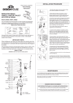
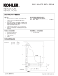
BASKET STRAINER
INSTALLATION INSTRUCTIONS
1. Remove all components from Strainer Body (1).
8
2. Apply a generous amount of plumber's putty to
underside of Strainer Flange. Insert Strainer
Body (1) through drain hole in sink.
1
Putty
3. Hold Strainer Body (1) firmly in place while installing
under the sink the Rubber Washer (2), Friction
Washer (3).
2
3
4. Hold Strainer Body (1) from rotating and thread LockNut (4) onto Strainer Body (1) using a basin wrench.
Tighten securely.
4
5. Insert Flanged Tailpiece Washer (5) into Tailpiece (6)
(not Supplied) and install Slip nut (7) with boss facing
upward, tighten firmly with wrench.
5
6
(Not
Supplied)
6. Remove excess putty from around Strainer Flange.
7. Drop in Strainer Basket (8).
7
AIR GAP
INSTALLATION
INSTRUCTIONS
(F/L)
IMPOR TANT
CAP
Air gap to be installed that the flood level mark
(F/L) shall be at or above the flood level of the
sink or other receptacle which may be connected
to the sanitary drain into which the air gap
discharges.
RIBBED
NUT
SEAL
WA S H E R
1 . R e m o v e C A P a n d R I B B E D N U T.
NUT
AIR
GAP
"Y"
FITTING
OR
HOSE
CLAMP
TRAP
HOSE
CLAMP
D I S H WA S H E R
OUTLET HOSE
(5/8" ID)
GARBAGE
DISPOSAL
D I S H WA S H E R
DRAIN
HOSE
(7/8" ID)
2. Inser t AIR GAP through sink
deck hole, leaving approximately
1/2"of the body threads showing
above sink deck. (Back the NUT
down if necessary).
3. Thread RIBBED NUT fully onto
B O D Y.
4 . T i g h t e n N U T f i r m l y.
5 . S n a p C A P o n t o R I B N U T,
with the slotted vents
facing the wall.
6 . C o n n e c t D I S H WA S H E R O U T L E T
HOSE (5/8" O.D.) to AIR GAP
inlet (smaller diameter leg) and
t o D I S H WA S H E R o u t l e t u s i n g
HOSE CLAMPS.
7
. . Connect
to AIR GAP
leg) and to
using hose
drain hose (7/8" I.D.)
outlet (larger dimension
"Y" fitting or Disposer
clamps.
GARBAGE DISPOSAL RIM & STOPPER
INSTALLATION INSTRUCTIONS
1. Push rim into sink drain until rim is seated flush
against sink drain.
STOPPER
2. Insert Stopper into Rim.
RIM
SINK DRAIN
DISPOSER
SOAP DISPENSER
INSTALLATION INSTRUCTIONS
PUMP
UNIT
PUMP
UNIT
1 . Either use an existing hole in the sink, lavatory or countertop or prepare one
specially. It should have diameter between 1" and 1-1/2". The maximum
thickness of the fixture should not exceed 1-1/2".
PUMP
HOLDER
WA S H E R
2. Pass the PUMP HOLDER down through the hole from above with the WASHER
immediately above the fixture. From below install the WASHER onto the PUMP
HOLDER and screw the NUT onto the PUMP HOLDER.
3. Screw the BOTTLE onto the lower end of the PUMP HOLDER.
WA S H E R
NUT
4. The PUMP UNIT will already be assembled within the HEAD. Push the TUBE
into the lower end of the PUMP.
5. Fill the BOTTLE through the top of the PUMP HOLDER. The BOTTLE holds
15 Fl. oz. and should not be over filled. Then place the assembled HEAD, PUMP
UNIT and TUBE into the PUMP HOLDER.
BOTTLE