1
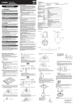
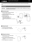
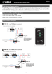
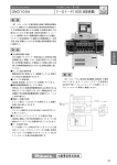
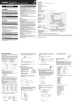
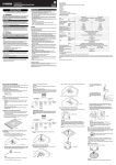
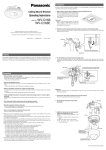
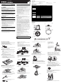
EN
Ceiling Speaker
Owner’s Manual
UNPACKING
ZE19530
Unpack the contents and confirm that all the following items are included.
English
• Speaker × 2
• Screw × 4
• Grille × 2
• Cutout Template × 1
• O-ring × 2
• Owner’s Manual (this manual)
• Tile Rail × 4
* Speaker cable and safety wire are not included.
Handling caution
PRECAUTIONS
PLEASE READ CAREFULLY BEFORE PROCEEDING
* Please keep this manual in a safe place for future reference.
WARNING
Always follow the basic precautions listed below to avoid the
possibility of serious injury or even death from electrical shock, shortcircuiting, damages, fire or other hazards. These precautions include,
but are not limited to, the following:
Do not open
• This device contains no user-serviceable parts. Do not open the device
or attempt to disassemble the internal parts or modify them in any way. If
it should appear to be malfunctioning, discontinue use immediately and
have it inspected by qualified Yamaha service personnel.
Water warning
• Do not expose the device to rain, use it near water or in damp or wet
conditions, or place on it any containers (such as vases, bottles or
glasses) containing liquids which might spill into any openings. If any
liquid such as water seeps into the device, have the device inspected by
qualified Yamaha service personnel.
SPECIFICATIONS
• Do not insert your fingers or hands in any gaps or openings on the device
(ports).
• Avoid inserting or dropping foreign objects (paper, plastic, metal, etc.)
into any gaps or openings on the device (ports). If this happens, have the
device inspected by qualified Yamaha service personnel.
• Do not operate the device if the sound is distorting. Prolonged use in this
condition could cause overheating and result in fire.
• When choosing a power amplifier for use with this device, make sure that
the output power of the amplifier is lower than the power capacity of this
device (see SPECIFICATIONS).
Even if the output power of the amplifier is lower than the power capacity
of this device (program), use of excessive input signals resulting in
clipping may cause damage to the device.
Malfunction or fire may occur especially when the following sounds or
noises are generated:
- feedback, when using a microphone
- continuous and extreme volume sound from a musical instrument
- extreme continuous distorted sound
- noise caused by plugging/unplugging the cable while the amplifier is
turned on
Type
Component
Coverage Angle (500 Hz – 4 kHz on average)
Nominal Impedance
Power Rating
NOISE
(IEC, 100h) *1
PGM
MAX
Sensitivity (1W, 1m) *2
Maximum SPL (Calculated, 1m) *3
Frequency Range (-10 dB) *2
Connector
Transformer Taps
Overload Protection
Magnetically Shielded
Enclosure
Grille
NOTICE
To avoid the possibility of malfunction/damage to the product, damage to
data, or damage to other property, follow the notices below.
CAUTION
Always follow the basic precautions listed below to avoid the
possibility of physical injury to you or others, or damage to the device
or other property. These precautions include, but are not limited to,
the following:
Location
• Do not place the device in an unstable position where it might
accidentally fall over.
• Do not place the device in a location where it may come into contact with
corrosive gases or salt air. Doing so may result in malfunction.
• Construction work should be carried out in accordance with constructionrelated law and always by a professional constructor. If the device
installation requires construction work, make sure to observe the
following precautions.
- Choose mounting hardware and an installation location that can
support the weight of the device.
- Avoid locations that are exposed to constant vibration.
- Use the required tools to install the device.
- Inspect the device periodically.
Connections
• Before connecting the device to a power amplifier, turn off the power for
all devices. Before turning the power on or off for all devices, set all
volume levels to minimum.
• Use only speaker cables for connecting speakers to the speaker jacks.
Use of other types of cables may result in fire.
Maintenance
• Do not wipe the outer packaging with benzine, thinner, or synthetic
detergent and do not use electrical contact cleaner. These may damage
the outer packaging and dissolve the parts.
● Handling and Maintenance
• Do not place vinyl, plastic or rubber objects on the device, since this
might discolor the panel.
• When cleaning the device, use a dry and soft cloth. Do not use paint
thinners, solvents, cleaning fluids, or chemical-impregnated wiping
cloths.
• Condensation can occur in the device due to rapid, drastic changes in
ambient temperature-when the device is moved from one location to
another, or air conditioning is turned on or off, for example. Using the
device while condensation is present can cause damage. If there is
reason to believe that condensation might have occurred, leave the
device for several hours until the condensation has completely dried out.
• Be sure to observe the amplifier’s rated load impedance (see
SPECIFICATIONS), particularly when connecting speakers in parallel.
Connecting an impedance load outside the amplifier’s rated range can
damage the amplifier.
• When connecting the speakers with high impedance, be sure that the
total rated input capacity of the speakers does not exceed the output
power of the amplifier.
• When using a high-impedance speaker connection, make sure the audio
signal is passed through an 80 Hz or above high-pass filter before being
input to the speakers.
• ABOUT THE PROTECTION CIRCUIT
This speaker system has an internal protection circuit that shuts off the
speaker unit when an excessive input signal is applied.
If the speaker unit emits no sound, reduce the volume level of the
amplifier immediately.
The sound will return automatically in several seconds.
• Do not swing the speaker by its strap.
• Do not place the speaker face down with the grille attached, as
deformation of the grille may result.
• When placing the speaker face down, always place it on a flat and
smooth surface.
• Do not touch the speaker driver unit.
70 V
100 V
Shape
Back Can Material
Baffle Material
Material
Finish
Dimensions (Speaker only)
Net Weight (Speaker only, 1 piece)
Cutout Size
Required ceiling board thickness
Conduit Tube
Packaging
Full Range with Back Can, Bass-reflex
4" (10 cm) Full Range
130° conical
8Ω
30 W
60 W
120 W
87 dB SPL
108 dB SPL
80 Hz – 20 kHz
Euroblock (4 pin) × 1 (input: +/-, loop-thru: +/-)
Max. wire size 12 AWG (2.5 mm2)
30 W, 15 W, 7.5 W, 3.8 W
30 W, 15 W, 7.5 W
PolySwitch
No
Back Can
Steel 1mm, Black
HIPS
Powder coated perforated steel (t=0.6 mm)
Trim Ring: ABS
Aperture ratio: 51%
VXC4 : Black painting (approximate value: Munsell N3)
VXC4W : White painting (approximate value: Munsell 9.3)
Ø225 × 194H mm (Ø8 7/8" × 7 5/8"H)
2.6 kg (5.7 lbs)
Ø186 mm (Ø7 5/16")
1 mm – 35 mm
Up to 1/2"
Packaged in pair
*1: IEC shaped pink noise with 6 dB crest factor.
*2: Half-space (2π)
*3: Calculated based on power rating and sensitivity, exclusive of power compression.
DIMENSIONS
Unit: mm
VXC4/VXC4W
O-ring
243
164
85
Ø243
Ø183
● About This Manual
The illustrations as shown in this manual are for instructional purposes only,
and may appear somewhat different from those on your device.
Yamaha cannot be held responsible for damage caused by improper use
or modifications to the device.
Tile Rail
608
32
28
38
644
INSTALLING THE SPEAKERS
There are two acceptable wiring methods.
Install the speakers onto the ceiling with the supplied hardware. Ensure that
the strength of the ceiling rail is sufficiently strong.
CAUTION
When connecting with low impedance, take note of the combined
resistance.
Pre-installation (Preparation of the Cable)
Use stranded wire for cables attached to the Euroblock connector. Strip
their insulation as shown in the figure and connect them.
About 7 mm (0.3 in.)
7 Hold the cable in the strain relief clamp, then tighten screws A and B.
Using Loop-Through Terminals
For this method, cables are connected from terminals 1 and 4 to the
subsequent speaker. If the Euroblock connector is disconnected from
a speaker, all subsequent speakers will not work. This can be useful
to identify which speaker has a problem.
NOTE
Do not plate stranded wires by solder. Doing so will cause the wire to break.
1 CUT OUT A HOLE IN THE CEILING
1 Put the supplied cutout template to the ceiling and draw a circle by
tracing it.
Make sure to use the cutout template so that hole is the correct
diameter.
8 Close the terminal cover and tighten the screw.
From amplifier or
previous speakers
NOTE
If you use a circular cutter, set the diameter with the cutout template.
2 Cut the hole by tracing the circle.
Be careful to prevent chips or powder entering your eyes while
cutting the hole.
To
subsequent
speakers
Euroblock
connector
Screw
3 Turn the screwdriver a half turn counterclockwise to loosen the
attachment screw. This makes the clamp easier to align in the
channel.
Power
amplifier
4 FIX THE SPEAKERS ONTO THE CEILING
2 INSTALL THE TILE RAILS AND O-RING
2 Insert the folded O-ring through the cut hole and open it in the ceiling.
To release the speaker from the
O-ring, press the Anti-Drop tabs.
These are located above the U
mark near the edge of the
cabinet’s face.
To subsequent
speakers
Speaker
1 Insert the two tile rails through the cut hole and place them on the
ceiling surface within your reach. Be sure that each tile rails are
oriented as shown below.
When all the Anti-Drop tabs
cross over the O-ring, the
speaker is held temporarily. You
can release your hands from the
speaker.
Paralleling Input Terminals
For this method, cables are connected to terminals 2 and 3 of each
speaker. Since the cables are connected via Euroblock connectors,
subsequent speakers can work even if a problem occurs with a
speaker.
1 Attach the safety wire to the safety wire ring, and connect the wire to
an independent support point, such as a joist.
4 Turn the screwdriver clockwise to tighten the attachment screw.
The first turn of the attachment screw aligns the clamp with the
channel. Further turns move the clamp down the channel to pull the
speaker up into the ceiling.
Safety wire ring
3 Secure the O-ring and tile rails with supplied two screws through
either slot of both O-ring brackets.
Clamp
From amplifier or
previous speakers
To subsequent
speakers
To
subsequent
speakers
Euroblock
connector
2 Push up the speaker slowly into the ceiling, taking care not to trap the
cable.
Power
amplifier
3 CONNECT THE WIRING TO THE CONNECTOR AND FIX
THE CABLE
1 Pull the wiring from the amplifier through the cut hole.
CAUTION
Always take measures to prevent the speaker falling down.
If the safety wire is too short, prepare another wire appropriate for the
speaker weight and installation conditions. If the wire is too long,
should the speaker fall, the wire may break as a result of too much
strain.
CAUTION
• Do not over-tighten the attachment screw. Otherwise, the
attachment screw and clamp will break.
• Do not turn any screws that do not have a guide sleeve in the screw
hole. Otherwise, the speaker may fall or malfunction.
5 SET THE LINE VOLTAGE/IMPEDANCE AND POWER
Speaker
Select the line voltage/impedance (100V/70V/8Ω) and power tap for 100V/
70V line distributed system, by rotating the tap selector switch on the front
side of the speaker with a flat-blade screwdriver.
4 Plug the connected Euroblock connector into the socket in the
speaker.
2 Loosen the screw at the right of the terminal cover to open the
terminal cover and remove the Euroblock connector.
Euroblock connector
CAUTION
The “X” position should not be selected. The 8Ω position should be selected
for 8Ω audio systems only. If the setting is incorrect, it may cause
malfunction of the speaker and amplifier.
Terminal cover
6 ATTACH THE GRILLE
5 Loosen the screw A of the strain relief clamp.
3 After loosening the terminal screws of the Euroblock connector with a
flat-blade screwdriver, insert the cable into each terminal and tighten
the screws. Make sure that cables cannot be pulled out.
6 Remove the screw B of the strain relief clamp.
If the cable is not to be held, remove the screw A and remove the
strain relief fitting, then proceed to step 8.
Fit the grille to the cabinet front and turn it clockwise.
Anti-Drop tab
B
Euroblock connector
A
NOTE
Use a flat-blade screwdriver with a blade less than 3 mm (0.1 in.).
Less than 3 mm (0.1 in.)
CAUTION
The grille may fall down if it is attached inadequately. Attach it firmly.
Yamaha Pro Audio global web site
http://www.yamahaproaudio.com/
Yamaha Manual Library
http://www.yamaha.co.jp/manual/
C.S.G. Pro Audio Division
© 2012 Yamaha Corporation
308YKCR*.*-**C0
Printed in Indonesia