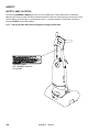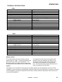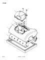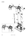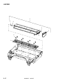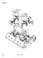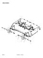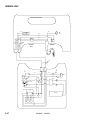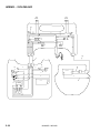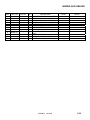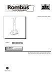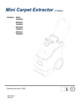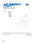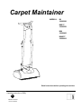
1
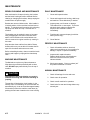
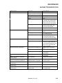
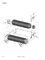
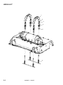
Carpet Maintainer
MODELS:
IM
10066360
IMIE17
10066550
IMX
10066400
IMXIE17
10066410
Read instructions before operating the machine.
Operating Instructions (ENG)
L
86269870 08/20/08
PRV NO. 980305
DATA LOG/OVERVIEW
MODEL _______________________________________
DATE OF PURCHASE __________________________
SERIAL NUMBER ______________________________
SALES REPRESENTATIVE # _____________________
YOUR DEALER
NAME: __________________________________________________________________________________________________
ADDRESS:_______________________________________________________________________________________________
PHONE NUMBER: _______________________________________________________________________________________
OVERVIEW
The Carpet Maintainer is designed to maintain carpet using the Quick Dry Carpet Care
System. The machine has two counter rotating brushes that scrub chemical into the
carpet. The chemicals, iCapsol or Prochem ProCaps, encapsulates the dirt, allowing both
to be vacuumed up once the chemical has dried. The brushes also raise the pile of the
carpet. The Deluxe models have a solution tank and pump powered spraying system,
which applies the chemical to the carpet as the machine is used.
2
86269870 04/02/07
TABLE OF CONTENTS
Data Log/Overview. ...................................2
Table of Contents.......................................3
HOW TO USE THIS MANUAL
How to use this Manual..............................1-1
SAFETY
Important Safety Instructions .....................2-1
Hazard Intensity Level. ..............................2-2
Grounding Instructions...............................2-3
Safety Label Location ................................2-4
OPERATIONS
Technical Specifications. ...........................3-1
How the Machine Works. ...........................3-2
Machine Operation.....................................3-3
Pre-run Inspection. .............................3-3
Starting Machine.................................3-3
Shut-down and Storage......................3-4
Components...............................................3-5
PARTS LIST
Brush ........................................................ 5-1
Brush Lift ................................................... 5-3
Decal.......................................................... 5-5
Electrical-120V........................................... 5-7
Electrical-230V........................................... 5-9
Frame ........................................................ 5-11
Frame-Deluxe ............................................ 5-13
Handle ....................................................... 5-15
Hopper ....................................................... 5-17
Motor.......................................................... 5-19
Rear Wheel................................................ 5-21
Solution Tank-Deluxe ................................ 5-23
Wiring-120V ............................................... 5-25
Wiring-230V ............................................... 5-27
Suggested Spare Parts.............................. 5-29
Warranty .................................................... 5-30
MAINTENANCE
Brush Cleaning and Maintenance..............4-1
Machine Maintenance................................4-1
Daily Maintenance. .............................4-1
Periodic Maintenance. ........................4-1
Annual Maintenance...........................4-1
Machine Troubleshooting...........................4-2
86269870
07/11/07
3
HOW TO USE THIS MANUAL
The PARTS LIST section contains assembled parts
illustrations and corresponding parts list. The parts
lists include a number of columns of information:
This manual contains the following sections:
-
HOW TO USE THIS MANUAL
SAFETY
OPERATIONS
MAINTENANCE
PARTS LIST
-
The HOW TO USE THIS MANUAL section will tell
you how to find important information for ordering
correct repair parts.
-
Parts may be ordered from authorized dealers.
When placing an order for parts, the machine model
and machine serial number are important. Refer to
the MACHINE DATA box which is filled out during
the installation of your machine. The MACHINE
DATA box is located on the inside of the front cover
of this manual.
-
-
MODEL _____________________________
-
REF – column refers to the reference
number on the parts illustration.
PART NO. – column lists the part
number for the part.
QTY – column lists the quantity of the
part used in that area of the machine.
DESCRIPTION – column is a brief
description of the part.
SERIAL NO. FROM – column indicates
the first machine the part number is
applicable to. When the machine design
has changed, this column will indicate
serial number of applicable machine.
The main illustration shows the most
current design of the machine. The
boxed illustrations show older designs. If
column has an asterisk (*), call
manufacturer for serial number.
NOTES – column for information not
noted by the other columns.
DATE OF PURCHASE ___________________
NOTE: If a service or option kit is installed on your
machine, be sure to keep the KIT INSTRUCTIONS
which came with the kit. It contains replacement
parts numbers needed for ordering future parts.
SERIAL NUMBER _____________________
SALES REPRESENTATIVE # _____________
NOTE: The 98# on the lower left corner of the front
cover is the part number for this manual.
The model and serial number of your machine is on
the operator’s left hand side, side panel of base.
The SAFETY section contains important information
regarding hazard or unsafe practices of the
machine. Levels of hazards is identified that could
result in product or personal injury, or severe injury
resulting in death.
The OPERATIONS section is to familiarize the
operator with the operation and function of the
machine.
The MAINTENANCE section contains preventive
maintenance to keep the machine and its
components in good working condition.
1-1
86269870
04/02/07
SAFETY
IMPORTANT SAFETY INSTRUCTIONS
When using an electrical appliance, basic precaution
must always be followed, including the following:
READ ALL INSTRUCTIONS BEFORE USING THIS MACHINE.
! WARNING:
To reduce the risk of fire, electric shock, or injury:
Connect to a properly grounded outlet. See Grounding Instructions.
Do not leave the machine unattended. Unplug machine from outlet when not in use and before
maintenance or service.
Do not allow machine to be used as a toy. Close attention is necessary when used by or near
children.
Use only as described in this manual. Use only manufacturer’s recommended components and
attachments.
Do not use damaged electrical cord or plug. Follow all instructions in this manual concerning grounding
the machine. If the machine is not working properly, has been dropped, damaged, left outdoors, or
dropped into water, return it to an authorized service center.
Do not pull or carry machine by electrical cord, use as a handle, close a door on cord, or pull cord
around sharp edges or corners.
Do not run machine over cord or allow the rotating brushes to come in contact with the cord. Keep cord
away from heated surfaces.
Do not unplug machine by pulling on cord. To unplug, grasp the electrical plug, not the electrical cord.
Do not handle the electrical plug or machine with wet hands.
Do not operate the machine with any openings blocked. Keep openings free of debris that may reduce
airflow.
Machine is designed for indoor use only and must not be operated or stored outdoors in wet
conditions.
Turn off all controls before unplugging.
This machine is suitable for commercial use, including hotels, schools, hospitals, factories,
shops and offices for more than normal housekeeping purposes.
Maintenance and repairs must be done by qualified personnel.
Machine can cause a fire when operating near flammable vapors or materials. Do not operate this
machine near flammable fluids, dust or vapors.
SAVE THESE INSTRUCTIONS
86269870
04/02/07
2-1
SAFETY
HAZARD INTENSITY LEVEL
The following symbols are used throughout this guide as indicated in their descriptions:
There are three levels of hazard intensity identified by signal words -WARNING and CAUTION and FOR
SAFETY. The level of hazard intensity is determined by the following definitions:
WARNING - Hazards or unsafe practices which could result in severe personal injury or death.
! WARNING
CAUTION - Hazards or unsafe practices which could result in minor personal injury or product or property
damage.
! CAUTION
FOR SAFETY: To Identify actions which must be followed for safe operation of equipment.
Report machine damage or faulty operation immediately. Do not use the machine if it is not in proper
operating condition. Following is information that signals some potentially dangerous conditions to the
operator or the equipment. Read this information carefully. Know when these conditions can exist. Locate
all safety devices on the machine. Please take the necessary steps to train the machine operating
personnel.
FOR SAFETY:
DO NOT OPERATE MACHINE:
Unless Trained and Authorized.
Unless Operation Guide is Read and understood.
In Flammable or Explosive areas.
In areas with possible falling objects.
WHEN SERVICING MACHINE:
Avoid moving parts. Do not wear loose clothing; jackets, shirts, or sleeves when working on the
machine. Use approved replacement parts.
2-2
86269870
04/02/07
SAFETY
THIS PRODUCT IS FOR COMMERCIAL USE
ONLY.
ELECTRICAL
In the USA, this machine operates on a standard 15
amp 120V, 60 hz, A.C. power circuit. The amp,
hertz, and voltage are listed on the data label found
on each machine. Using voltages above or below
those indicated on the data label will cause serious
damage to the motors.
EXTENSION CORDS
If an extension cord is used, the wire size must be at
least one size larger than the power cord on the
machine, and must be limited to 50 feet (15.5m) in
length.
GROUNDING INSTRUCTIONS –
120V ONLY
This appliance must be grounded. If it should
malfunction or break down, grounding provides a
path of least resistance for electric current to reduce
the risk of electric shock. This appliance is equipped
with a cord having an equipment-grounding
conductor and grounding plug. The plug must be
inserted into an appropriate outlet that is properly
installed and grounded in accordance with all local
codes and ordinances.
! WARNING
Improper connection of the equipmentgrounding conductor can result in a risk of
electric shock. Check with a qualified electrician
or service person if you are in doubt as to
whether the outlet is properly grounded. Do not
modify the plug provided with the appliance - if it
will not fit the outlet, have a proper outlet
installed by a qualified electrician.
This appliance is for use on a nominal 120-volt
circuit, and has a grounded plug that looks like the
plug in “Fig. A”. A temporary adaptor that looks like
the adaptor in “Fig. C” may be used to connect this
plug to a 2-pole receptacle as shown in “Fig. B”, if a
properly grounded outlet is not available. The
temporary adaptor should be used only until a
properly grounded outlet (Fig. A) can be installed by
a qualified electrician. The green colored rigid ear,
lug, or the like extending from the adaptor must be
connected to a permanent ground such as a
properly grounded outlet box cover. Whenever the
adaptor is used, it must be held in place by a metal
screw.
86269870
04/02/07
2-3
SAFETY
SAFETY LABEL LOCATION
The following WARNING LABEL(S) are found on your cleaning unit. These labels point out important
Warnings and Cautions which should be followed at all times. Failure to follow warnings and cautions could
result in fatality, personal injury to yourself and/or others, or property damage. Follow these instructions
carefully! DO NOT remove these labels.
NOTE: If at any time the labels become illegible, promptly replace them.
WARNING LABEL
PART NUMBER 86220140
PRV 500895
2-4
86269870
04/02/07
OPERATIONS
TECHNICAL SPECIFICATIONS
120V
ITEM
Electrical
Nominal Power
Rated Amperage
Brush Width
Brush RPM
Wheels
Dimensions - Weight
- Weight - Deluxe
Dimensions – Height with handle
Dimensions – Depth
Power Cord
Solution Tank Volume - Deluxe
Pump Pressure - Deluxe
Solution Flow - Deluxe
Spray Jet Size - Deluxe
DIMENSION/CAPACITY
120V
0.5 HP
7 Amps
17 – 16.5” (430 - 420 mm)
470 RPM
3 inches (75 mm) non-marking grey
48 lbs. (22 kg)
56 lbs. (25 kg)
45.5” (1.16 m)
16 inches (0.4 m)
40 feet (12.2 m)
2 gallon
50 psi
0.1 gpm
.010
230V
ITEM
Electrical
Nominal Power
Rated Amperage
Brush Width
Brush RPM
Wheels
Dimensions - Weight
- Weight - Deluxe
Dimensions – Height - with handle
Dimensions – Depth
Power Cord
Solution Tank Volume - Deluxe
Pump Pressure - Deluxe
Solution Flow - Deluxe
Spray Jet Size - Deluxe
DIMENSION/CAPACITY
230V
0.5 HP
4 Amps
17 – 16.5” (430 - 420 mm)
470 RPM
3 inches (75 mm) non-marking grey
48 lbs. (22 kg)
56 lbs. (25 kg)
45.5” (1.16 m)
16 inches (0.4 m)
40 feet (12.2 m)
2 gallon
50 psi
0.1 gpm
.010
SPECIAL NOTES:
The sound pressure level at the operator’s ear was
measured to be 67.7dBA . This was a nearfield, broadband measurement taken on a carpeted floor. This
appliance contains no possible source of impact noise.
The instantaneous sound pressure level is below 63 Pa.
NOTES:
The weighted root mean square acceleration at the
operator’s arms was measured to be below 2.5m/s2 .
This was a tri-axial, third-octave-band measurement
made during normal operation on a composite tile
floor. The measurement and related calculations were
made in accordance with ISO 5349-1.
This appliance is not intended for use by persons (including children) with reduced physical, sensory or mental
capabilities, or lack of experience and knowledge, unless they have been given supervision or instruction concerning
use of the appliance by a person responsible for their safety. Children should be supervised to ensure that they do
not play with the appliance.
86269870
04/14/08
3-1
OPERATIONS
HOW THE MACHINES WORK
The Carpet Maintainer is designed to maintain your
carpet using the Quick Dry Carpet Care System. By
using the Carpet Maintainer in conjunction with
iCapsol or Prochem ProCaps chemical solution, you
can perform a regular light cleaning and grooming of
your carpet very quickly, and have the carpet dry
and ready for traffic within 20 minutes.
The handle movement flexibility allows the machine
to clean under low furniture. There is a hand
operated on/off switch and auto-handle lock keeping
the handle in an upright position. This unit is
equipped with a safety feature that when unplugged
from the wall or the handle dropped, will
automatically reset to the off position .
The debris tray is used to catch unwanted carpet
debris and should be cleaned regularly and prior to
transporting.
This appliance conforms with international and
national safety directives: EN55014-2, EN5504-1,
EN61000-3-2/3-3, EN60335-1/2-10/2-69/2-67. IEC
60335-1/2/10/2-67/2-69. LVD 73/23/EEC.
DELUXE
This unit is equipped with an onboard spray pump
and solution tank. By using the onboard spraying
system a light treatment of chemical can be applied
to the carpet and brushed in during a single pass of
the machine.
QUICK DRY CARPET CARE SYSTEM
INSTRUCTIONS
Test for colorfastness in an inconspicuous area
before use.
1.
4. No dwell time is required. Do not allow
chemical to dry before brushing.
5. Brush treated area to emulsify soils using
the Windsor iCapsol or other carpetbrushing machine.
6. Allow to dry until dry to touch (approximately
20 minutes) before opening area to traffic.
7. Vacuum carpet when fully dry to remove
encapsulated soil.
Tips: Pre-treat carpet spots with iCapsol Interim
cleaning solution. Work on a manageable area
and do not allow cleaning solution to dry on
carpet before brushing.
DELUXE
The Deluxe is provided with a removable
solution tank. To remove tank for filling and
cleaning, press the gray release button on the
blue coupler located at the top of the tank. Next
remove upper straps from mounting pegs. The
tank will now freely separate from the machine
base. After filling tank remount to machine by
reversing the process mentioned above.
The proper 1:16 dilution ratio can be achieved
by adding one pint (16 oz.) of recommended
chemical and slowly filling the tank with water (2
gallons). Adding water slowly will help prevent
foaming.
To achieve a coverage rate of 600–1000 sq. ft.
per gallon using the onboard sprayer, spray
solution only during the forward stroke of
operation. Use the backstroke to brush the
chemical into the carpet.
Vacuum carpet to remove loose soil.
2. Dilute iCapsol or Prochem ProCaps at 8oz. per
gallon of water (1:16) into the solution tank.
3. Pre-spray carpet to be cleaned at a rate of 600–
1000 sq. ft. per gallon of diluted solution. Do not
over wet.
3-2
86269870
07/11/07
OPERATIONS
MACHINE OPERATION
PRE-RUN INSPECTION
Perform a pre-run inspection to find possible
problems that could cause poor performance or
lost time from breakdown. Check the rating plate
to confirm voltage and frequency is the same as
the power supply. NOTE: A 10% variation in
voltage is acceptable.
STARTING MACHINE – DELUXE
STARTING MACHINE
1. Connect the machine to a power supply.
NOTE: Perform pre-run machine check before
operating machine.
FOR SAFETY: Before starting machine, make
sure that all covers are in place and secured
properly.
NOTE: Perform pre-run machine check before
operating machine.
FOR SAFETY: Before starting machine, make
sure that all covers are in place and secured
properly.
2. Release the handle lock.
3. (a) Press green button to power on machine,
120V only.
(b) Set black on/off switch to “on” position,
230V only.
1. Connect the machine to a power supply.
2. Release the handle lock.
4. Press green button to start brushes.
3. (a) Press green button to power on the
machine,120V only.
(b) Set black on/off switch to “on” position,
230V only.
4. Press green button to start brushes.
After applying a light spray of diluted interim
carpet cleaner onto the carpet using a pressurized
tank sprayer, commence cleaning by pushing and
pulling the machine slowly over the wetted carpet.
Move the machine in multiple directions and
overlapping strokes.
For best results use Windsor iCapsol or Prochem
ProCaps products.
5. Press and hold blue button to spray chemical.
Once machine is plugged in spray function is
operational.
Apply a light spray of diluted interim carpet
cleaner onto the carpet using the onboard
spraying system. Spray chemical while pushing
the machine forward. Brush the chemical into the
carpet while pulling the machine slowly over the
wetted carpet. Move the machine in multiple
directions and overlapping strokes.
For best results use Windsor iCapsol or Prochem
ProCaps products.
! WARNING
Flammable materials can cause an explosion or
fire. Do not use flammable materials with this
machine.
86269870 08/20/08
3-3
OPERATIONS
TRANSPORTING A SPRAYER
SHUT-DOWN AND STORAGE
1. This machine has the capability to mount a
small pump-up sprayer.
1. Flush the spray jet and tank with hot water
(Deluxe only)
TRANSPORTING CHEMICAL - DELUXE
1. This machine has the capability to mount
chemical bottles or trigger sprayers to the
back of the solution tank.
2. After flushing, uncouple quick disconnect to
prevent water from dripping out of front jet.
3. a. Press red button to power off machine
120V only.
b. Set black on/off switch to “off” position
230V only.
! WARNING
This Machine is not intended to carry more than
30 pounds. Carrying more than 30 pounds could
cause damage to the machine.
4. Lock handle in the upright position.
5. Disconnect the power cord from the power
supply. Wind the power cord around the cable
holders on the handle.
6. Remove the brushes for cleaning. See Brush
Cleaning and Maintenance section.
7.
Clean debris tray.
The machine is now ready for storage until the
next use. Make sure to store your equipment in a
dry place to prolong the life of your machine.
Storage outdoors or unprotected could cause
damage to your machine or internal parts,
therefore voiding your warranty.
3-4
86269870
08/20/07
COMPONENTS
8
2
1A
1B
1A
1B
2
5
4
4
6
3
1A.
1B.
2.
3.
4.
3
7
iCapsol Mini
iCapsol Mini Deluxe
Stop Switch (red-120V only)
On/Off Switch (black-230 only)
Start Switch (green)
Brushes
Handle Release
5.
6.
7.
8.
86269870
Tank
Strainer
Jet
Spray Pump Switch
07/11/07
3-5
MAINTENANCE
BRUSH CLEANING AND MAINTENANCE
DAILY MAINTENANCE
After each session of carpet cleaning, the brushes
and the brush housing should be cleaned. Before
cleaning or changing the brushes, always unplug the
machine from the power supply.
1. Clean and inspect brushes.
Brushes are removed without tools. After handle is
in locked position, tilt the machine back and rest on
handle. To release brush from spring clip pull spring
clip away from brush end cap. Lift brush out of
machine.
3. Inspect power cord for wear or damage.
This cable will lie on wet carpet. To prevent
electrical shock replace cords that are
frayed or have cracked insulation
immediately.
The brushes may be soaked in warm or hot water
using mild detergent, and then rinsed with warm
water. NOTE: Brushes with crushed bristles can
often be restored to original condition by soaking in
hot water.
4. Flush the tank, pump and spray jet with hot
water (Deluxe only).
Keep brushes clean and free from debris. Rotate
brushes after every use as this will increase the life
span of the brushes and ensure even wear.
Before reinstalling brushes, clean out machine brush
housing and hopper by wiping with a clean damp
cloth.
MACHINE MAINTENANCE
The Maintainer requires very little maintenance.
Wipe down the machine periodically with a clean
cloth. DO NOT spray water directly over the top of
machine.
2. Clean and inspect brush housing, debris tray
and machine. Rinse debris tray if needed.
5. Clean Strainer.
PERIODIC MAINTENANCE
1. Check all handles, switches, electrical
cables and connections on your machine for
damage. Repair or replace immediately.
2. Inspect and/or replace brushes.
Replace brushes when main bristles are
worn to the same level as the yellow
indicator bristles.
3. Check spray pattern. Clean or replace jet if
the pattern is blocked or uneven
ANNUAL MAINTENANCE
! CAUTION
1. Check all bearings for noise and wear.
Deformation of the brush bristles can result in
unbalanced running and excessive vibrating or
jumping.
2. Check motor for operation.
3. Check overall machine for operation.
The machine is fitted with a circuit breaker. In the
unlikely event of overloading, the circuit breaker will
automatically trip. It can be reset after approximately
30 seconds (or when the machine cools down) by
pushing the set button located on the cover housing.
4-1
86269870
4. Check belts for wear and change belts every
second year.
07/11/07
MAINTENANCE
MACHINE TROUBLESHOOTING
PROBLEM
CAUSE
SOLUTION
No power to machine
Tripped electrical circuit
breaker in fuse box of building
Faulty power cord
Power switch failure or relay
failure
Tripped circuit breaker
Check building circuit breaker
Internal wiring problem
Faulty rectifier
Electrical Shock
Equipment not grounding
Receptacle not grounded
Interal electrical problem
Nuisance tripping of circuit breaker
Faulty circuit breaker
Mechanical problem
Brush not turning or scrubbing
Faulty brush motor/gear box
Belt failure
Worn brush motor brushes
Power to motor but motor does not
run
Bearing squealing or grinding in
brush housing
Machine will only run if the green (on)
switch is continuously held down
No flow or uneven flow from jet
(Deluxe only)
Weak flow from clean jet
(Deluxe only)
Pump runs but no flow from jet
(Deluxe only)
Replace power cord
Replace power switch or
relay
Reset circuit breaker. Higher
amp draw may indicate faulty
parts. Find parts not moving
freely and correct as needed.
With machine unplugged,
check for and correct, any
loose wire connections.
Replace rectifier
Follow grounding instructions,
pg 2-3
Have an electrician inspect
the building’s wiring
Check for any loose wire
connections, replace any
items that are short circuiting
Replace circuit breaker
Test circuit breaker for
continuity. Higher amp draw
may indicate faulty parts. Find
parts not moving freely and
repair or replace.
Replace brush motor/gear
box
Replace belts
Worn bearings
Replace brushes, check
commutator
Replace brushes, check
commutator
Replace worn bearing
Defective red (off) switch.
Sends constant “off” signal.
Clogged jet
Replace or reconnect wire to
red (off) switch
Clean or replace jet
Clogged strainer
Clean strainer
Disconnect coupling at
solution tank
Attach the quick coupling to
the solution tank
Worn brush motor brushes
86269870 07/11/07
4-2
BRUSH
3
6
5
4
3
7
2
1
8
5-1
86269870
01/02/08
BRUSH
REF
PART NO.
PRV NO.
QTY
DESCRIPTION
1
2
3
4
5
6
7
8
86217340
86172630
86172870
86224670
86214850
86217330
86216070
86172840
270130
57314
70898
730396
12544
270129
12535
70886
1
2
6
2
2
1
2
6
COVER, BELT, RIGHT
NUT, M4, LK, SST
SCR, M4X14, PHMS, DIN7985 SST
SPRING, BRUSH CLIP
ASSY, BRUSH & HUB
COVER, BELT, LEFT
ASSY, BRUSH DRIVE
SCR, M5X10, PHS, FHD, SST
86269870
01/02/08
SERIAL NO.
FROM
NOTES:
5-2
BRUSH LIFT
1
2
3
4
5
6
5-3
86269870
04/02/07
BRUSH LIFT
REF
PART NO.
PRV NO.
QTY
DESCRIPTION
1
2
3
4
5
6
86215580
86172700
86215750
86224760
86215740
86223620
141042
67606
09156
73997
09155
67605
2
4
4
4
4
2
BRACKET, CROSSOVER PUSH
RING, E-TYPE, 5MM ID, DIN6799
BRG, FLNG, 6MM IDX7MM LONG
SPRING, COM, 18.28 OD X 25L
BRG, FLNG, 6MM IDX24MM LONG
ROD, LIFTING
86269870 04/02/07
SERIAL NO.
FROM
NOTES:
5-4
DECAL
1
2A
2B
5-5
86269870
01/02/08
DECAL
REF
PART NO.
PRV NO.
QTY
1
2A
2B
86221620
86244630
86244920
501260
501190
501247
1
1
1
DESCRIPTION
LABEL, CHEMICAL INSTR.
LABEL, MAIN, ICAPSOL MINI
LABEL, PROCAP PROCHEM
86269870
01/02/08
SERIAL NO.
FROM
NOTES:
DELUXE ONLY
WINDSOR ONLY
PROCHEM ONLY
5-6
ELECTRICAL-120V
DELUXE ONLY
27
28
26
31
29
27
6 7
30
8
2
13 12
16
1
8
7
19
17
18
15
23 23
15
22
6
20
20
14
26
10
DELUXE ONLY
11
9
5
25
21
3
8
5
4
5-7
86269870
08/20/08
ELECTRICAL-120V
SERIAL NO.
FROM
REF
PART NO.
PRV NO.
QTY
DESCRIPTION
1
2
3
4
5
6
7
8
9
10
11
12
13
14
15
16
17
18
19
20
21
22
23
24
25
26
86002010
86217120
86214770
86214780
86225070
86198450
86225320
86173100
86291470
86291490
86291880
86216800
86277600
86215670
86172880
86173200
86225850
86223400
86223390
86173210
86291860
86222670
86216740
OPEN
86013570
86299320
14942
23729
38370
38371
38372
20005
78601
70935
20110
70882
140839
70901
70950
87517
67516
67488
70951
05248
20040
-
1
1
1
1
2
2
1
4
1
1
2
1
1
1
5
1
2
1
1
4
1
1
2
2
2
BOOT, 3/8 CIRCUIT BREAKER
CORD SET, 18/3 X 40FT SJT
ASM RED BUTTON W/BEZEL
ASM GREEN BUTTON W/BEZEL
SWITCH, ITW, MICRO
CLAMP, 5/16 NYLON
TIE, CABLE NYLON
SCR, M3X6, BSHCS, SST
BRKT, MTR BRKT, SWITCH, CVR
COVER, SWITCH, BRKT
SCR, M3X12, BSHCS, SST
CLIP, WIRE
SCR, M4X20, PPHMS, SST
BREAKER, 8A VDE CIRCUIT
SCR, M4X6, BSHCS, SST
SCR, M4X16, BSHCS, SST
WASHER, M3, FL, ISO7089, SST
RELAY, 15A 120VAC MINI
RECTIFIER, 50A 600V BRIDGE
SCR, M5X10, BSHCS, SST
SWITCH, 125VAC SP NC ROLLER
PLATE, BASE, ELECTRICAL MTG
CLAMP, 17,7 NYLON
SWITCH, PUSHBUTTON, BL, DLX
LABEL, GROUND SYMBOL
27
86313930
-
4
SWITCH, W/COUPLER, N.C.
*(1)
28
29
30
86295190
86295150
86295180
-
2
1
1
ASM, BUTTON, BLUE, W/BEZEL
ASM, BUTTON, RED, W/BEZEL
ASM, BUTTON, GREEN, W/BEZEL
*(1)
*(1)
*(1)
31
86313930
-
4
SWITCH, W/COUPLER, N.O.
*(1)
NOTES:
DELUXE ONLY
BASIC (QTY 1)
DELUXE (QTY 2)
DELUXE ONLY
BASIC (QTY 1)
DELUXE (QTY 1)
*SEE SERIAL NUMBER PAGE
**CALL MANUFACTURER FOR SERIAL NUMBER
86269870 08/20/08
5-8
ELECTRICAL-230V
DELUXE ONLY
3
30
19 31
28
4
3
1
2
5
6
14 13
7
23
29
12
24
25
22
15
4
8
8
4
16
18
5
17
31
27
20
21
33
32
26
5-9
86269870
08/20/08
ELECTRICAL-230V
REF
PART NO.
PRV NO.
QTY
DESCRIPTION
1
2
86299810
86295180
-
1
1
SWITCH, BLACK, ROCKER, DPST
ASM, BUTTON, GREEN, W/BEZEL
3
86313930
-
3
SWITCH, W/COUPLER, N.C.
4
5
6
7
8
9
10
11
12
13
14
15
16
17
18
19
20
21
22
23
24
25
86172880
86198450
86217200
86002010
86216740
86215910
86225080
86173110
86173100
86216800
86277600
OPEN
86215710
86173210
86222670
86225320
86291490
86291880
86223420
86173200
86223390
86225850
70901
20005
23738
14942
20040
140972
72152
70936
70935
20110
70882
141046
70951
05248
78601
67622
70950
67488
87517
5
2
1
1
2
1
1
2
3
1
1
1
4
1
4
1
2
1
1
1
2
26
86291860
-
1
27
28
29
30
31
32
33
86299320
86299830
86264940
86295190
86299320
86173100
86291470
27051
70935
-
1
1
1
2
2
2
1
SCR, M4X6, BSHCS, SST
CLAMP, 5/16 NYLON
CORD SET, 18/3 X 40FT SJT
BOOT, 3/8 CIRCUIT BREAKER
CLAMP, 17,7 NYLON
BRKT, MTR BRKT, SWITCH
SWITCH, 125VAC SP NC ROLLER
SCR, M3X16, BSHCS, SST
SCR, M3X6, BSHCS, SST
CLIP, WIRE
SCR, M4X20, PPHMS, SST
BREAKER, 5A VDE CIRCUIT
SCR, M5X10, BSHCS, SST
PLATE, BASE, ELECTRICAL MTG
TIE, CABLE NYLON
COVER, SWITCH, BRKT
SCR, M3X12, BSHCS, ISO7380, SS
RELAY, 10A 230V MINI SPDT
SCR, M416, BSHCS, SST
RECTIFIER, 50A 600V BRIDGE
WASHER, M3, FL, ISO7089, SST
SWITCH, 125VAC SP NC NOROLLER
LABEL, GROUND SYMBOL
COVER, SWITCH, PVC
CABLE TIE, 11.38” UL/CSA
ASM, BUTTON, BLUE, W/BEZEL
LABEL, GROUND SYMBOL
SCR, M3X6, BSHCS, ISO7380, SST
BRKT, MTR BRKT, SWITCH
SERIAL NO.
FROM
*(1)
NOTES:
BASIC (QTY 1)
DELUXE (QTY 3)
DELUXE ONLY
*SEE SERIAL NUMBER PAGE
**CALL MANUFACTURER FOR SERIAL NUMBER
86269870
08/20/08
5-10
FRAME
7
6
5
4
3
2
1
5-11
86269870
04/14/08
FRAME
REF
PART NO.
PRV NO.
QTY
1
2
3
4
86225340
86217930
86214820
86277600
78952
34450
05262
70882
1
1
1
1
5
86222360
58009
1
6
7
86214830
86173050
05263
70920
1
3
DESCRIPTION
SERIAL NO.
FROM
NOTES:
TRAY, IRENEW MINI
FRAME, 3.5”, SINGLE MOTOR
ASSY, COVER, INSULATION
SCR, M4X20, PPHMS, SST
NUT, M4X0.7, U-CLAMP, 3MM
PANEL
ASSY, DOME, INSULATION
SCR, M4X40, PPHMS, SST
86269870
04/14/08
5-12
FRAME – DELUXE
1
14
13
12
2
10
11
9
3
8
7
4
6
5
5-13
86269870
08/20/08
FRAME-DELUXE
REF
PART NO.
PRV NO.
QTY
DESCRIPTION
1
2
3
4
5
6
7
8
9
10
11
12
86173050
86173040
86011610
86217930
86225340
86012550
86004570
86012440
86197520
86233090
86290790
86277600
70920
70919
34450
78952
44067
40011
20016
70882
3
3
1
1
1
1
1
1
1
1
1
1
13
86222360
58009
1
14
86214830
05263
1
SCR, M4 X 40 PPHMS, SS
SCR, M4 X 10 SHCSB BUTHD
ASSY, COVER, INSULATION, DLX
FRAME, 3.5, SINGLE MOTOR
TRAY, IRENEW MINI
JET, PROMAX, 11001
JET BODY, MINI PROMAX BODY
MANIFOLD, SPRAYER, DLX, IMX
HOSEBARB, 1/8MPT X 1/4 DL
CLAMP, 1/4 ID HOSE
SCR, M6 X 8, CP, BLK
SCR, M4 X 20, PHMS, SST
NUT, M4 X 0.7, U-CLAMP, 3MM
PANEL
ASSY, DOME, INSULATION
86269870
08/20/08
SERIAL NO.
FROM
NOTES:
5-14
HANDLE
26
23A
23B
3
19
18
17 16
25A
25B
4
3
15A
15B
24
21
14
5
3
13
6A
6B
22
1
12
2
8A
8B
11
9
10
20
7
5-15
86269870
08/20/08
HANDLE
SERIAL
NO.
REF
PART NO.
PRV NO.
QTY
DESCRIPTION
1
2
3
4
5
6A
6B
7
8A
8B
9
10
11
12
13
14
15A
15B
16
17
18
19
20
21
22
86011380
86059580
86277600
86217230
86217220
86218680
86218510
86173070
86013820
86222650
86173180
86221800
86172640
86221810
86224970
86223640
86218690
86218520
86224680
86223450
86012940
86172820
86216890
86172870
86294260
38324
70882
38326
38325
38357
38321
70922
38354
70948
279992
57507
279993
730382
38332
38358
38322
730414
67620
70883
38327
70898
-
1
1
9
1
2
1
1
4
1
1
2
1
2
1
1
4
1
1
1
1
1
2
1
2
4
GRIP, HANDLE
CONSOLE, BOTTOM
SCR, M4X20, PPHMS, SST
CORD HOOK, UPPER
CORD HOOK, LOWER
HANDLE, EXTRUSION, LEFT
HANDLE, EXTRUSION, LEFT
SCR, M5X12, CSK.OVL,ISO 7047,SS
PIVOT CASTING, DLX
PIVOT CASTING
SCR, 10M8X55, SHLD, BLK
LIFTING CAM, LEFT
NUT, M8, LK, SST
LIFTING CAM, RIGHT
STRAP, SPRAYER HOLD DOWN
RUBBER STRAP HOOK
HANDLE, EXTRUSION, RIGHT
HANDLE, EXTRUSION, RIGHT
SPRING, COMP, 11.56D X 19.05L
RETAINER, SPRING, CORD HOOK
SCR, KA40X35, PT OVAL, WN1412, PL
SCR, M5X20, PPHMS, SST
CONSOLE, TOP
SCR, M4X14, PPHMS, ISO7045, SST
SCR, M5X12, W/LOCTITE
23A
86305580
-
1
CONSOLE, BOTTOM, DLX
*
23B
86293330
-
1
CONSOLE, BOTTOM
*
24
86308740
-
4
SCR, M5X30,CSK, OVL, ISO7047,SS
*
25A
86293340
-
1
CONSOLE, TOP
*
25B
86305590
-
1
CONSOLE, TOP
*
26
86299750
-
1
GRIP, HANDLE
*
86269870
08/20/08
NOTES:
DELUXE ONLY
DELUXE ONLY
DELUXE ONLY
DELUXE 110V
& BASIC 110V
DELUXE 230V
& BASIC 230V
DELUXE 110V
& BASIC 110V
DELUXE 230V
& BASIC 230V
5-16
HOPPER
3
4
5
6
7
2
2
1
5-17
86269870
04/02/07
HOPPER
REF
PART NO.
PRV NO.
QTY
1
2
3
4
5
6
7
86214790
86173040
86214800
86173080
86216310
86172630
86217450
41584
70919
41585
70933
140977
57314
270709
1
10
1
1
1
1
1
DESCRIPTION
SERIAL NO.
FROM
NOTES:
ASM, GUIDE, HOPPER
SCR, M4X10, BSHCS, SST
ASM, HOPPER FRAME & PLATE
SCR, 4.2 X 9.5, TAP, ZN
BUMPER, STOP, HOPPER
NUT, M4, LK, SST
COVER, FRONT, HOPPER
86269870
04/02/07
5-18
MOTOR
7
6
5
8
4
9
3
10
1
11
13
14
15A
15B
16
17
2
18
5-19
86269870
04/02/07
12
MOTOR
REF
PART NO.
PRV NO.
QTY
DESCRIPTION
1
86215320
11058
1
2
86215300
11055
1
3
4
5
6
7
8
9
10
11
12
13
14
15A
15B
86215960
86173310
86173060
86217890
86217590
86173090
86222530
86291480
86173100
86173180
86224620
86215950
86222200
86222210
140979
87499
70921
34451
62647
70934
66869
70935
70948
730376
140978
54206
54216
1
4
3
4
2
1
1
1
1
1
1
1
1
1
BELT, HTD, 15MM X 300, 60
TOOTH, RH
BELT, HTD, 15MM X 325, 65
TOOTH, LH
BRKT, MTR MOUNT, RH
WASHER, SPRING LK, 6MM, SS
SCR, SHCS, M6X60, SST
FLANGE, BRG, PIVOT
CVR PLATE, 1.5MM THK, PLASTIC
SCR, SHCS, M6X80, SST
PEDAL, FOOT, HANDLE RELEASE
BRKT, FOOT PEDAL, SWITCH
SCR, M3X6, BSHCS, SST
SCR, 10M8X55, SHLD, BLK
SPRING, TORSION, 19.38 OD
BRKT, MTR MOUNT, LH
MOTOR, SINGLE, 3.5” DIA
MOTOR, 230V, IMIE
-
86216180
141057
1
BRUSH SET, 120V VAC, IM
16
17
18
86223780
86223340
86018550
70896
64124
70949
2
2
1
SCR, M4X8, CP, BLK
PULLEY, HTD, 5MM, 15W, 18T
SCR, M6X20, CP, BLK
86269870
04/14/08
SERIAL NO.
FROM
NOTES:
120V ONLY
230V ONLY
120V & 230V,
NOT SHOWN
5-20
REAR WHEEL
5
4
3
2
1
5-21
86269870
04/02/07
REAR WHEEL
REF
PART NO.
PRV NO.
QTY
DESCRIPTION
1
2
86172790
86216450
70867
140942
2
4
3
86011020
89202
2
4
5
86173300
86172640
87495
57507
4
2
SCR, SHCS, M8X50, ISO4762, BLK
BUSHING, 11.25MM X 8.0MM, SST
WHEEL, 3” DIA. CUSHION
RUBBER
WASHER, M8, FL, ISO7089, SST
NUT, M8, LK, ISO7040, SST
86269870 04/02/07
SERIAL NO.
FROM
NOTES:
5-22
SOLUTION TANK - DELUXE
-A-
1
2
3
4
25
5
6
16
8
19
9
24
10
12
23
31
13
21
14A
14B
-B22
15
-C-
13
7
29
15
26 21
30
27
-B-
-A20
19
5-23
-C-
18
28
86269870
04/14/08
11
SOLUTION TANK - DELUXE
REF
PART NO.
PRV NO.
QTY
DESCRIPTION
1
2
3
4
5
6
7
8
9
10
11
12
13
14A
14B
15
16
17
18
19
20
21
22
23
24
25
26
27
28
29
30
31
86299710
86299720
86012500
86219230
86225300
86013850
86172820
86012570
86012940
86216780
86172870
86217560
86012520
86201120
86201110
86240520
86172990
OPEN
86217550
86012530
86012560
86233090
86012970
86006770
86224970
86012470
86290030
86290010
86290020
86299320
86225320
86010640
41581
75489
70883
27909
70898
41577
250-78A
250-78
40097
70913
41576
20016
70323
730382
78601
87016
1
1
1
1
1
3
5
1
5
2
2
1
2
1
1
4
3
1
2
1
4
2
1
1
1
1
1
1
1
1
1
CPLR, BODY, 1/4" BARB, GRY
CPLR, PNL MNT, 1/4" BARB, GRY
SEAL, COUPLER, EPDM RUBBER
HOSE, SUCTION, TANK, DELUXE
TANK, DLX (MACH)
WASHER, M6, FNDR, SS
SCR, M5 X 20, PHMS, ISO7045, SST
STRAP, CHEMICAL BOTTLES, DLX
SCR, KA40X35, PT OVL, PL
CLAMP, TUBE 1/4"
SCR, M4X14 PHMS, SST
COVER, PUMP, TOP, DELUXE
GASKET, SEAL, NEOPRENE, RBR
PUMP, 220/240V 50HZ FLOJET
PUMP, 110/120 60HZ FLOJET
HOSEBARB, 1/8MPT X 1/4 90D
SCR, M6 X 12 BHCS, ISO 7380, SS
COVER, PUMP, DELUXE
GROMMET, 9.3MM ID X 23MM OD
STRAINER, 1/8 NPT, 80 MESH
CLAMP, 1/4 ID HOSE
WASHER, M5, FNDR, SS
SCR, 10-32 X 1/4 PHTR PLTD
STRAP, SPRAYER HOLD DOWN
CAP, 2-1/4, POWER GRIP
HOSE, 3/8OD X 1/4ID URTHN X 30”
HOSE, 3/8OD X 1/4ID URTHN X 8”
HOSE, 3/8OD X 1/4ID URTHN X 27”
LABEL, GROUND SYMBOL
TIE-CABLE, NYLON
WASHER, #10 LOCK EXT STAR SS
86269870
04/14/08
SERIAL NO.
FROM
NOTES:
230V
110V
5-24
WIRING-120V
BLK
WHT
GRN
GRN
ORG
RED
PUR
ORG
BLK
WHT
GRN
ORG
N.C.
N.O.
RED
GREEN
1
5
GRN
RED
PUR
ORG
BLK
WHT
GRN
3
ORG
ORG
BLK
2
BLK
N.C.
ORG
4
BLK
RECTIFIER
RED
N
WHT
WHT
MOTOR
RELAY
8
7
6
5
4
3
2
1
BLK
RED
PUR
ORG
5-25
86269870
08/20/08
WIRING-120V
REF
PART NO.
PRV NO.
QTY
1
2
3
4
5
86218820
86226220
86226260
86226270
86226280
41563
880462
880468
880469
880471
1
1
1
1
1
DESCRIPTION
SERIAL NO.
FROM
NOTES:
HARNESS, MAIN
WIRE, 10” BLK/18 76040
WIRE, 15” ORG/18 76040 X 76040
WIRE, 18” ORG/18
WIRE, 9” BLK/18 76040 X 76040
86269870 01/02/08
5-26
WIRING-230V
GRN
GRN
RED
ORG
BRN
BLU
RED
GREEN
ON/OFF
BLK
PUR
ORG
BLK
WHT
GRN
N.O.
1
3
ORG
RED
BLK
WHT
GRN
5
GRN
ORG
6
2
PUR
BLK
BLK
ORG
N.C.
ORG
7
4
BLU
BLK
BRN
RED
RECTIFIER
N
WHT
RELAY
8
7
6
5
4
3
2
1
MOTOR
BLK
RED
PUR
ORG
5-27
86269870
08/20/08
WIRING-230V
REF
PART NO.
PRV NO.
QTY
1
2
3
4
5
6
7
86218880
86226220
86226260
86226270
86226280
86302450
86310150
41594
880462
880468
880469
880471
-
1
1
1
1
1
1
1
DESCRIPTION
SERIAL NO.
FROM
NOTES:
HARNESS, MAIN, 230VAC
WIRE, 10” BLK/18 76040
WIRE, 15” ORG/18 76040 X 76040
WIRE, 18” ORG/18
WIRE, 9” BLK/18 76040 X 76040
ASM, FILTER, EMI MAIN
ASSY, FILTER, EMI MOTOR
86269870
04/14/08
5-28
WIRING – 120V DELUXE
BLK
BLK
N.O.
BLUE
BLK
BLK
N.O.
BLUE
8
BLK
BLK
BLK
WHT
BLK
BLK
BLK
BLK
WHT
WHT
GRN
WHT
GRN
N.C.
N.O.
RED
GREEN
WHT
BLK
RED
PUR
ORG
BLK
WHT
GRN
ORG
ORG
6
5
GRN
3
RED
PUR
ORG
BLK
WHT
GRN
1
ORG
9
ORG
N.C.
ORG
BLK
PUMP MOTOR
4
2
BLK
WHT
BLK
BLK
RECTIFIER
RED
N
GRN
WHT
7
WHT
MOTOR
RELAY
8
7
6
5
BLK
4
3
BLK
2
1
RED
PUR
ORG
5-29
86269870 08/20/08
WIRING - 120V DELUXE
REF
PART NO.
PRV NO.
QTY
1
2
3
4
5
6
7
8
9
86218820
86226220
86226260
86226270
86226280
86013120
86013090
86013110
86013950
41563
880462
880468
880469
880471
-
1
1
1
1
1
1
1
1
1
DESCRIPTION
SERIAL NO.
FROM
NOTES:
HARNESS, MAIN
WIRE, 10” BLK/18 76040
WIRE, 15” ORG/18 76040 X 76040
WIRE, 18” ORG/18
WIRE, 9” BLK/18 76040 X 76040
HARNESS, PUMP HOUSING, DLX
WIRE, 9.5” GRN/18
WIRE, 4 W/WIRE JOINT, BLK
WIRE ASSY, W/2 PIN CONN, DLX
86269870
01/02/08
5-30
WIRING - 230 DELUXE
BLK
BLK
N.O.
BLUE
BLK
BLK
N.O.
BLUE
11
BLK
BLK
BLK
BLK
BLK
WHT
GRN
WHT
WHT
GRN
RED
ORG
BLU
N.O.
GREEN
ON/OFF
BLK
RED
PUR
ORG
BLK
WHT
GRN
WHT
BLK
BRN
9
5
3
RED
BLK
WHT
GRN
1
GRN
ORG
6
PUR
BLK
2
BLK
12
ORG
N.C.
ORG
PUMP MOTOR
7
4
WHT
BLK
BLU
BLK
BRN
RED
RECTIFIER
N
GRN
WHT
10
RELAY
8
7
6
5
4
3
2
1
WHT
MOTOR
BLK
RED
PUR
ORG
5-31
86269870 08/20/08
WIRING-230V DELUXE
REF
PART NO.
PRV NO.
QTY
1
2
3
4
5
6
7
8
86218880
86226220
86226260
86226270
86226280
86302450
86310150
OPEN
41594
880462
880468
880469
880471
-
1
1
1
1
1
1
1
-
9
86306770
-
1
10
11
12
86013090
86306760
86013950
-
1
1
1
DESCRIPTION
SERIAL NO.
FROM
NOTES:
HARNESS, MAIN, 230VAC, IMIE
WIRE, 10” BLK/18 76040 X 76040
WIRE, ORG/18 76040 X 76040
WIRE, 18” ORG/18 76040 X 76040
WIRE, 9” BLK/18 76040 X 76040
ASM, FILTER, EMI MAIN
ASSY, FILTER, EMI MTR
HARNESS, PUMP HOUSING, DLX
230
WIRE, 9.5” GRN/18
WIRE, 4 W/WIRE JOINT, BLK
WIRE ASSY, W/2 PIN CONN, DLX
86269870
04/14/08
5-32
SUGGESTED SPARE PARTS
PART NO.
PRV NO.
86216180
86215800
86215320
86214850
86217230
86224970
86002010
86217120
86217200
86223390
86291860
86215670
86215710
86012470
86012550
86012570
86295190
86292780
86295150
86295180
86299810
86299830
141057
11055
11058
12544
38326
730382
14942
23729
23738
67488
140839
141046
-
5-33
SERIAL NO.
FROM
DESCRIPTION
BRUSH SET, MTR, 54206/54216
BELT, HTD, 15MM X 325, 65 TOOTH
BELT, HTD, 15MM X 300, 60 TOOTH
ASSY, BRUSH & HUB
CORD HOOK, UPPER
STRAP, SPRAYER HOLD DOWN
BOOT, 3/8 CIRCUIT BREAKER
CORD SET, 10/3 X 40FT SITW
CORD SET, EURO 1.0MM X 40 BLK
RECTIFIER, 50A 600V BRIDGE
SWITCH, 125VAC SP NC NO-ROLLER
BREAKER, 8A VDE CIRCUIT
BREAKER, 5A VDE CIRCUIT
CAP, 2-1/4, POWER GRIP
JET, PROMAX, 11001
STRAP, CHEMICAL BOTTLES, DLX
ASM, BUTTON BLUE, W/BEZEL
SWITCH, TONELUCK
ASM, BUTTON, RED, W/BEZEL
ASM, BUTTON, GREEN, W/BEZEL
SWITCH, BLACK, ROCKER, DPST
COVER, SWITCH, PVC
86269870 08/20/08
NOTES:
120V ONLY
230V ONLY
120V ONLY
230V ONLY
DELUXE ONLY
DELUXE ONLY
DELUXE ONLY
SERIAL NUMBERS
REF.
NO.
1
MODEL: SERIAL #
IM: 10066360000690 - IMX: 10066400000781
86269870
04/14/08
5-34
NOTES:
5-35
86269870 08/20/08