1
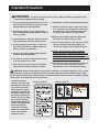
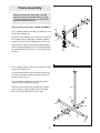
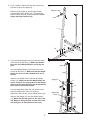
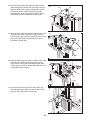
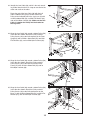
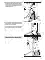
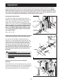
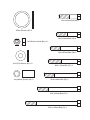
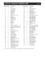
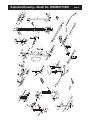
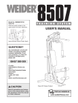
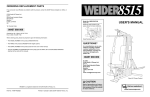
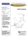
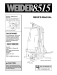
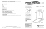
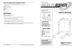
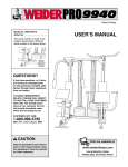
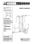
®
Model No. WEEMSY70080
Serial No.
Write the serial number in the
space above for future reference.
USERʼS MANUAL
Serial
Number
Decal
QUESTIONS?
As a manufacturer, we are
committed to providing
complete customer satisfaction.
If you have questions, or if
there are missing parts or damaged parts, please call:
08457-089009
Or write:
ICON Health & Fitness, Ltd.
Unit 4
Revie Road Industrial Estate
Revie Road
Beeston
Leeds LS118JG
UK
email: csuk@iconeurope.com
CAUTION
Read all precautions and instructions in this manual before using
this equipment. Save this manual
for future reference.
Patent Pending
w
Visit our website at
www.weiderfitness.com
®
Table of Contents
Important Precautions . . . . . . . . . . . . . . . . . . . . . . . . . . . . . . . . . . . . . . . . . . . . . . . . . . . . . . . . . . . . . . . . . . . . . . 3
Before You Begin . . . . . . . . . . . . . . . . . . . . . . . . . . . . . . . . . . . . . . . . . . . . . . . . . . . . . . . . . . . . . . . . . . . . . . . . . . 4
Assembly . . . . . . . . . . . . . . . . . . . . . . . . . . . . . . . . . . . . . . . . . . . . . . . . . . . . . . . . . . . . . . . . . . . . . . . . . . . . . . . . 5
Cable Diagram . . . . . . . . . . . . . . . . . . . . . . . . . . . . . . . . . . . . . . . . . . . . . . . . . . . . . . . . . . . . . . . . . . . . . . . . . . . 16
Adjustment . . . . . . . . . . . . . . . . . . . . . . . . . . . . . . . . . . . . . . . . . . . . . . . . . . . . . . . . . . . . . . . . . . . . . . . . . . . . . . 17
Weight Resistance Chart . . . . . . . . . . . . . . . . . . . . . . . . . . . . . . . . . . . . . . . . . . . . . . . . . . . . . . . . . . . . . . . . . . . 18
Maintenance and Trouble-shooting . . . . . . . . . . . . . . . . . . . . . . . . . . . . . . . . . . . . . . . . . . . . . . . . . . . . . . . . . . . 19
Part Identification Chart . . . . . . . . . . . . . . . . . . . . . . . . . . . . . . . . . . . . . . . . . . . . . . . . . . . . . . . . . . .End of Manual
Part List . . . . . . . . . . . . . . . . . . . . . . . . . . . . . . . . . . . . . . . . . . . . . . . . . . . . . . . . . . . . . . . . . . . . . . .End of Manual
Exploded Drawing . . . . . . . . . . . . . . . . . . . . . . . . . . . . . . . . . . . . . . . . . . . . . . . . . . . . . . . . . . . . . . .End of Manual
How to Order Replacement Parts . . . . . . . . . . . . . . . . . . . . . . . . . . . . . . . . . . . . . . . . . . . . . . . . . . . . . Back Cover
WEIDER is a registered trademark of ICON Health & Fitness, Inc.
2
Important Precautions
WARNING:
To reduce the risk of serious injury, read the following important precautions before using the training system.
8. Keep hands and feet away from moving parts.
1. It is the responsibility of the owner to ensure
that all users of the training system are adequately informed of all precautions.
9. Make sure that the cables remain on the pulleys at all times. If the cables bind while you
are exercising, stop immediately and make
sure the cables are on all of the pulleys.
2. Read all instructions in this manual and in
the accompanying literature before using the
training system.
10. Always wear athletic shoes for foot protection when using the training system.
3. If you feel pain or dizziness while exercising,
stop immediately and begin cooling down.
11. Never release the press arm, leg lever, lat bar,
row bar, or ankle strap while weights are
raised. The weights will fall with great force.
4. Use the training system only on a level surface. Cover the floor or carpet beneath the
training system for protection.
12. Always disconnect the lat bar or row bar
from the training system when performing an
exercise that does not use them. Do not
leave the lat bar or row bar on the high pulley
station. Store them in a safe place.
5. Inspect and tighten all parts often. Replace
any worn parts immediately.
6. The training system is designed to be used
by only one person at a time.
13. The training system is intended for home use
only. Do not use the training system in a
commercial, rental, or institutional setting.
7. Keep children under the age of 12 and pets
away from the training system at all times.
WARNING: Before beginning this or any exercise program, consult your physician. This is especially important for persons over the age of 35 or persons with pre-existing health problems. Read
all instructions before using. ICON assumes no responsibility for personal injury or property damage
sustained by or through the use of this product.
The warning decals
shown at the right have
been placed on the training system in the locations shown on page 4.
Familiarise yourself with
the decals before using
the training system. If a
decal is missing or illegible, call our Customer
Service Department and
order a free replacement
decal (see the front
cover of this manual).
Attach the replacement
decal in the location
shown on page 4.
Warning decal #1
Warning decal #2
Warning decal #3
3
Before You Begin
Thank you for selecting the versatile WEIDER® X2
Training System. The WEIDER® X2 offers a selection
of weight stations designed to develop every major
muscle group of the body. Whether your goal is to tone
your body, build dramatic muscle size and strength, or
improve your cardiovascular system, the WEIDER® X2
will help you to achieve the results you want.
toll-free at 08457-089009. To help us assist you,
please note the product model number and serial
number before calling. The model number is WEEMSY70080. The serial number can be found on a decal
attached to the WEIDER® X2 (see the front cover of
this manual).
Before reading further, please familiarise yourself
with the parts that are labelled in the drawing
below.
For your benefit, read this manual carefully before
using the WEIDER® X2. If you have additional questions, please call our Customer Service Department
Assembled
Dimensions:
Height: 201 cm
Width: 109 cm
Length: 142 cm
High Pulley Station
Warning Decal #3
Warning Decal #2
Warning Decal #1
Butterfly/Press Arm
Press Handles
Backrest
Seat
Weight Stack
Foam Pad
Leg Lever
Low Pulley Station
4
Assembly
Make sure you have the following tools:
Make Assembly Easier for Yourself!
• Two (2) adjustable spanners
Everything in this manual is designed to
ensure that the training system can be
assembled successfully by anyone. Before
beginning assembly, make sure to read the
information on this page; this brief introduction will save you much more time than
it takes to read it!
• One (1) standard screwdriver
• One (1) phillips screwdriver
• One (1) rubber mallet
• You will also need grease or petroleum jelly, a
small amount of soapy water, and clear tape or
masking tape.
Assembly Requires Two Persons
Note: Assembly will be more convenient if you have
a socket set, a set of open-end or closed-end
wrenches, or a set of ratchet wrenches.
For your convenience and safety, assemble the
training system with the help of another person.
Set Aside Enough Time
How to Identify Parts
Due to the many features of the training system,
the assembly process will require about three
hours. By setting aside plenty of time and by deciding to make the task enjoyable, assembly will go
smoothly. You may want to assemble the training
system over a couple of evenings.
To help you identify the small parts used in assembly,
we have included a PART IDENTIFICATION CHART
in the centre of this manual. Place the chart on the
floor and use it to easily identify parts during each
assembly step. Note: Some small parts may have
been pre-attached. If a part is not in the parts
bag, check to see if it has been pre-attached.
Select a Location for the Training
System
How to Orient Parts
Because of its weight and size, the training system
should be assembled in the location where it will be
used. Make sure that there is enough room to walk
around the training system as you assemble it.
As you assemble the training system, make sure
that all parts are oriented exactly as shown in the
drawings.
Tightening Parts
How to Unpack the Box
Tighten all parts as you assemble them, unless
instructed to do otherwise.
To make assembly as easy as possible, we have
divided the assembly process into four stages. The
parts needed for each stage are found in individual
bags. Important: Wait until you begin each stage
to open the parts bag for that stage. Place all
parts of the training system in a cleared area and
remove the packing materials. Do not dispose of
the packing materials until assembly is completed.
Questions?
If you have questions after reading the assembly
instructions, please call our Customer Service
Department at 08457-089009.
The Four Stages of the Assembly Process
Frame Assembly—You will begin by assembling
the base and the uprights that form the skeleton of
the home gym.
Arm Assembly—During this stage you will
assemble the arms and the leg lever.
Cable Assembly—During this stage you will
attach the cables and pulleys that connect the
arms to the weights.
Miscellaneous Assembly—During the final stage
you will assemble the seat and the backrest.
5
1.
Frame Assembly
1
Before you begin this step, make sure that
you have read all of the information on page
5. This introduction will save you much more
time than it takes to read it!
1
Open the parts bag labelled “FRAME ASSEMBLY.”
Press a 50mm Square Cover Cap (35) onto each end
of the Front Stabiliser (2).
Attach the Front Stabiliser (2) to the Base (1) with two
M8 x 70mm Carriage Bolts (64), a 50mm x 102mm
Support Plate (21), and two M8 Nylon Locknuts (70).
Place the Rear Stabiliser (3) on the floor and line up
the holes in the Rear Stabiliser with the holes in the
bracket on the Base (1).
21
64
2
Insert two M8 x 70mm Carriage Bolts (64) through a
50mm x 102mm Support Plate (21) and then through
the indicated holes in the Base (1). Place the Base on
the floor.
2. Press a 50mm Square Cover Cap (35) onto each end
of the Rear Stabiliser (3).
70
35
64
21
35
2
Press the 25mm x 50mm Cover Cap (53) onto the
indicated end of the Rear Upright (5).
5
Attach the Rear Stabiliser (3) and the Rear Upright
(5) to the Base (1) with two M8 x 70mm Carriage
Bolts (64) and two M8 Nylon Locknuts (70).
64
35
64
70
1
6
53
70
3
35
3. Press a 25mm x 50mm Inner Cap (39) into the support tube on the Front Upright (4).
3
Slide the Front Upright (4) onto the M8 x 70mm
Carriage Bolts (64) in the Base (1). Thread an M8
Nylon Locknut (70) onto each Carriage Bolt. Do not
tighten the Nylon Locknuts yet.
Support Tube
39
4
70
70
4. Place the Weight Bumpers (44) over the outer holes
in the bracket on the Base (1). Make sure that the
flat sides of the Weight Bumpers are facing the
floor.
Insert the Weight Guides (13) into the holes in the
bracket on the Base (1). Make sure that the Weight
Guides are turned so the indicated holes are at
the top.
Slide the nine Weight Plates (36) onto the Weight
Guides (13). Make sure that the Weight Plates are
turned correctly—the large grooves in the Weight
Plates must be facing the floor and the adjustment
holes must be on the side shown.
Press the Adjustment Tube Cap (43) into the lower
end of the Adjustment Tube (14). Insert the
Adjustment Tube into the stack of Weight Plates (36).
Slide the Top Weight (17) onto the Weight Guides
(13). Make sure that the groove in one side of the
Top Weight is facing the floor and that it fits over
the spring pins on the Adjustment Tube (14).
64
4
Holes
13
Spring Pin
17
14
43
Adjustment
Holes
36
44
1
7
1
5. Press a 50mm Square Inner Cap (37) into the end of
the Top Frame (6). Hold the Top Frame on the Rear
Upright (5) and the Front Upright (4). Make sure that
the Weight Guides (13) are in front of the indicated brackets on the Top Frame.
5
6
Attach the Top Frame (6) to the Front Upright (4) with
an M10 x 70mm Bolt (57) and an M10 Nylon Locknut
(60).
6. Attach one Weight Guide (13) to the indicated bracket on the Top Frame (6) with an M8 x 38mm Bolt
(67), an M8 Flat Washer (72), and an M8 Nylon
Locknut (70). Attach the other Weight Guide to the
Top Frame in the same manner.
4
6
37
57
70
13
41
6
Press a 25mm Round Inner Cap (41) into the top of
each Weight Guide (13).
7. Align the upper bracket on the Seat Frame (7) with
the indicated hole in the Front Upright (4). Attach the
Seat Frame with an M8 x 65mm Bolt (66) and an M8
Nylon Locknut (70).
21
60
Attach the Top Frame (6) to the Rear Upright (5) with
two M8 x 70mm Carriage Bolts (64), a 50mm x 102mm
Support Plate (21), and two M8 Nylon Locknuts (70).
Fully tighten all Nylon Locknuts used in steps 2
and 3.
64
Brackets
67
72
5
70
Bracket
13
7
4
Attach the lower bracket on the Seat Frame (7) to the
Front Upright (4) with an M8 x 65mm Bolt (66), an
M8 Flat Washer (72), and an M8 Nylon Locknut (70).
70
66
7
70
72
8
66
Arm Assembly
8
8. Open the parts bag labelled “ARM ASSEMBLY.”
Insert the indicated end of the Locking Plate (29) into
the slot in the support tube on the Front Upright (4).
Lubricate an M10 x 65mm Bolt (58). Attach the
Locking Plate to the indicated hole in the support tube
with the Bolt, two M10 Flat Washers (62), and an
M10 Nylon Locknut (60).
9. Press two 50mm Square Inner Caps (37) into the
Butterfly/Press Frame (9) as shown. Next, press two
25mm x 50mm Inner Caps (39) into the Butterfly/Press
Frame (9).
29
60
62
9
Lubricate an M10 x 125mm Bolt (51). Attach the
Butterfly/Press Frame (9) to the indicated holes in the
Top Frame (6) with the Bolt, two 10mm Flat Washers
(62), and an M10 Nylon Locknut (60). Make sure
that the indicated bracket is on the side shown.
Do not overtighten the Nylon Locknut; the
Butterfly/Press Frame must pivot easily.
Slot
60
62
Press a 25mm Round Inner Cap (41) into each end of
the Right Press Handle (20). Slide a 130mm
Handgrip (30) onto each end of the Right Press
Handle.
9
6
51
Lubricate
9
37
10
46
Press a 25mm Round Inner Cap (41) into the indicated hole in the Right Arm (11). Press a 2 3/4” Plastic
Sleeve (46) onto the round tube on the Right Arm.
Attach the Right Press Handle (20) to the Right Arm
(11) with two M8 x 60mm Carriage Bolts (65), a 38mm
x 102mm Support Plate (22), and two M8 Nylon
Locknuts (70).
58
62
Bracket
10. Press a 45mm Square Inner Cap (38) into each end
of the Right Arm (11). Wet the lower end of the Right
Arm with soapy water and slide a Short Foam Pad
(31) onto the Right Arm.
11
30
Lubricate
62
39
37
4
41
20
70
41
30
41
22
38
31
65
38
11. Insert the round tube on the Right Arm (11) into the
indicated hole in the Butterfly/Press Frame (9). While
a second person holds the Right Arm, place a 25mm
Washer (85) over the tube on the Right Arm. Attach
the Right Arm with an M6 x 35mm Screw (77) and an
M6 Nylon Locknut (79).
Press a 25mm Round Inner Cap (41) into the tube on
the Right Arm (11).
Attach the Left Arm (10, not shown) to the Butterfly/
Press Frame (9) as described in steps 10 and 11.
12. Press a 45mm Square inner Cap (38) into the top of
the Leg Lever (8).
Attach the Bumper (45) to the indicated hole in the
Leg Lever (8) with an ST5 x 15mm Screw (82).
11
13. Open the parts bag labelled “CABLE ASSEMBLY.”
Refer to the Cable Diagram on page 16 as you
assemble the Cables.
Identify the Butterfly Cable (47). It has a loop on each
end and it is about 271cm long. Wrap the Butterfly
Cable around a 90mm Pulley (50) in the direction
shown. Attach the Pulley and two Pulley Covers (28)
to a Butterfly Pulley Bracket (26) with an M10 x
50mm Bolt (54), an M10 Flat Washer (62), and an
M10 Nylon Locknut (60). Make sure that the Pulley
Bracket is turned exactly as shown.
14. Lubricate an M10 x 80mm Bolt (56). Attach the
Butterfly Pulley Bracket (26) to the indicated bracket
on the Front Upright (4) with the Bolt and an M10
Nylon Locknut (60). Make sure that the larger label
on the Pulley Covers (28) is facing forward.
Slide the loop on the end of the Butterfly Cable (47)
onto the welded hook on the semi-circular bracket
behind the Left Arm (10).
10
41
85
11
77
9
12
Lubricate an M10 x 70mm Bolt (57). Attach the Leg
Lever (8) to the bracket on the Seat Frame (7) with
the Bolt and an M10 Nylon Locknut (60). Do not
overtighten the Nylon Locknut; the Leg Lever
must pivot easily.
Cable Assembly
79
38
8
60
45
7
Lubricate
82
57
13
54
62
47
28
26
50
60
14
56
28
Welded
Hook
4
60
Lubricate
10
26
47
15. Wrap the Butterfly Cable (47) around a 90mm Pulley
(50) in the direction shown. Attach the Pulley and two
Pulley Covers (28) to the Pulley Frame (27) with an
M10 x 50mm Bolt (54) and an M10 Nylon Locknut
(60). Make sure that the small label on the Pulley
Covers is facing upward.
15
Important: Make sure that the Pulley Frame (27) is
oriented exactly as shown.
47
28
50
28
27
54
16. Wrap the Butterfly Cable (47) around a 90mm Pulley
(50) in the direction shown. Attach the Pulley and two
Pulley Covers (28) to a Butterfly Pulley Bracket (26)
with an M10 x 50mm Bolt (54), an M10 Flat Washer
(62), and an M10 Nylon Locknut (60). Make sure that
the Pulley Bracket is oriented exactly as shown.
Lubricate an M10 x 80mm Bolt (56). Attach the Butterfly
Pulley Bracket (26) to the bracket (not shown) on the
Front Upright (4) with the Bolt and an M10 Nylon
Locknut.
60
Wrap the High Cable (48) around a 90mm Pulley (50)
in the direction shown. Attach the Pulley inside the
slot in the Top Frame (6) with an M10 x 65mm Bolt
(58), two M10 Flat Washers (62), two Long Metal
Spacers (49), and an M10 Nylon Locknut (60).
11
60
26
Lubricate
28
28
47
Slide the loop on the end of the Butterfly Cable (47)
onto the welded hook (not shown) on the semi-circular bracket behind the Right Arm (11).
17. Identify the High Cable (48). It is about 236cm long
and it has a loop on one end and a ball on the other.
Route the end of the High Cable with the loop up
through the indicated slot in the Top Frame (6) from
below.
56
16
60
50
54
62
4
11
17
60
50
62
48
Slot
49
62
58
6
18. Route the end of the High Cable (48) with the loop
down through the indicated slot in the Top Frame (6).
Wrap the High Cable around a 90mm Pulley (50) in
the direction shown. Attach the Pulley inside the
welded bracket on the Top Frame (6) with an M10 x
45mm Bolt (59) and an M10 Nylon Locknut (60).
18
50
48
Slot
60
59
6
19. Wrap the High Cable (48) around a 90mm Pulley (50)
in the direction shown. Attach the Pulley and two
Pulley Covers (28) to the indicated holes in the Pulley
Plates (25) with an M10 x 50mm Bolt (54) and an
M10 Nylon Locknut (60).
19
54
25
20. Wrap the High Cable (48) around a 90mm Pulley (50)
in the direction shown. Attach the Pulley and two
Pulley Covers (28) inside the welded bracket under
the Top Frame (6) with an M10 x 50mm Bolt (54) and
an M10 Nylon Locknut (60).
20
60
28
25
6
60
28
28
50
21. Attach the loop on the end of the High Cable (48)
inside the Adjustment Tube (14) with an M8 x 35mm
Bolt (68) and an M8 Nylon Locknut (70).
21
48
48
14
68
12
48
50
70
54
22. Identify the Low Cable (40), which is the only remaining Cable. Note that there is a loop on one end of the
cable and a ball on the other.
Route the end of the Low Cable (40) with the ball
under a 90mm Pulley (50) as shown. Attach the
Pulley to the indicated hole in the Leg Lever (8) with
an M10 x 80mm Bolt (56), an M10 Flat Washer (62),
and an M10 Nylon Locknut (60). Make sure that the
Cable is between the Pulley and the bracket on
the Leg Lever.
23. Wrap the Low Cable (40) around a 90mm Pulley (50)
in the direction shown. Attach the Pulley and two
Pulley Covers (28) to the indicated hole in the Front
Upright (4) with an M10 x 95mm Bolt (55), two M10
Flat Washers (62), and an M10 Nylon Locknut (60).
22
60
8
62
23
62
56
50
40
60
4
50
28
28
40
24. Wrap the Low Cable (40) around a 90mm Pulley (50)
in the direction shown. Attach the Pulley and two
Pulley Covers (28) to the lower half of the Pulley
Frame (27) with an M10 x 50mm Bolt (54) and an
M10 Nylon Locknut (60).
24
13
55
27
60
28
50
25. Wrap the Low Cable (40) around a 90mm Pulley (50)
in the direction shown. Attach the Pulley and two
Pulley Covers (28) to the indicated bracket on the
Base (1) with an M10 x 50mm Bolt (54), an M10 Flat
Washer (62), and an M10 Nylon Locknut (60).
62
54
40
28
25
60
40
1
28
50
62
28
54
26. Wrap the Low Cable (40) around a 90mm Pulley (50)
in the direction shown. Attach the Pulley and two
Pulley Covers (28) to the lowest holes in the Pulley
Plates (25) with an M10 x 50mm Bolt (54) and an
M10 Nylon Locknut (60).
26
54
25
28
50
60
28
40
27. Thread an M8 Plain Nut (71) halfway onto the M8 x
75mm Eyebolt (69). Slide the loop on the end of the
Low Cable (40) onto the Eyebolt.
27
Attach the M8 x 75mm Eyebolt (69) to the indicated
bracket on the Front Upright (4) with an M8 Nylon
Locknut (70).
40
4
69
Make sure that the three cables are in the grooves
of all pulleys and that the cables and the pulleys
move smoothly.
Miscellaneous Assembly
28. Open the parts bag labelled “SEAT ASSEMBLY.”
70
28
4
Attach the Backrest (18) to the Front Upright (4) with
two M6 x 65mm Screws (76) and two M6 Flat
Washers (80).
76
80
18
14
71
76
29. Insert an M6 x 38mm Carriage Bolt (74) into the centre
hole in each Seat Plate (23). Attach each Seat Plate
to the Seat (19) with two M6 x 15mm Screws (78).
29
Turn the Seat (19) so the wide end is in the position
shown. Insert the two M6 x 38mm Carriage Bolts (74)
into the indicated holes in the Seat Frame (7). Secure
the Carriage Bolts with two M6 Flat Washers (80) and
two M6 Nylon Locknuts (79).
30. Press a 19mm Round Inner Cap (42) into each end of
the Long Pad Tube (83) and the Short Pad Tube (84).
7
30
Slide the Long Pad Tube (83) into the holes in the
bracket on the Seat Frame (7). Slide a Large Foam
Pad (32) onto each end of the Long Pad Tube.
Slide the Short Pad Tube (84) into the hole in the Leg
Lever (8). Slide a Narrow Foam Pad (33) onto each
end of the Short Pad Tube.
19
42
42
33
74
23
23
74
78
78
32
80
79
83
7
32
84
42
8
33
42
31. Make sure that all parts have been properly tightened. The use of the remaining parts will be explained in
ADJUSTMENT, beginning on page 17 of this manual.
Before using the training system, pull each cable a few times to make sure that the cables move smoothly
over the pulleys. If one of the cables does not move smoothly, find and correct the problem. IMPORTANT: If
the cables are not properly installed, they may be damaged when heavy weight is used. If there is
any slack in the cables, you will need to remove the slack by tightening the cables. See MAINTENANCE AND TROUBLE-SHOOTING on page 19.
15
Cable Diagram
The cable diagram below shows the proper routing of the High Cable (48), the Butterfly Cable (47), and the Low
Cable (40). The numbers show the correct route for each Cable. Make sure that the Cables are routed correctly, that the pulleys move smoothly, and that the pulley covers do not touch or bind the Cables.
Incorrect cable routing can damage the training system.
A-1
A-2
A-4
High Cable (A)
Butterfly Cable (B)
A-3
B-3
C-5
B-1
C-6
A-5
B-2
C-3
C-2
C-1
Low Cable (C)
Cable ID Chart
High Cable (48)—236cm
Butterfly Cable (47)—271cm
Low Cable (40)—298cm
16
C-4
Adjustment
The instructions below describe how each part of the training system can be adjusted. Refer to the exercise
guide accompanying this manual to see how the training system should be set up for each exercise. IMPORTANT: When attaching the lat bar, row bar, ankle strap, or handle, make sure that the attachments are in
the correct starting position for the exercise to be performed. If there is any slack in the cables or chain
as an exercise is performed, the effectiveness of the exercise will be reduced.
Changing the Weight Setting
To change the setting of the weight stack, insert the
Weight Pin (75) under the desired Weight Plate (36). Be
sure to insert the Weight Pin fully. The setting of the
weight stack can be changed from 6 pounds to 118.5
pounds, in increments of 12.5 pounds. Note: Due to the
cables and pulleys, the amount of resistance at each
exercise station may vary from the weight setting.
Refer to the WEIGHT RESISTANCE CHART on page
18 to find the approximate amount of resistance at
each weight station.
75
Note: 1 kg = 2,2 lbs
Attaching the Lat Bar, Row Bar, Ankle Strap, or Handle
to the High Pulley Station or the Low Pulley Station
The Lat Bar (15), Row Bar (16), Ankle Strap (52), or
Handle (61) can be attached to the High Cable (48, not
shown) or the Low Cable (40) with a Cable Clip (73). For
some exercises, the Chain (63) should be connected
between the attachment and the Cable with two Cable
Clips. Adjust the length of the Chain between the
attachment and the Cable so that the attachment is in
the correct starting position for the exercise to be
performed.
61
63
73
WARNING: Always disconnect the lat
bar or row bar from the training system when
performing an exercise that does not use these
attachments.
16
Setting Up the Training System for Butterfly
Exercises
To use the Arms (10, 11) for butterfly exercises, pivot the
Locking Plate (29) down into the slot in the Butterfly/Press
Frame (9). This will allow the Arms to pivot forward but
will prevent the Butterfly/Press Frame from moving.
11
73
40
52
15
9
29
17
36
Slot
10
Setting Up the Training System for Press Exercises
To use the Arms (10, 11) for press exercises, first lift the
Locking Plate (29) until it disengages the slot in the
Butterfly/Press Frame (9). Insert the Butterfly Locking
Pins (81) into the indicated holes in the Butterfly/Press
Frame (9) and down into the Arms. This will allow the
Butterfly/Press Frame and the Arms to swing forward
together.
11
81
9
Slot
29
10
Locking the Weight Stack
To prevent unauthorised use of the training system, insert
the Locking Bar (34) into the indicated hole in one of the
Weight Guides (13) and secure the Locking Bar with the
Lock (24).
13
24
Holes
34
Weight Resistance Chart
The chart at the right shows the
approximate weight resistance at
each weight station. “Top” refers to
the 6-lb. top weight; the other numbers refer to the 12.5-lb. weight
plates. Note: The actual resistance
at each weight station may vary
due to differences in individual
weight plates, as well as friction
between the cables, pulleys, and
weight guides.
Note: 1 kg = 2,2 lbs
Weight
Plates
Press
Arm
(lbs.)
High
Pulley
(lbs.)
Butterfly
Arm
(lbs.)
Leg Lever/
Low Pulley
(lbs.)
1
31
29
44
34
Top
19
2
43
3
55
16
43
57
25
63
20
48
82
62
120
90
4
68
71
101
6
92
99
139
104
177
132
5
80
7
105
9
129
8
117
18
85
113
158
141
196
127
76
118
146
Maintenance and Trouble-shooting
Inspect and tighten all parts each time you use the training system. Replace any worn parts immediately.
The training system can be cleaned using a damp cloth and mild non-abrasive detergent. Do not use solvents.
Tightening the Cables
Woven cable, the type of cable used on the training system,
can stretch slightly when it is first used. If there is any
slack in the cables before resistance is felt, the cables
should be tightened.
Slack can be removed by moving one or both of the
Pulleys (50) attached to the Pulley Plates (25) to different
holes in the Pulley Plates. To do this, remove the M10 x
50mm Bolt (54) and the M10 Nylon Locknut (60). Move
the Pulley and the Pulley Covers (28) one hole up or
down and re-attach them with the Bolt and Nylon
Locknut. Make sure that the Low Cable (40) or the
High Cable (48) is in the groove of the Pulley.
After moving one of the Pulleys (50) one hole up or down,
test the training system to see if the cables are tight. If
the cables are still loose, move the second Pulley one
hole. Repeat this process until the cables are tight.
Additional slack can be removed by adjusting the M8 x
75mm Eyebolt (69) to which the Low Cable (40) is
attached. To do this, loosen the M8 Nylon Locknut (70)
without removing it. Then, tighten the M8 Plain Nut (70)
further onto the Eyebolt. Finally, retighten the M8 Nylon
Locknut.
Note: If a cable tends to slip off the pulleys often, the
cable may have become twisted. Remove the cable
and re-install it.
If the cables need to be replaced, see ORDERING
REPLACEMENT PARTS on the back cover of this manual.
19
54
28
40
48
50
25
60
50
28
4
40
69
70
71
Part Identification Chart—WEEMSY70080
R0601A
M6 Nylon Locknut (79)–4
M6 Flat Washer (80)–4
ST5 x 15mm Screw (82)–1
M8 Flat Washer (72)–3
M8 Nylon Locknut (70)–18
M8 Plain Nut (71)–1
M8 x 35mm Bolt (68)–1
M8 x 38mm Bolt (67)–2
M6 x 65mm Screw (76)–2
M6 x 38mm Carriage Bolt (74)–2
M6 x 35mm Screw (77)–2
M6 x 15mm Screw (78)–4
M8 x 60mm Carraige Bolt (65)–4
M8 x 65mm Bolt (66)–2
M8 x 70mm Carriage Bolt (64)–8
M10 x 45mm Bolt (59)–1
25mm Washer (85)–2
M10 Nylon Locknut (60)–18
M10 x 50mm Bolt (54)–8
M10 x 65mm Bolt (58)–2
M10 Flat Washer (62)–12
Long Metal Spacer (49)–2
M10 x 70mm Bolt (57)–2
M10 x 80mm Bolt (56)–3
M10 x 95mm Bolt (55)–1
M10 x 125mm Bolt (51)–1
Weight Bumper (44)–2
50mm Square Cover Cap (35)–4
Bumper (45)–1
25mm x 50mm Cover Cap (53)–1
25mm x 50mm Inner Cap (39)–3
45mm Square Inner Cap (38)–5
Adjustment Tube Cap (43)–1
2 3/4” Plastic Sleeve (46)–2
25mm Round Inner Cap (41)–14
50mm Square Inner Cap (37)–3
19mm Round Inner Cap (42)–4
Part List—Model No. WEEMSY70080
Key No. Qty.
1
2
3
4
5
6
7
8
9
10
11
12
13
14
15
16
17
18
19
20
21
22
23
24
25
26
27
28
29
30
31
32
33
34
35
36
37
38
39
40
41
42
43
44
1
1
1
1
1
1
1
1
1
1
1
1
2
1
1
1
1
1
1
1
3
2
2
1
2
2
1
18
1
8
2
2
2
1
4
9
3
5
3
1
14
4
1
2
Description
Base
Front Stabiliser
Rear Stabiliser
Front Upright
Rear Upright
Top Frame
Seat Frame
Leg Lever
Butterfly/Press Frame
Left Arm
Right Arm
Left Press Handle
Weight Guide
Adjustment Tube
Lat Bar
Row Bar
Top Weight
Backrest
Seat
Right Press Handle
50mm x 102mm Support Plate
38mm x 102mm Support Plate
Seat Plate
Lock
Pulley Plate
Butterfly Pulley Bracket
Pulley Frame
Pulley Cover
Locking Plate
130mm Handgrip
Short Foam Pad
Large Foam Pad
Narrow Foam Pad
Locking Bar
50mm Square Cover Cap
Weight Plate
50mm Square Inner Cap
45mm Square Inner Cap
25mm x 50mm Inner Cap
Low Cable
25mm Round Inner Cap
19mm Round Inner Cap
Adjustment Tube Cap
Weight Bumper
Key No. Qty.
45
46
47
48
49
50
51
52
53
54
55
56
57
58
59
60
61
62
63
64
65
66
67
68
69
70
71
72
73
74
75
76
77
78
79
80
81
82
83
84
85
#
1
2
1
1
2
12
1
1
1
8
1
3
2
2
1
18
1
12
1
8
4
2
2
1
1
18
1
3
2
2
1
2
2
4
4
4
2
1
1
1
2
1
R0601A
Description
Bumper
2 3/4” Plastic Sleeve
Butterfly Cable
High Cable
Long Metal Spacer
90mm Pulley
M10 x 125mm Bolt
Ankle Strap
25mm x 50mm Cover Cap
M10 x 50mm Bolt
M10 x 95mm Bolt
M10 x 80mm Bolt
M10 x 70mm Bolt
M10 x 65mm Bolt
M10 x 45mm Bolt
M10 Nylon Locknut
Handle
M10 Flat Washer
Chain
M8 x 70mm Carriage Bolt
M8 x 60mm Carriage Bolt
M8 x 65mm Bolt
M8 x 38mm Bolt
M8 x 35mm Bolt
M8 x 75mm Eyebolt
M8 Nylon Locknut
M8 Plain Nut
M8 Flat Washer
Cable Clip
M6 x 38mm Carriage Bolt
Weight Pin
M6 x 65mm Screw
M6 x 35mm Screw
M6 x 15mm Screw
M6 Nylon Locknut
M6 Flat Washer
Butterfly Locking Pin
ST5 x 15mm Screw
Long Pad Tube
Short Pad Tube
25mm Washer
Userʼs Manual
Note: “#” indicates a non-illustrated part. Specifications are subject to change without notice.
30
70
30
41
41
60
42
60
20
77
22
38
40
31
38
41
8
62
33
11
46
47
50
56
82
77
38
12
9
62
41
85
70
45
84
57
65
79
81
37
60
33
41
30
81
42
41
46
39
79
85
41
62
31
38
10
47
37
51
22
73
42
65
62
49
60
32
48
83
49
62
63
7
19
78
32
70
80
78
42
28
60
54
26
59
28
79
50
56
50
50
74
23
28
28
60
60
60
58
52
50
79
62
6
35
70
23
74
54
2
18
37
21
64
64
21
66
62
60
39
62
60
4
70
29
60
70
70
28
72
70
50
1
28
66
76
80
76
64
62
60
71
40
58
54
69
35
54
62
57
50
50
28
35
21
55
28
62
28
60
28
50
50
28
60
27
56
70
3
28
28
28
62
54
60
30
70
60
26
54
67
72
30
44
41
75
36
43
68
17
48
41
41
41
16
70
14
54
34
13
70
30
15
28
35
64
24
70
25
61
50
28
28
30
41
5
70
28
50
64
53
25
60
Exploded Drawing—Model No. WEEMSY70080
R0601A
How to Order Replacement Parts
To order replacement parts, contact the ICON Fitness Lifestyle Ltd. office, or write:
ICON Health & Fitness, Ltd.
Unit 4
Revie Road Industrial Estate
Revie Road
Beeston
Leeds LS11 8JG
UK
Tel:
08457-089009
Fax: 0113-2411120
When ordering parts, please be prepared to give the following information:
• The MODEL NUMBER of the product (WEEMSY70080)
• The NAME of the product (WEIDER® X2 training system)
• The SERIAL NUMBER of the product (see the front cover of this manual)
• The KEY NUMBER and DESCRIPTION of the part(s) (see the PART LIST and EXPLODED DRAWING
attached in the centre of this manual).
Part No. 161499 R0601A
Printed in China © 2001 ICON Health & Fitness, Inc.