1
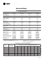
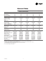
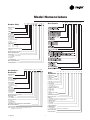
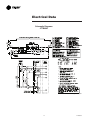
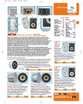
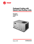
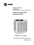
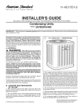
Split System Cooling Product Data XB144TTB4 1 1/2 - 5 Tons (018E - 061E) PUB. NO. 22-1833-09 Features and Benefits • CLIMATUFF® compressor • Efficiency up to 16.0 SEER • All aluminum SPINE FIN™ coil • WEATHERGUARD™ fasteners • QUICK-SESS™ cabinet, service access and refrigerant connections with full coil protection • DURATUFF™ base, fast complete drain, weatherproof • COMFORT-R™ mode approved • Glossy corrosion resistant finish • Internal compressor high/low pressure & temperature protection • 018, 024 & 030 ship with start kit • Liquid line filter/drier © 2012 Trane 2 • Polyslate gray cabinet with anthracite gray badge and cap • High pressure switch • Service valve cover • R-410A refrigerant • S.E.E.T. design testing • 100% line run test • Low ambient cooling to 30°F with AY28X079 • Low ambient cooling to 55°F as shipped • Extended warranties available 22-1833-09 Features and Benefits General Data Product Specifications A-Weighted Sound Power Level [dB(A)] Accessory Description and Usage AHRI Standard Capacity Rating Conditions 2 4 4 4 6 6 Model Nomenclature 7 Electrical Data 8 Dimensions13 Mechanical Specification Options 16 22-1833-093 General Data Product Specifications Model No. 1 4TTB4018E14TTB4024E14TTB4030E14TTB4036E1 Electrical Data V/Ph/Hz 2 208/230/1/60208/230/1/60208/230/1/60208/230/1/60 Min Cir Ampacity 9 9 12 19 Max Fuse Size (Amps) 15 15 20 30 ® ® ® CompressorsCLIMATUFF CLIMATUFF CLIMATUFF CLIMATUFF® - SCROLL No. Used - No. Stages 1-1 1-1 1-1 1-1 RL AMPS - LR AMPS 6.4 - 38.6 6.8 - 38.6 9.1 - 57.8 14.1 - 77 Outdoor Fan FL Amps 0.74 0.74 0.93 0.93 Fan HP 1/81/81/51/5 Fan Dia (inches) 23 23 27.6 27.6 Coil Spine Fin™ Spine Fin™ Spine Fin™ Spine Fin™ Refrigerant R-410A5/2-LB/OZ6/3-LB/OZ7/0-LB/OZ7/4-LB/OZ Line Size - (in.) O.D. Gas 3 5/83/43/43/4 Line Size - (in.) O.D. Liquid 3 3/83/83/83/8 Dimensions H x W x D (Crated) 34 x 30.1 x 33 34 x 30.1 x 33 38.4 x 35.1 x 38.7 42.4 x 35.1 x 38.7 Weight - Shipping 200 201 234 228 Weight - Net 173 174 201 193 Start Components YESYESYES NO Sound Enclosure YESYESYES NO Compressor Sump Heat NO NO NO NO Optional Accessories: 4 Anti-short Cycle Timer TAYASCT501ATAYASCT501ATAYASCT501ATAYASCT501A Evaporator Defrost Control A/C AY28X079 AY28X079 AY28X079 AY28X079 Rubber Isolator Kit BAYISLT101 BAYISLT101 BAYISLT101 BAYISLT101 Crank Case Heater Kit BAYCCHT300 BAYCCHT300 BAYCCHT300 BAYCCHT302 Hard Start Kit Scroll BAYKSKT260 Extreme Condition Mounting Kit BAYECMT023 BAYECMT023 BAYECMT004 BAYECMT004 Snow Leg - Base & Cap 4" High BAYLEGS002 BAYLEGS002 BAYLEGS002 BAYLEGS002 Snow Leg - 4" Extension BAYLEGS003 BAYLEGS003 BAYLEGS003 BAYLEGS003 Seacoast Kit BAYSEAC001BAYSEAC001BAYSEAC001BAYSEAC001 Refrigerant Lineset 5TAYREFLN950 TAYREFLN7* TAYREFLN7* TAYREFLN7* 1 Certified in accordance with the Air-Source Unitary Heat Pump Equipment certification program which is based on AHRI Standard 210/240. 2 Calculated in accordance with N.E.C. Only use HACR circuit breakers or fuses. 3 Standard line lengths - 80'. Standard lift - 60' Suction and Liquid line. For Greater lengths and lifts refer to refrigerant piping software Pub# 32-3312-0†. (†denotes latest revision) 4 For accessory description and usage, see pages 5 and 6. 5 * = 15, 20, 25, 30, 40 and 50 foot lineset available. A-Weighted Sound Power Level [dB(A)] MODEL SOUND POWER LEVEL [dB(A)] A_WEIGHTED FULL OVTAVE SOUND POWER LEVEL dB - [dB(A)] 63 125 250 500 1000 2000 4000 8000 4TTB4018E 79 24.9 44.9 56.7 71.1 74.1 72.7 62.2 49.9 4TTB4024E 79 23 45.4 57 70.9 74.2 70.5 62.9 52.6 4TTB4030E 80 27.9 52.9 62.9 74.3 76.2 73 64.7 52.5 4TTB4036E 78 23.2 51.7 64.2 72.3 74.1 71.3 62.7 49.5 4TTB4042E 80 22.8 52.8 65.6 73.3 75.1 75.1 62.8 50 4TTB4048E 80 22.8 52.8 65.6 73.3 75.1 75.1 62.8 50 4TTB4049E 76 44.3 53.8 56.6 63.6 34.6 59.9 52.7 43.7 4TTB4060E 80 22.8 52.8 65.6 73.3 75.1 71.5 62.8 50 4TTB4061E 76 42.2 53.8 57.8 66 65.7 57.7 58.4 51.7 Note: Rated in accordance with AHRI Stnadard 270-2008 4 22-1833-09 General Data Product Specifications Model No. 1 4TTB4042E14TTB4048E14TTB4049E14TTB4060E14TTB4061E1 Electrical Data V/Ph/Hz 2 208/230/1/60208/230/1/60208/230/1/60208/230/1/60 230/1/60 Min Cir Ampacity 2326263445 Max Fuse Size (Amps) 4045456060 Compressors CLIMATUFF® - SCROLLCLIMATUFF® - SCROLLCLIMATUFF® - SCROLLCLIMATUFF® - SCROLL CLIMATUFF® - SCROLL No. Used - No. Stages 1-1 1-1 1-1 1-1 1-2 RL AMPS - LR AMPS 17.9 - 112 19.9 - 109 19.9 - 109 26.4 - 134 32.1 - 152.9 Outdoor Fan FL Amps 0.93 0.93 1.0 0.93 2.80 Fan HP 1/51/51/51/51/3 Fan Dia (inches) 27.627.627.627.627.6 Coil Spine Fin™ Spine Fin™ Spine Fin™ Spine Fin™ Spine Fin™ Refrigerant R-410A 8/4-LB/OZ 8/5-LB/OZ11/9-LB/OZ8/8-LB/OZ12/9-LB/OZ Line Size - (in.) O.D. Gas 3 7/87/87/87/81-1/8 Line Size - (in.) O.D. Liquid 3 3/83/83/83/83/8 Dimensions H x W x D (Crated) 46.4 x 35.1 x 38.7 51 x 35.1 x 38.7 51 x 35.1 x 38.7 51 x 35.1 x 38.7 51 x 35.1 x 38.7 Weight - Shipping 272282304285312 Weight - Net 235245267248275 Start Components NONONONONO Sound Enclosure NONONONONO Compressor Sump Heat NONONONONO Optional Accessories: 4 Anti-short Cycle Timer TAYASCT501ATAYASCT501ATAYASCT501ATAYASCT501ATAYASCT501A Evaporator Defrost Control A/C AY28X079AY28X079AY28X079AY28X079AY28X079 Rubber Isolator Kit BAYISLT101BAYISLT101BAYISLT101BAYISLT101BAYISLT101 Crank Case Heater Kit BAYCCHT301BAYCCHT301BAYCCHT301BAYCCHT301BAYCCHT301 Hard Start Kit Scroll BAYKSKT260 BAYKSKT260 BAYKSKT260 Extreme Condition Mounting Kit BAYECMT004BAYECMT004BAYECMT004BAYECMT004BAYECMT004 Snow Leg - Base & Cap 4" High BAYLEGS002 BAYLEGS002 BAYLEGS002 BAYLEGS002 BAYLEGS002 Snow Leg - 4" Extension BAYLEGS003 BAYLEGS003 BAYLEGS003 BAYLEGS003 BAYLEGS003 Seacoast Kit BAYSEAC001BAYSEAC001BAYSEAC001BAYSEAC001BAYSEAC001 Refrigerant Lineset 5 TAYREFLN3*TAYREFLN3*TAYREFLN3*TAYREFLN3*TAYREFLN*4 1 Certified in accordance with the Air-Source Unitary Heat Pump Equipment certification program which is based on AHRI Standard 210/240. 2 Calculated in accordance with N.E.C. Only use HACR circuit breakers or fuses. 3 Standard line lengths - 60'. Standard lift - 60' Suction and Liquid line. For 061 units, Max. linear length 60 ft.; Max. lift - Suction 25 ft.; Max lift - Liquid 25 ft. For Greater lengths and lifts refer to refrigerant piping software Pub# 32-3312-0†. (†denotes latest revision) 4 For accessory description and usage, see pages 5 and 6. 5 * = 15, 20, 25, 30, 40 and 50 foot lineset available. 22-1833-09 5 General Data AHRI Standard Capacity Rating Conditions Accessory Description and Usage Anti-Short Cycle Timer — Solid state timing device that prevents compressor recycling until 5 minutes have elapsed after satisfying call or power interruptions. Use in area with questionable power delivery, commercial applications, long lineset, etc. AHRI STANDARD 210/240 RATING CONDITIONS — Evaporator Defrost Control — SPST Temperature actuated switch that cycles the condenser off as indoor coil reaches freeze-up conditions. Used for low ambient cooling to 30°F with TXV. (Noise rating numbers are determined with the unit in cooling operation.) Standard Noise Rating number is at 95°F outdoor air. (A) Cooling 80°F DB, 67°F WB air entering indoor coil, 95°F DB air entering outdoor coil. AHRI STANDARD 270 RATING CONDITIONS — Rubber Isolators — 5 large rubber donuts to isolate condensing unit from transmitting energy into mounting frame or pad. Use on any application where sound transmission needs to be minimized. Hard Start kit — Start capacitor and relay to assist compressor motor startup. Use in areas with marginal power supply, on long linesets, low ambient conditions, etc. Extreme Condition Mount Kit — Bracket kits to securely mount condensing unit to a frame or pad without removing any panels. Use in areas with high winds, or on commercial roof tops, etc. 6 22-1833-09 Model Nomenclature Outdoor Units Gas Furnaces 4 T T B 4 0 3 6 E 1 0 0 0 A A T U D 2 B 0 8 0 A C V 3 2 A A Refrigerant Type 2 = R-22 4 = R-410A TRANE Product Type W = Split Heat Pump T = Split Cooling Product Family Z = Leadership – Two Stage X = Leadership R = Replacement/Retail B = Basic A = Light Commercial Family SEER 0 = 10 3 = 13 1 = 11 4 = 14 2 = 12 5 = 15 6 = 16 8 = 18 9 = 19 Split System Connections 1-6 Tons 0 = Brazed Nominal Capacity in 000s of BTUs Major Design Modifications Power Supply 1 = 200-230/1/60 or 208-230/1/60 3 = 200-230/3/60 4 = 460/3/60 Secondary Function Minor Design Modifications Unit Parts Identifier Air Handlers – Residential 4 T E E 3 F 3 6 A 1 0 0 0 A A Coils – Residential Refrigerant Type 4 = R-410A T X C B 0 0 Refrigerant Type 4 - R410A Application TE = Fully Convertible TG = Semi Convertible TF = Front Return Product Family T-Premium (Heat Pump or Convertible Coil) Coil Design X - Direct Expansion Evaporator Coil Product Family E = Leadership – Variable Speed P = Leadership C = Replacement/Retail B = Basic Flow Control 0 = No Flow Control 3 = Nonbleed TXV Feature Identifier 0 = Standard Unit F = Air-Tite™ Nominal Capacity in 1000’s (BTUH) Major Design Change Power Supply 1 = Single Phase Electrical Connection 0 = Pig Tails B = Circuit Breaker D = Pull Disconnect Future Option – Factory Installed Heater Nominal KW Value Minor Design Modifications Unit Parts Identifier NOTE: There will be a phase-in of new model numbers for new air handlers over next 2 years. Product Family C - Cased A Coil A - Uncased A Coil F - Cased Horizontal Flat Coil Coil Width (Cased/Uncased) A - 14.5" / 13.3" B - 17.5" / 16.3" C - 21.0" / 19.8" D - 24.5" / 23.3" H - 10.5" Refrigerant Line Coupling 0 - Brazed Model Number Distinguisher Major Design Change Efficiency C - Standard S - Hi Efficiency (Derived from 10 SEER products) Refrigerant Control 3 - TXV - Non-Bleed Coil Circuitry H - Heat Pump Airflow Configuration A - Upflow Only U - Upflow / Downflow H - Horizontal Only C - Convertible - Upflow, Downflow, Left or Right Airflow Minor Design Change Unit Parts Identifier 22-1833-09 4 7 1 C C 3 H C A A Electrical Data Schematic Diagrams 4TTB4018, 4TTB4024, 4TTB4030 From Drawing D157123P01REV0 822-1833-09 Electrical Data Schematic Diagrams 4TTB4036, 4TTB4042 From Drawing D157124P01 22-1833-099 Electrical Data Schematic Diagrams 4TTB4048, 4TTB4049 From Drawing D157125P01 1022-1833-09 Electrical Data Schematic Diagrams 4TTB4060 From Drawing D157126P01 22-1833-0911 Electrical Data Schematic Diagrams 4TTB4061 From Drawing D156975p01 1222-1833-09 Dimensions 4TTB4 Outline Drawing Note: All dimensions are in MM (Inches). MODELS BASE A B C D E F G H J K 4TTB4018E 3 730 (28-3/4) 829 (32-5/8) 756 (29-3/4) 5/8 3/8 127 (5) 76 (3) 197 (7-3/4) 57 (2-1/4) 508 (20) 4TTB4024E 3 730 (28-3/4) 829 (32-5/8) 756 (29-3/4) 3/4 3/8 127 (5) 76 (3) 197 (7-3/4) 57 (2-1/4) 508 (20) 4TTB4030E 4 841 (33-1/8) 946 (37-1/4) 870 (34-1/4) 3/4 3/8 152 (6) 98 (3-7/8) 219 (8-5/8) 86 (3-3/8) 508 (20) 4TTB4036E 4 943 (37-1/8) 946 (37-1/4) 870 (34-1/4) 3/4 3/8 152 (6) 98 (3-7/8) 219 (8-5/8) 86 (3-3/8) 508 (20) 4TTB4042E 4 1045 (41 1/8) 946 (37-1/4) 870 (34-1/4) 7/8 3/8 152 (6) 98 (3-7/8) 219 (8-5/8) 86 (3-3/8) 508 (20) 4TTB4048E 4 1147 (45 1/8) 946 (37-1/4) 870 (34-1/4) 7/8 3/8 152 (6) 98 (3-7/8) 219 (8-5/8) 86 (3-3/8) 508 (20) 4TTB4049E 4 1147 (45 1/8) 946 (37-1/4) 870 (34-1/4) 7/8 3/8 152 (6) 98 (3-7/8) 219 (8-5/8) 86 (3-3/8) 508 (20) 4TTB4060E 4 1147 (45 1/8) 946 (37-1/4) 870 (34-1/4) 7/8 3/8 152 (6) 98 (3-7/8) 219 (8-5/8) 86 (3-3/8) 508 (20) 4TTB4061E 4 1147 (45 1/8) 946 (37-1/4) 870 (34-1/4) 1-1/8 3/8 152 (6) 98 (3-7/8) 219 (8-5/8) 86 (3-3/8) 508 (20) From Dwg. D156010 22-1833-0913 Notes 1422-1833-09 Notes 22-1833-09 15 Mechanical Specification Options General Condenser Coil The 4TTB4 is fully charged from the factory for up to 15 feet of piping. This unit is designed to operate at outdoor ambient temperatures as high as 115°F. Cooling capacities are matched with a wide selection of air handlers and furnace coils that are AHRI certified. The unit is certified to UL 1995. Exterior is designed for outdoor application. The outdoor coil provides low airflow resistance and efficient heat transfer. The coil is protected on all four sides by louvered panels. Casing Unit casing is constructed of heavy gauge, G90 galvanized steel and painted with a weather-resistant powder paint on all louvers, panels, prepaint on all other panels. Corrosion and weatherproof CMBP-G30 DuraTuff™ base. Low Ambient Cooling As manufactured, this unit has a cooling capability to 55°F. The addition of an evaporator defrost control with TXV permits low ambient cooling to 30° F. Accessories Thermostats — Cooling only and heat/cooling (manual and automatic changeover). Sub-base to match thermostat and locking thermostat cover. Refrigerant Controls Refrigeration system controls include condenser fan and compressor contactor. High and low pressure controls are inherent to the compressor. A factory installed liquid line drier is standard. Compressor The Climatuff® compressor features internal over temperature and pressure protection and total dipped hermetic motor. Other features include: roto lock suction and discharge refrigerant connections, centrifugal oil pump and low vibration and noise. Trane www.trane.com 01/12 The manufacturer has a policy of continuous product and product data improvement and it reserves the right to change design and specifications without notice.