Download Sony FWD-S47H1 User's Manual


Transcript
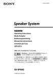
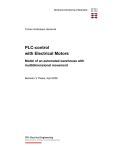
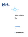
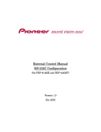
FLAT WIDE DISPLAY MONITOR
FWD-S47H1/S42H1
PROTOCOL MANUAL (For Customer)
Table of Contents
1. RS-232C
3. ID Talk
1.
Communication Parameters................................................ 1
1.
Default Setting.................................................................. 33
2.
Pin Assignment.................................................................... 1
2.
Setting Items...................................................................... 34
3.
Communication Data Format.............................................. 1
3.
Packet Structure................................................................ 34
4.
General Function................................................................. 3
5.
Analog Signal Detect Function........................................... 8
6.
Priority Signal Select Function........................................... 9
7.
Picture/Sound.................................................................... 13
8.
Size/Shift........................................................................... 16
9.
Status Enquiry................................................................... 20
10.
User Reset......................................................................... 26
2. SNMP
3-1.
3-2.
3-3.
3-4.
3-5.
4.
Header...................................................................... 34
Community.............................................................. 35
Command................................................................. 35
Request.................................................................... 35
Response.................................................................. 35
Requests and Responses.................................................... 36
4-1.
4-2.
4-3.
Requests................................................................... 36
Responses................................................................ 36
SET request.............................................................. 36
4-4.
4-5.
GET request............................................................. 36
ERROR response..................................................... 37
1.
SNMP................................................................................ 27
2.
Specifications of SNMP Installation................................. 28
3.
Installation......................................................................... 28
5.
Items.................................................................................. 37
5-1.
80**h....................................................................... 37
5-2.
90**h....................................................................... 38
5-3.
F100h....................................................................... 38
4.
Operation of SNMP Setting Window................................ 28
6.
4-1.
4-2.
4-3.
Community.............................................................. 29
Authentication Trap................................................. 30
IP Restriction of Host.............................................. 30
5.
MIB to Be Installed........................................................... 31
6.
Information to Be Notified on Trap................................... 31
FWD-S42H1
6-1.
6-2.
6-3.
6-4.
6-5.
6-6.
Error Codes....................................................................... 39
Item errors................................................................ 39
Community error..................................................... 39
Request errors.......................................................... 40
Network error........................................................... 40
Comm error.............................................................. 40
NVRAM error.......................................................... 40
Section 1
RS-232C
1. Communication Parameters
Communication method
RS-232C
Synchronous method
Asynchronous
Baud rate
9600bps
Character length
8bit
Parity
None
Start bit length1bit
Stop bit length1bit
Flow control
None
2. Pin Assignment
Monitor side (D-sub 9-pin)
5
4
9
3
8
2
7
Host side (D-sub 9-pin)
1
5
6
_ External view _
Pin No.
1
2
3
4
5
6
7
8
9
4
9
3
8
2
7
1
6
_ External view _
Function
NC
TXD
RXD
NC
GND
NC
NC
NC
NC
Pin No.
1
2
3
4
5
6
7
8
9
Function
NC
RXD
TXD
NC
GND
NC
NC
NC
NC
3. Communication Data Format
(a) Control message
No.
Item
Value
1
Header
0x8C: Control
2
Category
0xXX
3
Function
0xXX
4
Data1 (Length)
0xXX
5
Data2 (Data1)
0xXX
:
:
0xXX
:
:
0xXX
X
DataX
0xXX
X+1
Check Sum
0xXX
* Check Sum: Sum total of 1 to X. Lower one-byte data is validated when a value exceeds 255 (1byte).
* Set the command interval to 500 ms or more when transmitting the Control command continuously.
* Set the command interval to 500 ms or more when transmitting the same command (Enquiry) after the Control command.
FWD-S42H1
(b) Enquiry message
No.
Item
Value
1
Header
0x83: Enquiry
2
Category
0xXX
3
Function
0xXX
4
Data1
0xFF
5
Data2
0xFF
6
Check Sum
0xXX
* Check Sum: Sum total of 1 to X, lower one-byte data is validated when a value exceeds 255 (1byte).
(c) Answer message
1 Control answer
No.
Item
Value
1
Header
0x70: Answer
2
Answer*
0x00: Completed
0x01: Limit Over
0x02: Limit Under
0x03: Command Canceled
3
*
*
Check Sum
0x00: Completed
0x01: Limit Over
0x02: Limit Under
0x03: Command Canceled
Check Sum:
0xXX
Packet is correctly received and process is also correctly completed.
Packet is correctly received, but the data value is over the upper limit.
Packet is correctly received, but the data value under the lower limit.
Packet is correctly received, but the data value is not correct or the request cannot be accepted in the current host state.
Sum total of 1 to X, lower one-byte data is validated when a value exceeds 255 (1byte).
2 Enquiry answer (Complete)
No.
Item
Value
1
Header
0x70: Answer
2
Answer
0x00: Completed
3
Return Data Size
0xXX
4
Return Data1
0xXX
:
:
0xXX
:
:
0xXX
X
Return DataX
0xXX
X+1
Check Sum
0xXX
* 0x00: Completed
* Return Data:
* Check Sum:
Packet is correctly received and process is also correctly completed.
Returns the read value.
Sum total of 1 to X, lower one-byte data is validated when a value exceeds 255 (1byte).
3 Enquiry answer (Command cancel)
No.
Item
Value
1
Header
0x70: Answer
2
Answer
0x03: Command Canceled
3
Check Sum
0x03: Command Canceled
0x73
Packet is correctly received, but the data value is not correct or the request cannot be accepted in the current host state.
FWD-S42H1
4 Error answer
No.
Item
Value
1
Header
0xE0: Answer
2
Answer*
0x00: No Function Error
0x01: Check Sum Error
0x02: Data Length Error
3
Check Sum
0xXX
* 0x00: No Function Error
0x01: Check Sum Error
0x02: Data Length Error
Packet header,category or function code are not included in this protocol.
Check sum value of received packet is not correct.
The data size of received packet is not correct.
4. General Function
(a) Mode Control
Syntax
Header
Category
Function
Data1
Data2
Check Sum
Control
0x8C
0x00
Code Table (1-a) [a]
0x02
Code Table (1-a) [b]
0xXX
Enquiry
0x83
0xFF
0xFF
0xXX
Answer
Header
Answer
Check Sum
Control
0x70
0x00
0x70
Completed
0x70
0x01
0x71
Limit Over
0x70
0x02
0x72
Limit Under
0x70
0x03
0x73
Command Canceled
Answer
Header
Answer
Return to Data Size
Return Data1
Check Sum
Enquiry
0x70
0x00
0x02
Code Table (1-a) [b]
0xXX
Completed
Code Table (1-a)
[a]Function
0x00
Power
0x01
Input Select*1
[b]Range/Switch Code
Command
Control
Enquiry
Standby
Power On
0x00
OFF
Yes
Yes
Enable
Enable
0x01
ON
0x08
HD15 RGB
0x09
HD15 YUV
Yes
Yes
Disable
0x0E OPTION RGB
0x0F
OPTION COMPONENT
0x20
DVI
0x30
VIDEO
0x31
S-VIDEO
0x84
Option Digital1 (HDMI1/SDI)
0x85
Option Digital2 (HDMI2)
0x02
Force Status Display 0x00
ON
Yes
Yes
Disable
Enable
Enable
0x01
OFF
0x03
0x00
OFF
0x01
ON
0x04
0x00
ON
0x01
OFF
Audio Mute
Auto Status Display
FWD-S42H1
Yes
Yes
Yes
Yes
Disable
Enable
Enable
Enable
(Continued)
Code Table (1-a)
[a]Function
[b]Range/Switch Code
Command
Control
Enquiry
Standby
Power On
0x06
0x00
Auto
Yes
Yes
Disable
Enable
0x01
NTSC
Color System
0x02
NTSC4.43
0x03
PAL
0x05
PAL-M
0x06
PAL-N
0x07
PAL60
0x0F
Language
Yes
Yes
Disable
Enable
0x02
Deutsch
0x03
Français
0x04
Español
0x05
Italiano
0x10
Index Number
0x01-0xFF
Yes
Yes
Disable
Enable
0x12
Standby Power
0x00
Standard
Yes
Yes
Disable
Enable
0x01
Low
0x13
0x00
Off
0x14
ECO Mode
(Power Saving)
Yes
Disable
Enable
0x01
ECO High
0x02
ECO Low
0x00
ON
0x01
OFF
0x18
0x00
H/Comp
0x01
Video
0x1B
0x00
OFF
0x01
ON
0x24
0x00
FW12 (HD15)
Speaker Out
Yes
Sync Mode
Clock Display
Input Detect (Option)
Japanese
English
0x00
0x01
Yes
Yes
Yes
Yes
Disable
Disable
Enable
Enable
Yes
Yes
Disable
Enable
No
Yes
Disable
Enable
0x02
FW11 (BNC)
0x03
Reserved
0x05
FW50 (RGB)
0x06
FW21 (UART + CTRL-S)
0x08
FW15 (HDMI x 2)
0x09
FW16 (HD-SDI)
0x0A
Reserved
0x0B Reserved
0x0C Reserved
0x0D Reserved
0x0E Reserved
0x0F
Not Connect
(Continued)
FWD-S42H1
Code Table (1-a)
[a]Function
[b]Range/Switch Code
Command
Control
Enquiry
Standby
Power On
0x26
0x00
OFF
Yes
Yes
Disable
Enable
0x01
ON
Auto Shut OFF
0x27
Auto Screen Adjust
0x30
OFF
ON
Yes
0x00
OFF
P&P
0x02
PinP
Left (P&P)/Main (PinP)
Right (P&P)/Sub (PinP)
0x02
Swap
0x32
Picture Size (P&P)
0x00-0x0E
Yes
Yes
Disable
Enable
0x33
Sub Picture Size
(PinP)
0x00
Large
Yes
Yes
Disable
Enable
0x01
Small
Picture Position
(PinP)
0x00
Position1
0x01
Position2
0x34
Yes
Yes
Disable
Enable
0x00
Yes
Disable
Enable
0x01
Yes
Yes
Disable
0x01
Active Picture
Yes
Yes
0x31
PAP
0x00
0x01
Disable
Enable
Enable
0x02
Position3
0x03
Position4
0x35
0x08
HD15 RGB
0x09
HD15 YUV
PAP Input Detect
(Left/Main)
No
Yes
Disable
Enable
0x0E OPTION RGB
0x0F
OPTION COMPONENT
0x20
DVI
0x30
VIDEO
0x31
S-VIDEO
0x84
Option Digital1 (HDMI1/SDI)
0x85
Option Digital2 (HDMI2)
0x36
0x08
HD15 RGB
0x09
HD15 YUV
PAP Input Detect
(Right/Sub)
No
Yes
Disable
Enable
0x0E OPTION RGB
0x0F
OPTION COMPONENT
0x20
DVI
0x30
VIDEO
0x31
S-VIDEO
0x84
Option Digital1 (HDMI1/SDI)
0x85
Option Digital2 (HDMI2)
FWD-S42H1
(Continued)
Code Table (1-a) [b]Range/Switch Code
Control
Command
Enquiry
Standby
Power On
0x40
0x00
OFF
Yes
Yes
Disable
0x01
All White ON
Screen Saver
Enable
0x02
Sweep ON
0x03
Standby
0x43
Back Light
0x00-0x64
Yes
Yes
Disable
Enable
0x44
Logo Illumination 0x00
Logo Off
Yes
Yes
Enable
Enable
0x01
Logo On (Low)
0x02
Logo On (High)
0x45
0x00
Main + Remocon
0x01
Main
Control Mode
Yes
Yes
Disable
Enable
0x02
Remocon
0x03
All Off
0x04
Limited*2
0x46
On Off Timer Mode
0x47
On Timer Enable
0x00
Every Day (Repeat)
0x01
Day Of Week
Yes
Yes
Yes
Yes
Enable
Enable
Enable
bit0
Sunday 1: Enable, 0: Disable
bit1
Monday 1: Enable, 0: Disable
bit2
Tuesday 1: Enable, 0: Disable
bit3
Wednesday 1: Enable, 0: Disable
bit4
Thursday 1: Enable, 0: Disable
Enable
bit5
Friday 1: Enable, 0: Disable
bit6
Saturday 1: Enable, 0: Disable
bit7
Every day 1: Enable, 0: Disable
0x48
bit0
Sunday 1: Enable, 0: Disable
bit1
Monday 1: Enable, 0: Disable
bit2
Tuesday 1: Enable, 0: Disable
bit3
Wednesday 1: Enable, 0: Disable
bit4
Thursday 1: Enable, 0: Disable
Off Timer Enable
Yes
Yes
Enable
Enable
bit5
Friday 1: Enable, 0: Disable
bit6
Saturday 1: Enable, 0: Disable
bit7
Every day 1: Enable, 0: Disable
0x65
0x00
DHCP
IP Setting Mode
0x01
Manual
0x02
Speed
0x66
0x00
Shut Down
0x01
IP Setting
IP Setting Execute
[a]Function
Yes
No
Yes
Yes
0x02
NVR Reset
0x03
Alarm
0x04
LAN FW version
Enable
Enable
Enable
Enable
(Continued)
FWD-S42H1
Code Table (1-a)
[a]Function
[b]Range/Switch Code
Command
Control
Enquiry
Standby
Power On
0x67
0x00
Done
Yes
No
Enable
Enable
0x01
Error 1 (UART Commu.)
IP Setting Result
0x02
Error 2 (Duplication)
0x03
Error 3 (IP Add Setting)
0x04
Error 4 (GW Add setting)
0x05
Error 5 (DNS1 Setting)
0x06
Error 6 (DNS2 Setting)
0x07
Error 7 (Sbnt Msk Setting)
0x68
0x00100Mbps/Full Duplex
Speed Setting
Yes
Yes
Enable
Enable
0x01100Mbps/Half Duplex
0x0210Mbps/Full Duplex
0x0310Mbps/Half Duplex
0x04
0x70
bit0
HD15
bit1
DVI
Input Skip
Auto
Yes
Yes
Disable
Enable
bit2
Reserved
bit3
VIDEO
bit4
S-VIDEO
bit5
Reserved
bit6
Reserved
bit7
Reserved
0x71
0x00
Last Memory
Default Input
0x01
Yes
Yes
Enable
Enable
No
Yes
Disable
Enable
Option
0x74
Digital Signal Detect 0x00
VIDEO
(DVI/HDMI/etc.) *3
0x01
PC
0x75
Signal Status*4
0x00
Stable
0x01
Unstable/No Signal
0x76
VIDEO Signal Detect 0x00
0x7A
Logo Position 0x01
NTSC
No
Disable
Enable
No
Yes
Disable
Enable
Yes
Yes
Enable
Enable
Yes
Yes
Disable
Enable
PAL
0x00
Auto
0x01
Landscape
0x02
Portrait
0x7D
Power Management
0x00
OFF
Mode*5
0x01
ON
FWD-S42H1
Yes
Code Table (1-a)
[a]Function
[b]Range/Switch Code
Command
Control
Enquiry
Standby
Power On
0x7E
0x00
OFF
Yes
Yes
Enable
Enable
0x01
ON (Default)
Yes
Yes
Disable
Enable
Yes
Yes
Enable
Enable
On Screen Logo
0x02
Reserved
0x7F
0x00
OFF
0x01
ON
0x81
0x00-0x78 1sec x Data
*1:
*2:
*3:
*4:
*5:
LED
Power On Delay
Auto Signal Detect becomes Disable. When Option Slot is connected, Option command is Enable.
Restricts a part of keys operation following below.
[Remote Commander]
Menu, Picture, Sound, ECO (Power Saving), Contrast+/_,Brightness, Chroma, H Shift, V Shift, V size, PAP
[Main]
Menu
Digital Signal Status is Enable for Digital Input Signal Detect Function only in Stable.
Digital Signal or VIDEO Signal is Enable. Return Signal Status of Active Window.
Only the panel power supply is turned off at the standby when setting it “ON”.
5. Analog Signal Detect Function
(a) Mode Control
Syntax
Header
Category
Function
Data1
Data2
Check Sum
Enquiry
0x83
0x00
Code Table (1-a) [a]
Code Table (1-d) 0xFF
0xXX
Answer
Header
Answer
Return to Data Size
Return Data1
Data2
Check Sum
Enquiry
0x70
0x00
0x02
Code Table (1-a) [b]
0xFF
0xXX
Completed
Code Table (1-a)
[a]Function
0x78
[b]Range/Switch Code
Analog Signal Detect 0x00
0x01
VIDEO
Command
Control
Enquiry
Standby
Power On
No
Yes
Disable
Enable
PC
Code Table (1-d)
Input Select
0x00Main
0x01Sub
1-a[b]
When input is no signal or not supported signal, return value become Video(0x00).
0xFFPresent input
FWD-S42H1
6. Priority Signal Select Function
(a) Mode Control
Syntax
Header
Category
Function
Data1
Data2
Check Sum
Enquiry
0x83
0x00
Code Table (2-a) [a]
Code Table (2-d)
0xFF
0xXX
Answer
Header
Answer
Return to Data Size
Return Data1
Data2
Check Sum
Enquiry
0x70
0x00
0x02
Code Table (2-a) [b]
0xFF
0xXX
Completed
Code Table (2-a)
[a]Function
0x77
[b]Range/Switch Code
Priority Signal Select 0x00
Input1 Auto
Command
Control
Enquiry
Standby
Power On
No
Yes
Disable
Enable
0x01
Input1 RGB
0x02
Input1 YPbPr
Code Table (2-d) Input Select
0x00
HD15
0x01
Option
(b) Time Control
Data Set (Month, Date)
Syntax
Header
Category
Function
Data1
Data2
Data3
Check Sum
Control
0x8C
0x00
0x7C
0x03
Month: 0x01-0x0C
Date: 0x01-0x1F
0xXX
Syntax
Header
Category
Function
Data1
Data2
Check Sum
Enquiry
0x83
0x00
0x7C
0xFF
0xFF
0xFD
Answer
Header
Answer
Check Sum
Control
0x70
0x00
0x70
Completed
0x70
0x01
0x71
Limit Over
0x70
0x02
0x72
Limit Under
0x70
0x03
0x73
Command Canceled
Answer
Header
Answer
Return to Data Size
Return Data1
Return Data2
Check Sum
Enquiry
0x70
0x00
0x03
Month: 0x00-0x0C
Date: 0x01-0x1F
0xXX
FWD-S42H1
Completed
Year Set
Syntax
Header
Category
Function
Data1
Data2
Check Sum
Control
0x8C
0x00
0x7B
0x02
Year: 0x00-0x63
0xXX
Syntax
Header
Category
Function
Data1
Data2
Check Sum
Enquiry
0x83
0x00
0x7B
0xFF
0xFF
0xFC
Answer
Header
Answer
Check Sum
Control
0x70
0x00
0x70
Completed
0x70
0x01
0x71
Limit Over
0x70
0x02
0x72
Limit Under
0x70
0x03
0x73
Command Canceled
Answer
Header
Answer
Return to Data Size
Return Data1
Check Sum
Enquiry
0x70
0x00
0x02
Year: 0x00-0x63
0xXX
Completed
Clock Set (Hour, Minute)
Syntax
Header
Category
Function
Data1
Data2
Data3
Control
0x8C
0x00
0x22
0x03
Hour: 0x00-0x17
Minute: 0x00-0x3B 0xXX
Syntax
Header
Category
Function
Data1
Data2
Check Sum
Enquiry
0x83
0x00
0x22
0xFF
0xFF
0xA3
Answer
Header
Answer
Check Sum
Control
0x70
0x00
0x70
Completed
0x70
0x01
0x71
Limit Over
0x70
0x02
0x72
Limit Under
0x70
0x03
0x73
Command Canceled
Answer
Header
Answer
Return to Data Size
Return Data1
Enquiry
0x70
0x00
0x03
Hour: *0x00-0x17 Minute: 0x00-0x3B
Return Data2
Check Sum
Check Sum
0xXX
Completed
Clock Set (Week)
Syntax
Header
Category
Function
Data1
Data2
Check Sum
Enquiry
0x83
0x00
0x23
0xFF
0xFF
0xA4
Answer
Header
Answer
Return to Data Size
Return Data1
Check Sum
Enquiry
0x70
0x00
0x02
Week: Code Table (1-e)
0xXX
10
Completed
FWD-S42H1
Code Table (1-e)
Week Select
0x00Sunday
0x01Monday
0x02Tuesday
0x03Wednesday
0x04Thursday
0x05Friday
0x06Saturday
On Timer, Off Timer
Syntax
Header
Category
Function
Data1
Data2
Data3
Check Sum
Control
0x8C
0x00
Code Table (1-f) [a]
0x03
Hour: 0x00-0x17
Minute: 0x00-0x3B
0xXX
Syntax
Header
Category
Function
Data1
Data2
Check Sum
Enquiry
0x83
0x00
Code Table (1-f) [a]
0xFF
0xFF
0xXX
Answer
Header
Answer
Check Sum
Control
0x70
0x00
0x70
Completed
0x70
0x01
0x71
Limit Over
0x70
0x02
0x72
Limit Under
0x70
0x03
0x73
Command Canceled
Answer
Header
Answer
Return to Data Size
Return Data1
Return Data2
Check Sum
Enquiry
0x70
0x00
0x03
Hour: 0x00-0x17
Minute: 0x00-0x3B
0xXX
Completed
Code Table (1-f)
[a]Function
[b]Range/Switch code
Command
Control
Enquiry
Standby
On Timer
0x50
Sunday
_
Yes
Yes
Disable
0x51
Monday
_
0x52
Tuesday
_
0x53
Wednesday
_
0x54
Thursday
_
0x55
Friday
_
0x56
Saturday
_
0x57
Every day
_
Enable
Off Timer
0x58
Sunday
_
Yes
Yes
Disable
0x59
Monday
_
0x5A
Tuesday
_
0x5B
Wednesday
_
0x5C
Thursday
_
0x5D
Friday
_
0x5E
Saturday
_
0x5F
Every day
_
FWD-S42H1
Power On
Enable
11
(d) IP Address Setting
IP Address
Syntax
Header
Category Function Data1
Data2
Data3
Data4
Data5
Check Sum
Address 0
0x00-0xFF
Address 1
0x00-0xFF
Address 2
0x00-0xFF
Address 3
0x00-0xFF
0xXX
Category Function Data1
Data2
Check Sum
0x00
0xFF
0xC3
Data2
Data3
Data4
Data5
Check Sum
Control 0x8C
0x00
0x61
0x05
Address 0 0x00-0xFF
Address 1
0x00-0xFF
Address 2
0x00-0xFF
Address 3
0x00-0xFF
0xXX
Syntax
Category Function Data1
Data2
Check Sum
0x00
0xFF
0xE2
Control 0x8C
0x00
0x42
0x05
Syntax
Header
Enquiry 0x83
0x42
0xFF
Subnet Mask
Syntax
Header
Header
Enquiry 0x83
Category Function Data1
0x61
0xFF
Gateway Address
Syntax
Data2
Data3
Data4
Data5
Check Sum
Control 0x8C
0x00
0x62
0x05
Header
Address 0
0x00-0xFF
Address 1
0x00-0xFF
Address 2
0x00-0xFF
Address 3
0x00-0xFF
0xXX
Syntax
Category Function Data1
Data2
Check Sum
0x00
0xFF
0xE3
Data2
Data3
Data4
Data5
Check Sum
Address 0
0x00-0xFF
Address 1
0x00-0xFF
Address 2
0x00-0xFF
Address 3
0x00-0xFF
0xXX
Category Function Data1
Data2
Check Sum
0x00
0xFF
0xE4
Header
Enquiry 0x83
Category Function Data1
0x62
0xFF
DNS Primary
Syntax
Header
Category Function Data1
Control 0x8C
0x00
0x63
0x05
Syntax
Header
Enquiry 0x83
0x63
0xFF
DNS Secondary
Syntax
Data2
Data3
Data4
Data5
Check Sum
Control 0x8C
0x00
0x64
0x05
Header
Address 0
0x00-0xFF
Address 1
0x00-0xFF
Address 2
0x00-0xFF
Address 3
0x00-0xFF
0xXX
Syntax
Category Function Data1
Data2
Check Sum
0x00
0xFF
0xE5
Header
Enquiry 0x83
12
Category Function Data1
0x64
0xFF
FWD-S42H1
Player IP Address
Syntax
Header
Enquiry 0x83
Category Function Data1
Data2
Check Sum
0x00
0xFF
0x04
0x83
0xFF
Answer
Header
Answer
Check Sum Control
0x70
0x00
0x70
Completed
0x70
0x03
0x73
Command Canceled
Answer Header Category Function
Enquiry 0x8C
0x00
Data1
Code Table 0x05
(1-a)[a]
Data2
Data3
Data4
Data5
Check Sum
Address 0
0x00-0xFF
Address 1
0x00-0xFF
Address 2
0x00-0xFF
Address 3
0x00-0xFF
0xXX
IP Address ex)
192.128.14.1 →192(0xC0) Address 0
128(0x80) Address 1
14 (0x0E) Address 2
1 (0x01) Address 3
* IP address command can be carried out even in the standby state.
Code Table (1-a) [a]Function
[b]Range/Switch code
Command
Control
Enquiry
Standby
Power On
Enable
Enable
Enable
Enable
0x42 IP Address
_
0x61 Subnet Mask
_
0x62 Gateway Address
_
0x63 DNS Primary
_
0x64 DNS Secondary
_
0x83 IP Address (Player)
_
Disable
Enable
Enable
Enable
7. Picture/Sound
(a) Picture/Sound
Syntax
Header
Category
Function
Data1
Data2
Check Sum
Control
0x8C
0x10
Code Table (2-a) [a]
0x02
Code Table (2-a) [b]
0xXX
Enquiry
0x83
0xFF
0xFF
0xXX
Answer
Header
Answer
Check Sum
Control
0x70
0x00
0x70
Completed
0x70
0x01
0x71
Limit Over
0x70
0x02
0x72
Limit Under
0x70
0x03
0x73
Command Canceled
Answer
Header
Answer
Return to Data Size
Return Data1
Check Sum
Enquiry
0x70
0x00
0x02
Code Table (2-a) [b]
0xXX
Completed
FWD-S42H1
13
Code Table (2-a)
[a]Function
[b]Range/Switch code
Command
Control
Enquiry
Standby
Power On
0x00
Contrast
0x00-0x64
Yes
Yes
Disable
Enable
0x01
Brightness
0x00-0x64
Yes
Yes
Disable
Enable
0x02
Chroma
0x00-0x32
Yes
Yes
Disable
Enable
0x03
Phase
0x00-0x64
Yes
Yes
Disable
Enable
0x04
Color Temp
0x00
Cool
Yes
Yes
Disable
Enable
0x01
Neutral
0x02
Warm
Custom
0x03
0x09
Sharpness
0x00-0x14
Yes
Yes
Disable
Enable
0x0A
NR
0x00
OFF
Yes
Yes
Disable
Enable
0x01
Low
0x02
Mid
0x03
High
0x0B
0x00
Auto
0x01
OFF
Cinema Drive
0x0C
Dynamic Picture
Yes
0x00
OFF
0x01
ON
0x02
Reserve
0x0D
0x00
ON
0x01
OFF
0x0E
Gamma Correct
Yes
Yes
Yes
Disable
Color Correct
Yes
Yes
Yes
Yes
Disable
Disable
0x00
High
0x01
Mid
Disable
0x02
Low
0x03
Option
0x10
Picture Mode
0x00
Standard
0x01
Vivid
Yes
Yes
Disable
0x02
Custom
0x05
TC Control
0x06
Conference 0x11
0x00
ON
0x01
OFF
0x30
Volume
0x31
Treble*2
0x32
Brightness Boost*1
Enable
Enable
Enable
Enable
Enable
Yes
Yes
Disable
Enable
0x00-0x64
Yes
Yes
Enable
Enable
0x00-0x64
Yes
Yes
Disable
Enable
Bass*2
0x00-0x64
Yes
Yes
Disable
Enable
0x33
Balance
0x00-0x64
Yes
Yes
Disable
Enable
0x34
Surround
0x00
Yes
Yes
Disable
Enable
OFF
0x01
Hall
0x02
Simulate
0x35
0x00
Dynamic
0x01
Standard
0x02
Reserve
0x03
Custom
14
Sound Mode
Yes
Yes
Disable
Enable
(Continued)
FWD-S42H1
Code Table (2-a) [a]Function
[b]Range/Switch code
Command
Control
Enquiry
Standby
Power On
0x36
Default Volume Set
0x00-0x64
Yes
Yes
Enable
Enable
0x37
Volume Select
0x00
Last Memory
Yes
Yes
Enable
Enable
0x01
Default Setting
0x38
0x32
50
0x46
70
0x64100
Max Volume Set
Yes
Yes
Enable
Enable
*1 Picture Mode = Vivid Only is Enabled.
*2 Sound Mode = Custom Only is Enabled.
(c) Color Temp
Syntax
Header
Category
Function
Data1
Data2
Control
0x8C
0x10
Code Table (2-b) [a]
0x03
Code Table (2-c) Code Table (2-b) [b]
Data3
Check Sum
Syntax
Header
Category
Function
Data1
Data2
Check Sum
Enquiry
0x83
0x10
Code Table (2-b) [a]
Code Table (2-c)
0xFF
0xXX
Answer
Header
Answer
Check Sum Control
0x70
0x00
0x70
Completed
0x70
0x03
0x73
Command Canceled
0xXX
Answer
Header
Answer
Return to Data Size
Return Data1
Return Data2
Check Sum
Enquiry
0x70
0x00
0x03
Code Table (2-c)
Code Table (2-b) [b]
0xXX
Completed
Code Table (2-b) [a]Function
[b]Range/Switch code
Command
Control
0x05
Red Gain
0x00-0x1EYes
0x06
Green Gain
0x07
Blue Gain
Enquiry
Standby
Power On
Yes
Disable
Enable
Code Table (2-c) Format Select
0x00Cool
0x01Neutral
0x02Warm
0x03Custom
FWD-S42H1
15
8. Size/Shift
(a) 8Bits Register
Syntax
Header
Category
Function
Data1
Data2
Check Sum
Control
0x8C
0x20
Code Table (3-b) [a]
0x02
Code Table (3-b) [b]
0xXX
Enquiry
0x83
0xFF
0xFF
0xXX
Answer
Header
Answer
Check Sum
Control
0x70
0x00
0x70
Completed
0x70
0x01
0x71
Limit Over
0x70
0x02
0x72
Limit Under
0x70
0x03
0x73
Command Canceled
Answer
Header
Answer
Return to Data Size
Return Data1
Check Sum
Enquiry
0x70
0x00
0x02
Code Table (3-b) [b]
0xXX
Completed
Code Table (3-b) [a]Function
[b]Range/Switch code
Command
Control
Enquiry
Standby
Power On
0x00
H Size
0x00-0x3C
Yes
Yes
Disable
Enable
0x01
H Shift
0x00-0x3C
Yes
Yes
Disable
Enable
0x02
V Size
0x00-0x3C
Yes
Yes
Disable
Enable
0x03
V Shift
0x00-0x3C
Yes
Yes
Disable
Enable
Yes
Yes
Disable
Enable
0x04 Aspect
0x00
Wide Zoom (VIDEO Only)
0x01
Zoom (VIDEO Only)
0x02
Full (VIDEO Only)
0x04
Normal (PC:Real, VIDEO: 4:3)
0x05
Full 1 (PC Only)
0x06
Full 2 (PC Only)
0x05
0x00
OFF
0x01
2 x 2
0x02
3 x 3
0x03
4 x 4
0x041 x 2
0x051 x 3
0x061 x 4
0x07
2 x 1
0x08
3 x 1
0x09
4 x 1
16
Multi Display
Yes
Yes
Disable
Enable
(Continued)
FWD-S42H1
Code Table (3-b) [a]Function
[b]Range/Switch code
Command
Control
Enquiry
Standby
Power On
0x06
Auto Pixel Adjust
0xFF Execute
Yes
No
Disable
Enable
0x07
Dot Phase
0x00-0x1F
Yes
Yes
Disable
Enable
0x0B
Multi Position
0x00
Yes
Yes
Disable
Enable
(2 x 2 ,1 x 2, 2 x 1)*1 0x01
Position1
Position2
0x02
Position3
0x03
Position4
0x00
Position1
0x0C
Multi Position
(3 x 3, 1 x 3, 3 x 1) 0x01
*1
0x02
Yes
Yes
Disable
Position2
Position3
0x03
Position4
0x04
Position5
0x05
Position6
0x06
Position7
0x07
Position8
0x08
Position9
0x0D
Multi Position
0x00
Position1
(4 x 4, 1 x 4, 4 x 1)*1 0x01
Yes
Yes
Disable
0x02
Position3
0x03
Position4
0x04
Position5
0x05
Position6
0x06
Position7
0x07
Position8
0x08
Position9
0x09
Position10
0x0A
Position11
0x0B Position12
0x0C Position13
0x0D Position14
0x0E Position15
0x0F
Over Scan
Position16
0x00
OFF
0x01
ON
Yes
Yes
Disable
Enable
Yes
Disable
Enable
0x02
AUTO
0x0F
Multi Display 0x00
Tiles
Output Format
0x01
Window
FWD-S42H1
Enable
Position2
0x0E
Enable
Yes
17
*1 Arrangement of Multi Position.
Multi Position (2 x 2)
18
Multi Position (1 x 2)
1
2
1
3
4
2
Multi Position (3 x 3)
Multi Position (1 x 3)
1
2
3
1
4
5
6
2
7
8
9
3
Multi Position (4 x 4)
Multi Position (1 x 4)
1
2
3
4
1
5
6
7
8
2
9
10
11
12
3
13
14
15
16
4
Multi Position (2 x 1)
1
2
Multi Position (3 x 1) 1
2
3
Multi Position (4 x 1)
1
2
3
4
FWD-S42H1
(b) Power On Batch
Syntax
Header
Category
Function
Data1
Control
0x8C
0x00
0x85
0x03
Data2
Data3
Check Sum
Input Select Code
Table (1-a)[a]
Volume Code
Table (1-a)[b]
0xXX
Syntax
Header
Category
Function
Data1
Data2
Check Sum
Enquiry
0x83
0x00
0x85
0xFF
0xFF
0xXX
Answer
Header
Answer
Check Sum
Control
0x70
0x00
0x70
Completed
0x70
0x01
0x71
Limit Over
0x70
0x02
0x72
Limit Under
0x70
0x03
0x73
Command Canceled
Answer
Header
Answer
Return to Data Size
Enquiry
0x70
0x00
0x03
Data2
Data3
Check Sum
Input Select Code
Table (1-a)[a]
Volume Code
Table (1-a)[b]
0xXX
Command
Control
Enquiry
Standby
Power On
Yes
No
Enable
Control/Disable
Code Table (1-a)
Input Select [a]*2 0x08
HD15 RGB
0x09
HD15 YUV
0x0E
Option RGB
0x0F
Option COMPONENT
0x20
DVI
0x30
VIDEO
0x31
S-VIDEO
0x84
Option Digital1 (HDMI1/SDI)
0x85
Option Digital2 (HDMI2)
Volume [b]
0x00-0x64
Code Table (1-b)
[a]Function
0x85
[b]Range/Switch code
Power On Batch
*1 When this control command is received, the power of a set will be turned on first.
*2 Input Select setting, Auto Signal Detect becomes Disable. When Option Slot is connected, Option command is Enable.
FWD-S42H1
19
9. Status Enquiry
(a) Model Name
Syntax
Header
Category
Function
Data1
Data2
Check Sum
Enquiry
0x83
0x30
0x00
0xFF
0xFF
0xB1
Answer
Header
Answer
Return to Data Size
Return Data1
Check Sum
Enquiry
0x70
0x00
0x02
Code Table (4-a)
0xXX
Completed
Code Table (4-a)
Format Select
0x28
FWD-S42H1
0x29
FWD-S47H1
(b) Serial Number
Syntax
Header
Category
Function
Data1
Data2
Check Sum
Enquiry
0x83
0x30
0x01
0xFF
0xFF
0xB2
Answer Header Answer Return to Return Data1 Return Data2 Return Data3 Return Data4 Check Sum
Data Size
Enquiry 0x70
0x00
0x05
Completed
Upper 8bit
Data
Middle Upper Middle Lower Lower 8bit
Data
Data
Data
0xXX
Return Data1-Data4: 0x00000000-0x0098967F (0,000,000-9,999,999)
(c) Operation Time
Syntax
Header
Category
Function
Data1
Data2
Check Sum Enquiry
0x83
0x30
0x02
0xFF
0xFF
0xB3
Answer Header Answer Return to Return Data1 Return Data2 Return Data3 Return Data4 Check Sum
Data Size
Enquiry 0x70
0x00
0x05
Completed
Upper 8bit
Data
Middle Upper Middle Lower Lower 8bit
Data
Data
Data
0xXX
Return Data1-Data4: 0x00000000-0xD693A3FF (0sec.-3,599,999,99sec.)
20
FWD-S42H1
(d) Soft Version (Main CPU/LAN)
Syntax
Header
Category
Enquiry
0x83
0x30
Answer
Header
Answer
Enquiry
0x70
0x00
Function
Data1
Data2
Check Sum
Code Table
(4-k)
0xFF
0xFF
0xB4
Return to Data Size
Return Data1
Return Data2
Check Sum
Code Table
(4-k)
Upper 8bit Data
Lower 8bit Data
0xXX
Completed
Return Data1-Data2: 0x0000-0xFFFF (BCD Format)
ex) In Version0.100, it is set to 01 and 00.
Code Table (4-k)
Function
Return Data
0x03 Main CPU
0x0000-0xFFFF
0x0F LAN
0x0000-0xFFFF
(e) 8bits Register
Syntax
Enquiry
Header
Category
0x83
0x30
Function
Data1
Code Table (4-b)
Data2
0xFF
0xFF
Check Sum
0xXX
Answer
Header
Answer
Return to Data Size
Return Data1
Check Sum
Enquiry
0x70
0x00
0x02
Code Table (4-b)
0xXX
Completed
Code Table (4-b)*
Function Return Data
0x07
Digital 3.3 V
0x00-0xFF
0x08
Analog 24 V
0x00-0xFF
0x09
Digital 5 V
0x00-0xFF
0x0A
Temp1
0x00-0xFF
0x0B
Temp2
0x00-0xFF
0x0D
Inverter Alarm
0: Normal, 1: Abnormal
0x11
Shutdown Log
0x00-0xFF
0x12
Digital 3.3 V (Failure) 0x00-0xFF
0x13
Digital 5 V (Failure)
0x14
Analog 12 V (Failure) 0x00-0xFF
0x16
Analog 12 V
FWD-S42H1
0x00-0xFF
0x00-0xFF
Unit
*
. For function 0x07, 0x08, 0x09, 0x11, 0x12, 0x13,
0x14 and 0x16 in the left table
When the display value is 3.0 V,“0x1E”(30) is
returned.
. For function 0x0A, 0x0B and 0x0D in the left table
When the display value is 50 dC,“0x32”(50) is
returned.
When the display value is _20 dC, “0xEC”is returned.
21
(f) Shutdown Log
Syntax
Enquiry
Header
Category
0x83
0x30
Answer
Header
Answer
Function
Data1
0x11
0xFF
Data2
0xFF
Return to Data Size
Enquiry
0x70
0x00
0x02
Check Sum
0xC2
Return Data1
Check Sum
Shutdown Log Code Table (4-c)
0xXX
Completed
Return Data1: 0x00-0xFF
(g) Shutdown Log Clear
Syntax
Header
Category
Function
Data1
Data2
Check Sum
Control
0x8C
0x30
0x11
0x02
0x00
0xCF
Answer
Header
Answer
Check Sum
Control
0x70
0x00
0x70
Completed
0x70
0x03
0x73
Command Canceled
(h) LAN Firmware Version
Syntax
Header
Category
Function
Data1
Control
0x8C
0x30
0x0F
0x03
Data2
Data3
Check Sum
Soft Version (LAN)
Upper data
Soft Version (LAN)
Lower data
0xXX
Answer
Header
Answer
Check Sum
Control
0x70
0x00
0x70
Completed
0x70
0x03
0x73
Command Canceled
Code Table (4-c) Shutdown Information
bit0 Reserved
bit11: FAN Sensor Abnormal
0: Normal
bit21: Panel Temperature Abnormal
0: Normal
bit31: Temperature Sensor Abnormal
0: Normal
bit4 Reserved
bit51: Power Abnormal (3.3 V, 5 V)
0: Normal
bit61: Analog Power Abnormal (12 V, 9 V, 24 V)
0: Normal
bit7 Reserved
22
FWD-S42H1
(i) Auto Input Detect
Syntax
Header
Category
Function
Data1
Data2
Check Sum
Enquiry
0x83
0x30
0x30
0xFF
0xFF
0xE1
Answer Header Answer
Return to Data Size
Return Data1 Return Data2 Return Data3 Return Data4 Return Data5
Enquiry 0x70
0x00
0x0C
Input1 Input Type
Code Table (4-e)
Return Data6 Return Data7 Return Data8 Return Data9 Return Data10
Option1 Option Type
Code Table (4-e)
Input2
Input Type
Code Table (4-e)
Option1
Input Type
Code Table (4-e)
Input3
Input Type
Code Table (4-e)
Option2
Option Type
Code Table (4-e)
Return Data11Check Sum
Input4
Input Type
Code Table (4-e)
Option2
Input Type
Code Table (4-e)
Input5 Input Type
Code Table
(4-e)
Option3 Option Type
Code Table
(4-e)
Option3 0xXX
Completed
Input Type
Code Table (4-e)
Code Table (4-e)
Input
Input Type (Basic)
INPUT1
0x02
S-Video
Option Type
Input Type (Option)
INPUT2
0x01
Video
INPUT3
0x06
RGB/YUV (Analog)
INPUT4
0x07
DVI
INPUT5
0x00
No Input
OPTION1
0x00
Analog Only
0x00
No Input
0x00
Analog Only
0x03
Video/S-Video
0x00
Analog Only
0x06
RGB/YUV (Analog)
0x00
Analog Only
0x07
Video/S-Video/RGB/YUV (Analog)
0x01
Analog/Com
0x04
RGB
0x03
Com Only
0x00
No Input
0x04
Digital Only
0x0E Digital/Digital
0x04
Digital Only
0x0D Digital
OPTION2
0x00
Analog Only
0x00
No Input
OPTION3
0x00
Analog Only
0x00
No Input
FWD-S42H1
23
(j) Auto Panel Type Detect
Syntax
Enquiry
Header
Category
0x83
0x30
Function
Data1
0x31
0xFF
Data2
0xFF
0xE2
Header
Answer
Return to Data Size
Return Data1
Enquiry
0x70
0x00
0x02
Code Table (4-h)
Check Sum
0x72
Completed
Code Table
(4-i) Code Table (4-j)
H_Resolution
0x0780 (1920)
Input Quantity
0x05
Panel Type
0x00
Option Slot Quantity
V_Resolution
0x0438 (1080)
LCD
Code Table (4-d) Check Sum
Answer
Code Table (4-h) [a]Function
[b]Range/Switch code
Command
Control
0x00 Model Name
0x28, 0x29No
0x01 Serial Number
0x00000000-0x0098967F
(0,000,000-9,999,999)
0x02 Operation Time
0x00000000-0xD693A3FF
(0sec.-3,599,999,999sec.)
0x03 Soft Version (Main)
0x0000-0x9999
0x07 Digital 3.3 V
0x00-0xFF
0x08 Analog 24 V
0x00-0xFF
0x09 Digital 5 V
0x00-0xFF
0x0A Temp1
0x00-0xFF
0x0B Temp2
0x00-0xFF
0x0C Temp3
0x00-0xFF
0x0D Temp P/S
0x00-0xFF
0x0E Inverter Alarm
0: Normal, 1: Abnormal
0x0F Soft Version (LAN)
0x0000-0x9999
0x10 Analog 9 V
0x00-0xFF
0x11 Shutdown Log
0x00-0xFF
0x12 Digital 3.3 V (Failure)
0x00-0xFF
0x13 Digital 5 V (Failure)
0x00-0xFF
0x14 Analog 9 V (Failure)
0x00-0xFF
0x16 Analog 12 V
0x00-0xFF
0x01
Enquiry
Standby
Power On
Yes
Enable
Enable
0x30 Auto Input Detect
0x31 Auto Panel Type Detect
24
FWD-S42H1
(k) Auto Plug Detect
Syntax
Header
Category
Function
Data1
Data2
Check Sum
Enquiry
0x83
0x30
0x32
0xFF
0xFF
0xE3
Answer Header Answer
Return Data1
Return Data2
Return Data3
Enquiry 0x70
0x00
0x21
Panel Type
Code Table (4-h)
H_Resolution (H)
Code Table (4-i)
H_Resolution (L)
Code Table (4-i)
Return Data5
Return Data6
Return Data7
Return to Data Size
Return Data4
V_Resolution (H)
V_Resolution (L)
Input Quantity
Code Table (4-i)
Code Table (4-i)
Code Table (4-j)
Input1
Input Type
Code Table (4-e)
Return Data8
Return Data9
Return Data10
Return Data11
Input2
Input Type
Code Table (4-e)
Input3
Input Type
Code Table (4-e)
Input4
Input Type
Code Table (4-e)
Input5
Input Type
Code Table (4-e)
Return Data12
Return Data13
Return Data14
Return Data15
Option Slot Quantity
Code Table (4-j)
Option1
Option Type
Code Table (4-e)
Option1
Input Type
Code Table (4-e)
Option2
Option Type
Code Table (4-e)
Return Data16
Return Data17
Return Data18
Return Data19
Option2
Input Type
Code Table (4-e)
Option3
Option Type
Code Table (4-e)
Option3
Input Type
Code Table (4-e)
(Reserve)
0xFF
Return Data20
Return Data21
Return Data22
Return Data23
(Reserve)
0xFF
(Reserve)
0xFF
(Reserve)
0xFF
(Reserve)
0xFF
Return Data24
Return Data25
Return Data26
Return Data27
(Reserve)
0xFF
(Reserve)
0xFF
(Reserve)
0xFF
(Reserve)
0xFF
FWD-S42H1
Return Data28
Return Data29
Return Data30
Return Data31
(Reserve)
0xFF
(Reserve)
0xFF
(Reserve)
0xFF
(Reserve)
0xFF
Return Data32
Check Sum
(Reserve)
0xFF
0xXX
25
10. User Reset
Syntax
Header
Category
Function
Data1
Data2
Check Sum
Control
0x8C
0x50
Code Table (5)
0x02
0xFF
0xXX
Answer
Header
Answer
Check Sum Control
0x70
0x00
0x70
Completed
0x70
0x03
0x73
Command Canceled
Code Table (5)
Function
Range/Switch code
0x00
Picture Reset
0x01
Audio Reset
0x02
Size Reset
Size, Shift
0x03
Picture Reset2 (FW50)
Contrast, Brightness, Chroma, Phase
0x04
26
Command
Control
Enquiry
Standby
Power On
Yes
No
Disable
Enable
All Reset
FWD-S42H1
Section 2
SNMP
1. SNMP
FWD-S42H1/S47H1 installs SNMP (Simple Network Management Protocol). SNMP is a standard
protocol for network management that was standardized in IETF (Internet Engineer Task Force).
By using SNMP, the management information of equipment connected to a network can be gotten via a
network. The information of multiple equipment gotten using SNMP can also be unitarily managed by
using SNMP management software.
The equipment corresponding to SNMP has a “management information database” called MIB (Management Information Base) in the inside of equipment. In SNMP, the bidirectional communication of data
contained in MIB is realized between a “management system” and “management object system” that exist
in a network.
In MIB, there is the standard MIB prescribed by RFC. Especially, MIB-2 (formal name: MIB-II) is its
representative MIB. MIB-2 was established to manage a network. MIB-2 is installed in much network
equipment such as a PC, router, and switch as a standard feature. This unit installs this MIB-2.
Monitoring and monitored sides exist when equipment is monitored via a network using SNMP. The
monitoring side is called an “SNMP manager”. It is mainly constituted by the software of PC. For the
monitored side, a module called an “SNMP agent” is installed. SNMP-compatible equipment transmits
MIB information to an SNMP manager via this SNMP agent. This unit installs this SNMP agent. This
unit can realize the communication with a general-purpose SNMP manager using this SNMP agent.
Basically, an SNMP agent replies only when an inquiry is sent from an SNMP manager.
The SNMP manager periodically inquires the equipment, which it manages, about MIB information. This
way to get information is called “polling”. In polling, equipment replies using a response command when
an SNMP manger sends a request command to equipment. By polling, therefore, equipment can be
monitored without applying a high load to the equipment.
On the other hand, notification can also be done from the equipment side to an SNMP manager. This notification is called a “trap”. Using this trap, when a serious trouble occurred in equipment, it can be notified
to the SNMP manager in a short time.
This unit is compatible with the two polling and trap protocols described above. Equipment can be
efficiently monitored using these protocols.
FWD-S42H1
27
2. Specifications of SNMP Installation
The specifications of the SNMP agent installed in this unit are shown in below.
. SNMP version:
SNMPv1
. MIB definition:
SMIv2
. Support PDU:
GetRequesat
SetRequest
GetNextRequest
Trap
. Standard MIB to be installed: MIB-II
3. Installation
The setting below is required to use the SNMP function of this unit. (Set according to your network
environment and SNMP management environment.)
. Community and its Community property
. Authentication trap
. Host restriction
The Web server function of this unit is used for setting. Refer to the Operation Manual of this unit for the
operation of the Web server.
The contents of each item and the setting of SNMP are fully described in this specification.
4. Operation of SNMP Setting Window
This section describes the procedure and contents for
setting of SNMP.
Open the Web page of this unit and click the [SNMP]
button in the Advanced setting item on the Setup page
(where an administrator’s password is necessary). The
SNMP setting window is displayed.
SNMP Setting window (on Web Page)
28
FWD-S42H1
4-1. Community
A Community name is used as the password for SNMP access. The request received from an SNMP manager is accepted when the Community name contained in the request coincides with the Community name
set. The request is rejected when the former does not coincide with the latter.
A maximum of three Communities can be set.
There are “Rights” and “Trap destinations” items in the property of Community. The property can be set
for each set Community.
n
When multiple Communities are set, all set Communities are validated.
1. Rights
The rights that can be set are as follows:
Read Only: An SNMP manager can reference MIB information using this Community name.
Read Write: This Community must be set when a write request is sent from an SNMP manager.
Other:
Do not set this option because it is used for the function extension in future.
2. Trap destinations
When Trap destinations are set, during trap occurrence, a trap is notified to the equipment set as trap
destinations using the Community name set.
Up to four Trap destinations can be set to one Community.
Trap destinations are not set in default.
n
This product can be set on only the Web screen because it does not install the automatic setting function of Trap destinations.
3. Setting procedure of Community
Community can be added, edited, and removed.
The addition, editing, and removal procedures of Community are described below.
Addition of Community
1. Click the [Add] button.
The “Community name”, “Rights”, and “Trap destinations” text boxes, and [Set|to|List] and
[Cancel] buttons are validated.
2. Type the Community name you want to add.
3. Set the Rights of Community and the Trap destinations you want to add.
When you want to save the setting, click the [Set|to|List] button and then click the [Apply]
button at the bottom of the window.
m
. Click the [Cancel] button when you want to discard the setting during setting.
. When you want to save setting, be sure to click the [Set|to|List] button and then click the
[Apply] button.
FWD-S42H1
29
Editing of Community
1. Select the Community, you want to edit, from a drop-down list.
2. Click the [Edit] button.
The “Community name”, “Rights”, and “Trap destinations” text boxes, and [Set|To|List] and
[Cancel] buttons are validated.
Edit the Community name when you want to edit a Community name.
3. Set the Rights of Community and the Trap destinations you want to edit.
m
. Click the [Cancel] button when you want to discard the setting during setting.
. When you want to save the setting, click the [Set|to|List] button and then click the [Apply]
button at the bottom of the window.
Removal of Community
1. Select the Community, you want to remove, from a drop-down list.
2. Click the [Remove] button and then click the [Apply] button at the bottom of the window.
n
Be sure to click the [Remove] button and then click the [Apply] button.
4-2. Authentication Trap
An authentication trap is the trap for making it detect by an SNMP manager that an illegal access was
gained to this unit using an SNMP protocol.
. The authentication trap is validated when this check box is selected. A trap is transmitted when an
illegal access is gained.
. The authentication trap is invalidated when this check box is not selected. A trap is not transmitted even
if an illegal access is gained.
n
Be sure to click the [Apply] button when you edited setting.
4-3. IP Restriction of Host
It is possible to put restrictions on the IP address of an SNMP manager, as one of the security countermeasures, which communicates using an SNMP protocol.
. IP address restriction is invalidated when you select “Accept packets from any host”.
. Only the SNMP access from an SNMP manager that has the set IP address is accepted when you select
“Accept packets from those hosts”. The SNMP access from an IP address that has not been set is rejected.
m
. Up to four IP restrictions can be set.
. Be sure to click the [Apply] button when you edited setting.
30
FWD-S42H1
5. MIB to Be Installed
This unit installs MIB-2.
MIB-2 is the most representative standard MIB. It is installed in various network products.
The statistical information on the amount of network traffic or the number of transmitted and received
packets is defined, and the change or transition can be monitored by polling the information periodically.
Additionally, the management items to be installed can be defined using a TCP/IP device so as to get the
information effective for the monitoring of the network communication state.
Refer to RFC1213 for the detailed definition of MIB-2.
6. Information to Be Notified on Trap
In software version 2.0 or later, the software have a function that transmits error information to this unit.
The error trap and authentication trap are installed.
FWD-S42H1
31
Section 3
ID Talk
ID Talk is set as described below. ID Talk is a protocol for operating the function of this unit via a network.
1. Default Setting
Item
Description
Transport
TCP
Port number
53484 (Factory setting)
TCP connection time-out
30 seconds (Factory setting)
FWD-S42H1
33
2. Setting Items
The items that can be set to ID Talk are shown in the table below.
Item
Description
Start ID Talk Service
Select the check box when using ID Talk. Clear the check box when using no ID Talk. (default setting: OFF)
Port No.
Changes the port number. A port number have to change port number 53484 cannot
be used because it has been already used for another purpose.
Timeout
Specify the timeout time of connection. Connection is automatically disconnected when communication is not done for the
specified time.
IP address of client (Host Address)
Executes only the request from the specified IP address.
ID Talk does not have the security function such as user authentication. During
installation, safety can be improved by setting this item. Multiple host addresses can be set.
Community
Changes the community of a header. Four (upper-or-lower case) alphanumeric
characters can be set.
(default setting: SONY)
Set the items described above properly on the SETUP → ID Talk page of the Web page when using ID
Talk.
3. Packet Structure
The packet structure of ID Talk is described below.
Community Command
(4)
(4)
Data
(n)
Header
(2)
Packet structure
3-1. Header
The header is constituted by two bytes consisting of a version (8 bits) and category (8 bits).
0
1
(Bit position)
0 1 2 3 4 5 6 7 8 9 0 1 2 3 4 5
Version (8)
Category (8)
Header structure
Version
Indicates the version number of an ID Talk protocol.
This version is fixed to 02h (version 2).
Category
Contains the category number of display equipment to be controlled. A category number is confirmed on
the display equipment side. A request is ignored when a different category number is contained.
Code
Category
10h
Information Display
34
FWD-S42H1
3-2. Community
A request is executed when community coincides with the community set in display equipment. Community consists of four (upper- or lower-case) alphanumeric characters. “SONY” is a factory-setting value.
The set character can be changed on the Web page.
0
1
2
3 (Bit position)
0 1 2 3 4 5 6 7 8 9 0 1 2 3 4 5 6 7 8 9 0 1 2 3 4 5 6 7 8 9 0 1
Community (32)
Community packet
3-3. Command
The format of a request packet and response packet is described below.
0
1
2
3 (Bit position)
0 1 2 3 4 5 6 7 8 9 0 1 2 3 4 5 6 7 8 9 0 1 2 3 4 5 6 7 8 9 0 1
Item No(16)
Data Length(8)
Request/Response(8)
Command packet
3-4. Request
The format when sending a request from a host to display equipment is described below.
Community
This is the same alphanumeric character as the community set in display equipment that sends a request.
Request
This is a request for display equipment.
Item No.
This is the item number to be treated for request.
Data Length
This is the length of data incident to a request. The maximum length is 128 bytes. The length of data is
“0” when no data exists.
Data
This is data incident to a request.
3-5. Response
The format when display equipment returns a response to the request from a host is described below.
Community
This contains the same alphanumeric character as a request. For a short header and short community, this
is embedded with 00h.
Response
This contains the result of a request.
Item No.
This is the item number to be treated for response.
Data Length
This is the length of data incident to a response. The maximum length is 128 bytes. The length of data is
“0” when no data exists.
Data
This is data incident to a response.
FWD-S42H1
35
4. Requests and Responses
Requests and responses are described below.
4-1. Requests
Requests are only a GET request that gets the display information or state and a SET request that changes
the setting of display equipment.
Request
Contents
SET (00h)
Writes data in the register of display equipment.
GET (01h)
Gets the installation information, equipment state, or setting values.
SET command:
Communication with the main microcomputer of display equipment can be done via a network by using
the protocol dedicated to FWD-S42H1/S47H1 as well as an ID Talk protocol. Use a SET command in
this case. (Also, use a SET command when receiving information from the display equipment.)
4-2. Responses
A response returns the result of execution to the request from a host.
Response
Contents
NG (00h)
Indicates that a request is invalid or could not be executed.
OK (01h)
Indicates that a request could be executed normally.
4-3. SET request
The SET request sets a new value to the specified item. A request and its response are described in details
below.
Request
Request
Item No.
Data
Length
00h
Item No.
n
Data
Set Data(n byte)
SET request
Response
OK(01h)
Item No.
n
Get Data(n byte)
Response to SET request
4-4. GET request
The GET request gets the value of the specified item. A request and its response are described in details
below.
Request
Request
01h
Item No.
Item No.
Data
Length
0
GET request
Response
OK(01h)
Item No.
n
Get Data(n byte)
Response to GET request
36
FWD-S42H1
4-5. ERROR response
An NG message is returned as a response when an error occurs in the contents of a request or the result of
execution.
NG(00h)
Item No.
2
Error Code(16)
ERROR response
5. Items
Category
Contents
SET
GET
80**h
Gets the information of this unit
O
O
90**h
Gets the network setting information.
_
O
F100h
FWD-S42H1/S47H1 dedicated protocol
O
_
5-1. 80**h
This item gets the information of the connected display equipment.
Lower byte
Contents
SET
GET
00h
Category Code
_
O
01h
Model Name
_
O
02h
Serial Number
_
O
03h
Installation Place
O
O
0x8000 Category code
1 byte
0x8001 Model name
12 alphanumeric characters
For under 12 alphanumeric characters, the remaining section is set as 00h.
0x8002 Serial number
4 bytes
0x8003 Installation place
24 alphanumeric characters
For under 24 alphanumeric characters, the remaining section is set as 00h.
FWD-S42H1
37
5-2. 90**h
This item gets the network setting information.
Lower byte
Contents
SET
GET
00h
MAC Address
_
O
01h
IP Address
_
O
02h
Subnet Mask
_
O
03h
Default Gateway
_
O
04h
DHCP
_
O
0x9000 MAC Address
6 bytes
0x9001 IP Address
4 bytes
0x9002 Subnet Mask
4 bytes
0x9003 Default Gateway
4 bytes
0x9004 DHCP
1 byte
DHCP invalid data value: 0
DHCP valid data value: 1
5-3. F100h
FWD-S42H1/S47H1 dedicated protocol packets can be transmitted to the main microcomputer of FWDS42H1/S47H1 as ID Talk data according to the FWD-S42H1/S47H1 dedicated protocol. The response of
protocol is returned as the data of ID Talk response packets.
Refer to “Section 1 RS-232C” for details on the FWD-S42H1/S47H1 dedicated protocol.
38
FWD-S42H1
6. Error Codes
An error code list and its details are shown in the table below.
Category
Error
Error code
Item Error (01**h)
Invalid Item
01h
Invalid Item Request
02h
Invalid Length
03h
Invalid Data
04h
Short Data
11h
Not Applicable Item
80h
Community Error (02**h)
Different Community
01h
Request Error (10**h)
Invalid Version
01h
Invalid Category
02h
Invalid Request
03h
Short Header
11h
Short Community
12h
Short Command
13h
Network Error (20**h)
Timeout
01h
Comm Error (F0**h)
Timeout
01h
10h
Check Sum Error
Framing Error
20h
Parity Error
30h
Over Run Error
40h
Other Comm Error
50h
F0h
Unknown Response
NVRAM Error (F1**h)
Read Error
10h
Write Error
20h
6-1. Item errors
An item error occurs when the Item No. or Data of a request is invalid. The conditions under which each
error occurs are described below.
Invalid Item
When Item No. that is not supported is specified
Invalid Item Request
When Item No. is supported, but Request that is not supported is requested
Invalid Length
When the Data Length of the specified Item No. is too long
Invalid Data
When the Data of the specified Item No. differs in the setting range
Short Data
When the length of data differs from the value specified using Data Length
Not Applicable Item
When an item that is not valid at present is specified
6-2. Community error
This error occurs when community differs.
FWD-S42H1
39
6-3. Request errors
These errors occur when a header or command is invalid. The conditions under which each error occurs
are described below.
Invalid Version
When the version of a header is other than 2
Invalid Category
When a category differs
Invalid Request
When a request that is not supported is specified
Short Header
When the received data is 1 byte
Short Community
When the received data is 2 to 5 bytes
Short Command
When the received data is 6 to 9 bytes
6-4. Network error
This error occurs in TCP/IP. The conditions under which an error occurs are described below.
Timeout
When communication was interrupted halfway
6-5. Comm error
This is an error that occurs during communication with the main control microcomputer of display equipment.
Timeout
When the received data is not sent after data transmission
Check Sum Error
When a check sum error occurs in the main control microcomputer
Framing Error
When a framing error occurs
Parity Error
When a parity error occurs
Over Run Error
When an overrun error occurs
Other Comm Error
When other errors occur
Unknown Response
When data that cannot be processed is received
6-6. NVRAM error
Read Error
When the read operation from NVRAM fails
Write Error
When the write operation to NVRAM fails
40
FWD-S42H1