1
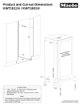
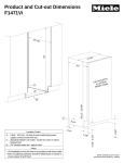
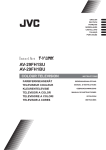
Fully Integrated
36” Bottom Mount
KF 1913 Vi / KF 1903 Vi
8mieleusa.com
Fully Integrated 36” Bottom Mount
KF 1913 Vi / KF 1903 Vi
FOR FLUSH INSTALLATION
25" m
84"
in.*
4"
35 3/
24 5/
8"
EPTS
ACC TOM
T
I
N
U
US
(2) C
S
TWO T PANEL
N
O
R
F
O
36"
83 1/2" - 85 3/8"
W
E
10 1/
1 1/8
Location Codes
E - 5 foot - 120 Volt - 15 Amp 3-wire molded plug power
supply connects lower left rear
O - Standard NEMA 5-15 Duplex Outlet - locate less than
9" above finished floor
W - 1/4" flexible water line - tape to floor
4 1/8
"
6 5/8" - 8 1/2"
"
2" - 8 3/8"
4"
Notes
• All Installations must be done in accordance with local codes
• Sides of adjoining cabinets should be filled (flush to frame) to
insure proper fit and finish
• For Proud Installation - please adjust accordingly
* Depth assumes a 3/4” panel, please adjust according to
custom panel thickness
KF 1913 Vi / KF 1903 Vi
Page 2 of 7
Fully Integrated 36” Bottom Mount
KF 1913 Vi / KF 1903 Vi
LOWER HINGE LOCATION
Hinge
FRONT VIEW
Upper Door
Hinge
1/2" - 2 3/8"
29 11/16"
29 1/8 - 29 1/2"
Lower Drawer
KF 1913 Vi / KF 1903 Vi
Page 3 of 7
Fully Integrated 36” Bottom Mount
KF 1913 Vi / KF 1903 Vi
CUSTOM PANEL INSTALLATIONS
These units do not come equipped with a front panel. They are designed to accept a custom door panel supplied by
the cabinet maker. Miele has a unique panel integration system which allows the panels to align with the surrounding
cabinets.
Panel size is determined in the following manner:
Width:
Thickness:
35 3/4" in all cases
Minumum 3/4" outside frame
Panel "B" Height
Upper Panel
Lower Panel
HOM
Panel Height
Standard Upper Panel Height: 53 5/16"
Notes: Finish back side of panels to insure appearance
Panel may extend above unit. This is not
considered in height calculation
Upper Maximum panel weight:
83.8 Pounds
Lower Panel Height: Use the following calculation:
Panel Height = HOM - 53 9/16 - TKH
HOM = Total height of machine. Can be adjusted to
match adjoining cabinets - typically 84"
HOM is adjustable between 83 1/2" - 85 3/8"
TKH = Toe-kick height (2" - 8 3/8")
TKH
Lower Maximum panel weight:
31 Pounds
Upper Panel Notes
If the adjoining cabinets are taller than the height of machine (HOM) - the upper panel may be extended accordingly.
Find the difference between height of the adjoining cabinets and the height of machine (HOM) and add to 53 5/16"
Adjoining cabinet
Extended Panel
Machine
Example:
Ajoining cabinet height:
Height of machine:
Difference:
87"
84"
3"
Extended panel height:
56 5/16"
KF 1913 Vi / KF 1903 Vi
Page 4 of 7
Fully Integrated 36” Bottom Mount
KF 1913 Vi / KF 1903 Vi
HINGING DETAILS
90° Door
115° Door
Thickness options
Thickness options
0-1/8"
0-1/8"
0-3/4"
1"
1-1/4"
1-1/2"
1-3/4"
0-3/4"
1"
1-1/4"
1-1/2"
1-3/4"
2"
Cabinet Front
Cabinet Front
1"
Fro
nt P
ane
l
0-3/4"
1-1/2"
1-1/4"
1"
1-1/4"
Front Panel
0-3/4"
1-1/2"
Door Swing
Door Swing
16 7/8"
MAX
38 11/16"
7/16"
NOTE: Additional space needed depending on
thickness of front panels and handle used
NOTE: Additional space needed depending on
thickness of front panels and handle used
KF 1913 Vi / KF 1903 Vi
Page 5 of 7
Fully Integrated 36” Bottom Mount
KF 1913 Vi / KF 1903 Vi
HINGING DETAILS
115° Door
Thickness options
0-1/8"
0-3/4"
1"
1-1/4"
1-1/2"
1-3/4"
Cabinet Front
13/8”(35mm)
11/6” (29.6mm)
17/24” (18mm)
1/4”(6.4mm)
25/8” (67mm)
21/3” (59mm)
21/24”(52mm) 3/4”
1
(44.5mm)
3”(76.2mm)
F
r
o
nt P
ane
l
0-3/4"
1"
1-1/4"
1-1/2"
Door Swing
16 7/8"
MAX
KF 1913 Vi / KF 1903 Vi
Page 6 of 7
Fully Integrated 36” Bottom Mount
KF 1913 Vi / KF 1903 Vi
HINGING DETAILS FOR INSTALLATION
WITH APPLIANCE/OBJECT ON HINGE
SIDE
90° Door
Thickness options
Thickness o
0-1/8"
7/16”
13/16” (11 mm)
(30mm)
1-1/4"
1-1/2"
1-3/4"
0-3/4"
1"
1-1/4"
1-1/2"
1-3/4"
2"
17/16”
(36.5mm)
111/16”
(43mm)
115/16”
(49.2mm)
Cabinet Front
1"
1-1/4"
Front Panel
0-3/4"
Handle or object that is
NOT flush with Cabinet
Front.
1-1/2"
Door Swing
Door Swi
16 7/8
MAX
38 11/16"
7/16"
**When installing hing side next to an appliance or object that is within range of the door panel, limit the
door opening angle to 90O. This is done by installing the banking pin as illustrated.Insert the banking
pin through the holes and drive in with a hammer.
KF 1913 Vi / KF 1903 Vi
Page 7 of 7