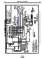
1
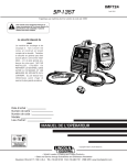
RETURN TO MAIN MENU
IM795
SP 170-I
March, 2004
For use with machine Code Numbers : 10982; 10983
Safety Depends on You
Lincoln arc welding and cutting
equipment is designed and built
with safety in mind. However, your
overall safety can be increased by
proper installation ... and thoughtful operation on your part. DO
NOT INSTALL, OPERATE OR
REPAIR THIS EQUIPMENT
WITHOUT READING THIS
MANUAL AND THE SAFETY
PRECAUTIONS CONTAINED
THROUGHOUT. And, most
importantly, think before you act
and be careful.
OPERATOR’S MANUAL
Copyright © 2004 Lincoln Global Inc.
• World's Leader in Welding and Cutting Products •
• Sales and Service through Subsidiaries and Distributors Worldwide •
Cleveland, Ohio 44117-1199 U.S.A. TEL: 216.481.8100 FAX: 216.486.1751 WEB SITE: www.lincolnelectric.com
i
i
SAFETY
WARNING
CALIFORNIA PROPOSITION 65 WARNINGS
Diesel engine exhaust and some of its constituents
are known to the State of California to cause cancer, birth defects, and other reproductive harm.
The Above For Diesel Engines
The engine exhaust from this product contains
chemicals known to the State of California to cause
cancer, birth defects, or other reproductive harm.
The Above For Gasoline Engines
ARC WELDING CAN BE HAZARDOUS. PROTECT YOURSELF AND OTHERS FROM POSSIBLE SERIOUS INJURY OR DEATH.
KEEP CHILDREN AWAY. PACEMAKER WEARERS SHOULD CONSULT WITH THEIR DOCTOR BEFORE OPERATING.
Read and understand the following safety highlights. For additional safety information, it is strongly recommended that you
purchase a copy of “Safety in Welding & Cutting - ANSI Standard Z49.1” from the American Welding Society, P.O. Box
351040, Miami, Florida 33135 or CSA Standard W117.2-1974. A Free copy of “Arc Welding Safety” booklet E205 is available
from the Lincoln Electric Company, 22801 St. Clair Avenue, Cleveland, Ohio 44117-1199.
BE SURE THAT ALL INSTALLATION, OPERATION, MAINTENANCE AND REPAIR PROCEDURES ARE
PERFORMED ONLY BY QUALIFIED INDIVIDUALS.
FOR ENGINE
powered equipment.
1.h. To avoid scalding, do not remove the
radiator pressure cap when the engine is
hot.
1.a. Turn the engine off before troubleshooting and maintenance
work unless the maintenance work requires it to be running.
____________________________________________________
1.b. Operate engines in open, well-ventilated
areas or vent the engine exhaust fumes
outdoors.
____________________________________________________
1.c. Do not add the fuel near an open flame
welding arc or when the engine is running.
Stop the engine and allow it to cool before
refueling to prevent spilled fuel from vaporizing on contact with hot engine parts and
igniting. Do not spill fuel when filling tank. If
fuel is spilled, wipe it up and do not start
engine until fumes have been eliminated.
____________________________________________________
1.d. Keep all equipment safety guards, covers and devices in
position and in good repair.Keep hands, hair, clothing and
tools away from V-belts, gears, fans and all other moving
parts when starting, operating or repairing equipment.
____________________________________________________
1.e. In some cases it may be necessary to remove safety
guards to perform required maintenance. Remove
guards only when necessary and replace them when the
maintenance requiring their removal is complete.
Always use the greatest care when working near moving
parts.
___________________________________________________
1.f. Do not put your hands near the engine fan.
Do not attempt to override the governor or
idler by pushing on the throttle control rods
while the engine is running.
ELECTRIC AND
MAGNETIC FIELDS
may be dangerous
2.a. Electric current flowing through any conductor causes
localized Electric and Magnetic Fields (EMF). Welding
current creates EMF fields around welding cables and
welding machines
2.b. EMF fields may interfere with some pacemakers, and
welders having a pacemaker should consult their physician
before welding.
2.c. Exposure to EMF fields in welding may have other health
effects which are now not known.
2.d. All welders should use the following procedures in order to
minimize exposure to EMF fields from the welding circuit:
2.d.1. Route the electrode and work cables together - Secure
them with tape when possible.
2.d.2. Never coil the electrode lead around your body.
2.d.3. Do not place your body between the electrode and
work cables. If the electrode cable is on your right
side, the work cable should also be on your right side.
2.d.4. Connect the work cable to the workpiece as close as
possible to the area being welded.
___________________________________________________
1.g. To prevent accidentally starting gasoline engines while
turning the engine or welding generator during maintenance
work, disconnect the spark plug wires, distributor cap or
magneto wire as appropriate.
2.d.5. Do not work next to welding power source.
Mar ‘95
ii
ii
SAFETY
ARC RAYS can burn.
ELECTRIC SHOCK can
kill.
3.a. The electrode and work (or ground) circuits
are electrically “hot” when the welder is on.
Do not touch these “hot” parts with your bare
skin or wet clothing. Wear dry, hole-free
gloves to insulate hands.
3.b. Insulate yourself from work and ground using dry insulation.
Make certain the insulation is large enough to cover your full
area of physical contact with work and ground.
In addition to the normal safety precautions, if welding
must be performed under electrically hazardous
conditions (in damp locations or while wearing wet
clothing; on metal structures such as floors, gratings or
scaffolds; when in cramped positions such as sitting,
kneeling or lying, if there is a high risk of unavoidable or
accidental contact with the workpiece or ground) use
the following equipment:
• Semiautomatic DC Constant Voltage (Wire) Welder.
• DC Manual (Stick) Welder.
• AC Welder with Reduced Voltage Control.
3.c. In semiautomatic or automatic wire welding, the electrode,
electrode reel, welding head, nozzle or semiautomatic
welding gun are also electrically “hot”.
3.d. Always be sure the work cable makes a good electrical
connection with the metal being welded. The connection
should be as close as possible to the area being welded.
3.e. Ground the work or metal to be welded to a good electrical
(earth) ground.
3.f. Maintain the electrode holder, work clamp, welding cable and
welding machine in good, safe operating condition. Replace
damaged insulation.
3.g. Never dip the electrode in water for cooling.
3.h. Never simultaneously touch electrically “hot” parts of
electrode holders connected to two welders because voltage
between the two can be the total of the open circuit voltage
of both welders.
3.i. When working above floor level, use a safety belt to protect
yourself from a fall should you get a shock.
3.j. Also see Items 6.c. and 8.
4.a. Use a shield with the proper filter and cover
plates to protect your eyes from sparks and
the rays of the arc when welding or observing
open arc welding. Headshield and filter lens
should conform to ANSI Z87. I standards.
4.b. Use suitable clothing made from durable flame-resistant
material to protect your skin and that of your helpers from
the arc rays.
4.c. Protect other nearby personnel with suitable, non-flammable
screening and/or warn them not to watch the arc nor expose
themselves to the arc rays or to hot spatter or metal.
FUMES AND GASES
can be dangerous.
5.a. Welding may produce fumes and gases
hazardous to health. Avoid breathing these
fumes and gases.When welding, keep
your head out of the fume. Use enough
ventilation and/or exhaust at the arc to keep
fumes and gases away from the breathing zone. When
welding with electrodes which require special
ventilation such as stainless or hard facing (see
instructions on container or MSDS) or on lead or
cadmium plated steel and other metals or coatings
which produce highly toxic fumes, keep exposure as
low as possible and below Threshold Limit Values (TLV)
using local exhaust or mechanical ventilation. In
confined spaces or in some circumstances, outdoors, a
respirator may be required. Additional precautions are
also required when welding on galvanized steel.
5.b. Do not weld in locations near chlorinated hydrocarbon vapors
coming from degreasing, cleaning or spraying operations.
The heat and rays of the arc can react with solvent vapors to
form phosgene, a highly toxic gas, and other irritating products.
5.c. Shielding gases used for arc welding can displace air and
cause injury or death. Always use enough ventilation,
especially in confined areas, to insure breathing air is safe.
5.d. Read and understand the manufacturer’s instructions for this
equipment and the consumables to be used, including the
material safety data sheet (MSDS) and follow your
employer’s safety practices. MSDS forms are available from
your welding distributor or from the manufacturer.
5.e. Also see item 1.b.
Mar ‘95
iii
iii
SAFETY
CYLINDER may explode
if damaged.
WELDING SPARKS can
cause fire or explosion.
6.a. Remove fire hazards from the welding area.
If this is not possible, cover them to prevent
the welding sparks from starting a fire.
Remember that welding sparks and hot
materials from welding can easily go through small cracks
and openings to adjacent areas. Avoid welding near
hydraulic lines. Have a fire extinguisher readily available.
6.b. Where compressed gases are to be used at the job site,
special precautions should be used to prevent hazardous
situations. Refer to “Safety in Welding and Cutting” (ANSI
Standard Z49.1) and the operating information for the
equipment being used.
6.c. When not welding, make certain no part of the electrode
circuit is touching the work or ground. Accidental contact
can cause overheating and create a fire hazard.
6.d. Do not heat, cut or weld tanks, drums or containers until the
proper steps have been taken to insure that such procedures
will not cause flammable or toxic vapors from substances
inside. They can cause an explosion even though they have
been “cleaned”. For information, purchase “Recommended
Safe Practices for the Preparation for Welding and Cutting of
Containers and Piping That Have Held Hazardous
Substances”, AWS F4.1 from the American Welding Society
(see address above).
6.e. Vent hollow castings or containers before heating, cutting or
welding. They may explode.
6.f. Sparks and spatter are thrown from the welding arc. Wear oil
free protective garments such as leather gloves, heavy shirt,
cuffless trousers, high shoes and a cap over your hair. Wear
ear plugs when welding out of position or in confined places.
Always wear safety glasses with side shields when in a
welding area.
6.g. Connect the work cable to the work as close to the welding
area as practical. Work cables connected to the building
framework or other locations away from the welding area
increase the possibility of the welding current passing
through lifting chains, crane cables or other alternate circuits. This can create fire hazards or overheat lifting chains
or cables until they fail.
6.h. Also see item 1.c.
7.a. Use only compressed gas cylinders
containing the correct shielding gas for the
process used and properly operating
regulators designed for the gas and
pressure used. All hoses, fittings, etc. should be suitable for
the application and maintained in good condition.
7.b. Always keep cylinders in an upright position securely
chained to an undercarriage or fixed support.
7.c. Cylinders should be located:
• Away from areas where they may be struck or subjected to
physical damage.
• A safe distance from arc welding or cutting operations and
any other source of heat, sparks, or flame.
7.d. Never allow the electrode, electrode holder or any other
electrically “hot” parts to touch a cylinder.
7.e. Keep your head and face away from the cylinder valve outlet
when opening the cylinder valve.
7.f. Valve protection caps should always be in place and hand
tight except when the cylinder is in use or connected for
use.
7.g. Read and follow the instructions on compressed gas
cylinders, associated equipment, and CGA publication P-l,
“Precautions for Safe Handling of Compressed Gases in
Cylinders,” available from the Compressed Gas Association
1235 Jefferson Davis Highway, Arlington, VA 22202.
FOR ELECTRICALLY
powered equipment.
8.a. Turn off input power using the disconnect
switch at the fuse box before working on
the equipment.
8.b. Install equipment in accordance with the U.S. National
Electrical Code, all local codes and the manufacturer’s
recommendations.
8.c. Ground the equipment in accordance with the U.S. National
Electrical Code and the manufacturer’s recommendations.
Mar ‘95
iv
iv
SAFETY
PRÉCAUTIONS DE SÛRETÉ
Pour votre propre protection lire et observer toutes les instructions
et les précautions de sûreté specifiques qui parraissent dans ce
manuel aussi bien que les précautions de sûreté générales suivantes:
Sûreté Pour Soudage A L’Arc
1. Protegez-vous contre la secousse électrique:
a. Les circuits à l’électrode et à la piéce sont sous tension
quand la machine à souder est en marche. Eviter toujours
tout contact entre les parties sous tension et la peau nue
ou les vétements mouillés. Porter des gants secs et sans
trous pour isoler les mains.
b. Faire trés attention de bien s’isoler de la masse quand on
soude dans des endroits humides, ou sur un plancher
metallique ou des grilles metalliques, principalement dans
les positions assis ou couché pour lesquelles une grande
partie du corps peut être en contact avec la masse.
c. Maintenir le porte-électrode, la pince de masse, le câble
de soudage et la machine à souder en bon et sûr état
defonctionnement.
d.Ne jamais plonger le porte-électrode dans l’eau pour le
refroidir.
e. Ne jamais toucher simultanément les parties sous tension
des porte-électrodes connectés à deux machines à souder
parce que la tension entre les deux pinces peut être le
total de la tension à vide des deux machines.
f. Si on utilise la machine à souder comme une source de
courant pour soudage semi-automatique, ces precautions
pour le porte-électrode s’applicuent aussi au pistolet de
soudage.
2. Dans le cas de travail au dessus du niveau du sol, se protéger
contre les chutes dans le cas ou on recoit un choc. Ne jamais
enrouler le câble-électrode autour de n’importe quelle partie
du corps.
3. Un coup d’arc peut être plus sévère qu’un coup de soliel,
donc:
a. Utiliser un bon masque avec un verre filtrant approprié
ainsi qu’un verre blanc afin de se protéger les yeux du rayonnement de l’arc et des projections quand on soude ou
quand on regarde l’arc.
b. Porter des vêtements convenables afin de protéger la
peau de soudeur et des aides contre le rayonnement de
l‘arc.
c. Protéger l’autre personnel travaillant à proximité au
soudage à l’aide d’écrans appropriés et non-inflammables.
4. Des gouttes de laitier en fusion sont émises de l’arc de
soudage. Se protéger avec des vêtements de protection libres
de l’huile, tels que les gants en cuir, chemise épaisse, pantalons sans revers, et chaussures montantes.
5. Toujours porter des lunettes de sécurité dans la zone de
soudage. Utiliser des lunettes avec écrans lateraux dans les
zones où l’on pique le laitier.
6. Eloigner les matériaux inflammables ou les recouvrir afin de
prévenir tout risque d’incendie dû aux étincelles.
7. Quand on ne soude pas, poser la pince à une endroit isolé de
la masse. Un court-circuit accidental peut provoquer un
échauffement et un risque d’incendie.
8. S’assurer que la masse est connectée le plus prés possible
de la zone de travail qu’il est pratique de le faire. Si on place
la masse sur la charpente de la construction ou d’autres
endroits éloignés de la zone de travail, on augmente le risque
de voir passer le courant de soudage par les chaines de levage, câbles de grue, ou autres circuits. Cela peut provoquer
des risques d’incendie ou d’echauffement des chaines et des
câbles jusqu’à ce qu’ils se rompent.
9. Assurer une ventilation suffisante dans la zone de soudage.
Ceci est particuliérement important pour le soudage de tôles
galvanisées plombées, ou cadmiées ou tout autre métal qui
produit des fumeés toxiques.
10. Ne pas souder en présence de vapeurs de chlore provenant
d’opérations de dégraissage, nettoyage ou pistolage. La
chaleur ou les rayons de l’arc peuvent réagir avec les vapeurs
du solvant pour produire du phosgéne (gas fortement toxique)
ou autres produits irritants.
11. Pour obtenir de plus amples renseignements sur la sûreté,
voir le code “Code for safety in welding and cutting” CSA
Standard W 117.2-1974.
PRÉCAUTIONS DE SÛRETÉ POUR
LES MACHINES À SOUDER À
TRANSFORMATEUR ET À
REDRESSEUR
1. Relier à la terre le chassis du poste conformement au code de
l’électricité et aux recommendations du fabricant. Le dispositif
de montage ou la piece à souder doit être branché à une
bonne mise à la terre.
2. Autant que possible, I’installation et l’entretien du poste seront
effectués par un électricien qualifié.
3. Avant de faires des travaux à l’interieur de poste, la debrancher à l’interrupteur à la boite de fusibles.
4. Garder tous les couvercles et dispositifs de sûreté à leur
place.
Mar. ‘93
v
SAFETY
v
vi
SAFETY
vi
vii
vii
Thank You
for selecting a QUALITY product by Lincoln Electric. We want you
to take pride in operating this Lincoln Electric Company product
••• as much pride as we have in bringing this product to you!
Please Examine Carton and Equipment For Damage Immediately
When this equipment is shipped, title passes to the purchaser upon receipt by the carrier. Consequently, Claims
for material damaged in shipment must be made by the purchaser against the transportation company at the
time the shipment is received.
Please record your equipment identification information below for future reference. This information can be
found on your machine nameplate.
Product _________________________________________________________________________________
Model Number ___________________________________________________________________________
Code Number or Date Code_________________________________________________________________
Serial Number____________________________________________________________________________
Date Purchased___________________________________________________________________________
Where Purchased_________________________________________________________________________
Whenever you request replacement parts or information on this equipment, always supply the information you
have recorded above. The code number is especially important when identifying the correct replacement parts.
On-Line Product Registration
- Register your machine with Lincoln Electric either via fax or over the Internet.
• For faxing: Complete the form on the back of the warranty statement included in the literature packet
accompanying this machine and fax the form per the instructions printed on it.
• For On-Line Registration: Go to our WEB SITE at www.lincolnelectric.com. Choose “Quick Links” and then
“Product Registration”. Please complete the form and submit your registration.
Read this Operators Manual completely before attempting to use this equipment. Save this manual and keep it
handy for quick reference. Pay particular attention to the safety instructions we have provided for your protection.
The level of seriousness to be applied to each is explained below:
WARNING
This statement appears where the information must be followed exactly to avoid serious personal injury or
loss of life.
CAUTION
This statement appears where the information must be followed to avoid minor personal injury or damage to
this equipment.
viii
viii
TABLE OF CONTENTS
Page
Installation .......................................................................................................Section A
Technical Specifications ........................................................................................A-1
Identify and Locate Components ...........................................................................A-2
Select Suitable Location ........................................................................................A-3
Output Connections ...............................................................................................A-3
Work Clamp Installation ..................................................................................A-3
Work Cable Installation ...................................................................................A-3
Gun Installation......................................................................................................A-4
Gas Connection .....................................................................................................A-4
Input Connections..................................................................................................A-5
Line Cord Connection ............................................................................................A-6
Operation .........................................................................................................Section B
Safety Precautions ................................................................................................B-1
General Description ...............................................................................................B-2
Design Features and Advantages .........................................................................B-2
Welding Capability .................................................................................................B-2
Limitations..............................................................................................................B-2
Controls and Settings ............................................................................................B-2
Welding Operations ...............................................................................................B-3
Wire Loading ...................................................................................................B-3
Wire Threading................................................................................................B-4
Making a Weld ................................................................................................B-5
Process Guidelines................................................................................................B-5
Chaning Over to Feed Other Wire Sizes ...............................................................B-6
Welding with GMAW..............................................................................................B-6
Welding with FCAW...............................................................................................B-6
Overload Protection ...............................................................................................B-6
Application Chart ...................................................................................................B-7
Accessories .....................................................................................................Section C
Accessories ...........................................................................................................C-1
Replacement Parts ................................................................................................C-2
Maintenance ....................................................................................................Section D
Safety Precautions ................................................................................................D-1
Routine Maintenance.............................................................................................D-1
Gun and Cable Maintenance.................................................................................D-2
Configuration of Components in Wire Feeding System.........................................D-2
Component Replacement Procedures ..................................................................D-2
Troubleshooting ..............................................................................................Section E
Safety Precautions.................................................................................................E-1
How to Use Troubleshooting Guide.......................................................................E-1
Troubleshooting Guide ..........................................................................................E-2
Wiring Diagrams ..............................................................................................Section F
SP 170-I Wiring Diagram .......................................................................................F-1
SP 170-I Parts...............................................................................................P467 Series
Wire Drive Assembly...........................................................................................P189-D
A-1
A-1
INSTALLATION
TECHNICAL SPECIFICATIONS – SP 170-I
INPUT – SINGLE PHASE ONLY
Standard Voltage/Frequency
230V/50/60Hz
Input Current
20 Amps – Rated Output
RATED OUTPUT
Duty Cycle
25%
60%
100%
Amps
125
85
70
Volts at Rated Amperes
20.25
18.25
17.50
OUTPUT
Welding Current Range
Rated DC Output: 30 – 175 amps
Maximum Open Circuit Voltage
33
Wire Speed Range
50-400IPM (1.3-10.2m/min)
RECOMMENDED INPUT CABLE AND FUSE SIZES
Output Mode
Input Voltage
Fuse or
Breaker Size
Input Amps
Power Cord
RATED
230V/50/60Hz
30 Super Lag
20
16 Amp, 230V,
Two-Prong International
Cord Set (Supplied)
PHYSICAL DIMENSIONS
Height
12.0 in
305 mm
Width
9.75 in
248 mm
Depth
16.5 in
419 mm
The SP170-I is designed for industrial and professional use
in accordance with the standard EN 60974-1 / IEC 974-1.
SP-170-I
Weight
57 Ibs
25.9 kg
A-2
A-2
INSTALLATION
Read entire installation section before starting
installation.
1
SAFETY PRECAUTIONS
2
E
WARNING
WELDI
NG AM
P RA
NGE
SP 1
70 -I
ELECTRIC SHOCK can kill.
• Only qualified personnel should perform
this installation.
• Only personnel that have read and understood the SP 170-I Operating Manual
should install and operate this equipment.
• Machine must be plugged into a receptacle
which is grounded per any national, local
or other applicable electrical codes.
4
• The SP 170-I power switch is to be in the
OFF (“O”) position when installing work
cable and gun and when connecting power
cord to input power.
3
8
6
IDENTIFY AND LOCATE
COMPONENTS
5
If you have not already done so, unpack the SP 170-I
from its carton and remove all packing material
around the SP 170-I. Remove the following loose
items from the carton (see Figure A.1):
1. SP 170-I
2. Gun and cable assembly(1)
3. Literature and miscellaneous including:
a) This operating manual
b) Contact tips:
SP 170-I
2
.025” (0.6mm) for solid wire
2
.030” (0.8mm) for solid wire
1
.035” (0.9mm) for cored wire
c) 5/64” (2.0 mm) Hex key wrench for removal of
drive roll.
4. 10 ft (3,0 m) work cable.
5. Work clamp.
6. 14.0 ft (4.3 m) .19” (4.8 mm) dia. gas hose
7. 2- Hose clamps
8. Gas nozzle
(1)
The gun is ready to feed .035" (0.9mm) diameter.
SP 170-I
7
FIGURE A.1
A-3
A-3
INSTALLATION
SELECT SUITABLE LOCATION
3. Connector Block.
The SP 170-I has an IP21S rating. Locate the welder
in a dry location where there is free circulation of clean
air into the louvers in the back and out the front of the
unit. A location that minimizes the amount of smoke
and dirt drawn into the rear louvers reduces the
chance of dirt accumulation that can block air passages and cause overheating.
4. Gun Trigger Lead Connectors.
5. Positive (+) and negative (–) output terminals.
6. Wire Feed Gearbox / Feedplate
7. Cable Hanger.
8. Thumbscrew.
STACKING
SP 170-I’s cannot be stacked.
Refer to the Accessories Section for available optional
TILTING
equipment.
Each machine must be placed on a secure, level surface, either directly or on the recommended cart. The
machine may topple over if this procedure is not followed.
Work Clamp Installation
Attach the work clamp per the following: Refer to
Figure A-3
FIGURE A.3
LIMITATIONS
STRAIN RELIEF HOLE
WORK CABLE
The SP 170-I cannot be used for pipe thawing.
NUT AND BOLT
MIG welding and flux cored arc welding are the only
processes supported by the SP 170-I
WORK CLAMP
The handle can not be used for transport by crane.
OUTPUT CONNECTIONS
1. Insert the work cable terminal lug with the larger
hole through the strain relief hole in the work clamp
as shown above.
Refer to Figure A.2.
1. Work Cable Access Hole.
2. Fasten securely with the bolt and nut provided.
2. Gun Cable and Control Lead Access Hole.
4
E
5
+
SP 170 - I
1
8
2
-
3
FIGURE A.2
SP 170-I
6
7
A-4
A-4
INSTALLATION
Work Cable Installation
Connecting Gun Cable to the SP 170-I
Refer to Figure A.2.
As shipped the gun is fitted with a liner suitable for all
wire diameters from .025” - .035” (0.6mm - .9mm) and
has an .035” (0.9mm) contact tip installed.
1. Open the wire feed section door on the right side of
the SP 170-I.
2. Pass the end of the work cable that has the terminal lug with the smaller hole through the Work
Cable Access Hole (1) in the case front.
3. Route the cable under the feedplate (6) and in front
of the Wire Feed Motor.
4. For Innershield Only: Refer to Figure A.2. As
delivered, the machine is connected for negative
electrode polarity. This is the appropriate configuration for the Innershield process. To complete
installation, use the provided wing nut to connect
the work cable’s terminal lug to the positive (+) output terminal (4) located above the Wire Feed
Gearbox (5). Make sure that both wing nuts are
tight.
5. For GMAW Only: Refer to Figure A.4. To wire for
positive polarity (required for the GMAW process),
connect the short cable attached to the connector
block (1) to the positive (+) output terminal (4) and
the work cable (3) to the negative (-) terminal (2).
1. Refer to Figures A.2 and A.4. Unplug the machine
or turn power switch to the OFF “O” position.
2. Pass the insulated terminals of the gun trigger control leads, one at a time, through the Gun Cable
and Control Lead Access Slot (A.2-2) in the case
front. The leads are to be routed up the inside of
the case front, behind the gas line.
3. Insert the connector on the gun conductor cable
through the Gun Cable Access Hole (A.2-2) in the
SP 170-I case front. Make sure the connector is all
the way in the brass connector block to obtain
proper gas flow. If the gun connector will not fully
insert, unscrew the thumbscrew on the connector
block a few turns. Rotate the connector so control
leads are on the underside and tighten the
Thumbscrew on the connector block.
4. Connect the gun trigger control lead terminals to
the two insulated 1/4" (6,4 mm) tab terminal connector bushings located above the “Gun Trigger
Connection” decal in the wire feed section (A.4).
Either lead can go to either connector.
CAUTION
4
If the gun trigger switch being used is other than
that supplied, the switch must be a normally open,
momentary switch. The terminals of the switch
must be insulated from the welding circuit.
Malfunction of the SP 170-I may result if this
switch shorts to the SP 170-I welding output circuit or is common to any electrical circuit other
than the SP 170-I trigger circuit.
3
2
1
5
GAS CONNECTION
When using the MIG process, a cylinder of shielding
gas must be obtained. See Table B.1. Additionally a
flow regulator is required. For more information, refer
to the ACCESSORIES section.
FIGURE A.4
GUN INSTALLATION
As shipped from the factory, the SP 170-I gun is ready
to feed .035 Innershield. If other wire is to be used,
change the contact tip to the appropriate size.
SP 170-I
A-5
A-5
INSTALLATION
let and open the cylinder valve very slightly for an
instant. This blows away any dust or dirt which may
have accumulated in the valve outlet.
WARNING
CYLINDER may explode if damaged. Keep cylinder upright and
chained to support
WARNING
• Keep cylinder away from areas
where it may be damaged.
BE SURE TO KEEP YOUR FACE AWAY FROM THE
VALVE OUTLET WHEN “CRACKING” THE VALVE.
Never stand directly in front of or behind the flow
regulator when opening the cylinder valve. Always
stand to one side.
• Never lift welder with cylinder
attached.
• Never allow welding electrode to
touch cylinder.
• Keep cylinder away from welding
or other live electrical circuits.
3. Attach the flow regulator to the cylinder valve and
tighten the union nut securely with a wrench..
NOTE: If connecting to 100% CO2 cylinder, make
certain the plastic washer is seated in the fitting
that attaches to the CO2 cylinder.
WARNING
BUILDUP OF SHIELDING GAS may
harm health or kill.
• Shut off shielding gas supply
when not in use.
• SEE AMERICAN NATIONAL
STANDARD Z-49.1, “SAFETY IN
WELDING AND CUTTING” PUBLISHED BY THE AMERICAN
WELDING SOCIETY.
4. Refer to Figure A.6. Attach one end of inlet gas
hose to the outlet fitting of the flow regulator and
tighten the gas line hose clamp. Connect the other
end to the SP 170-I Gas Solenoid Inlet nipple.
Make certain the gas hose is not kinked or twisted.
Tighten the gas line hose clamp.
INPUT CONNECTIONS
Refer to Figure A.6.
1. Chain the cylinder to a wall or other stationary support to prevent the cylinder from falling over.
Insulate the cylinder from the work circuit and earth
ground. Refer to Figure A.5.
Cylinder Valve
Flow Regulator
GAS SOLENOID
INLET NIPPLE
Gas Hose
POWER INPUT
CABLE
FIGURE A.6
FIGURE A.5
2. With the cylinder securely installed, remove the
cylinder cap. Stand to one side away from the outSP 170-I
A-6
INSTALLATION
Line Cord Connection
A 3 conductor international cordset with a 16 amp,
230 volt, two-prong plug is factory installed. Connect
this plug to a mating grounded receptacle which is
connected to an appropriate power supply per any
applicable local codes.
Input
Voltage
Hertz
Type 75°C
Wire in Conduit,
Copper Cond.
AWG Size
230
50/60
8
Grounding
Wire
Copper
Cond.
AWG Size
Fuse
Size
(Super
Lag)
10
40
CONNECT TO A SYSTEM
GROUNDING WIRE. SEE
THE UNITED STATES
NATIONAL ELECTRICAL
CODE AND/OR LOCAL
CODES FOR OTHER
DETAILS AND MEANS FOR
PROPER GROUNDING.
CONNECT TO HOT WIRES
OF A THREE-WIRE SINGLE
PHASE SYSTEM OR TO
ONE PHASE OF A TWO OR
THREE PHASE SYSTEM.
WARNING
This welding machine must be connected to a
power source in accordance with applicable electrical codes.
The National Electrical Code provides standards
for amperage handling capability of supply conductors based on duty cycle of the welding
source.
If there is any question about the installation
meeting applicable electrical code requirements,
consult a qualified electrician.
SP 170-I
A-6
B-1
OPERATION
B-1
GENERAL DESCRIPTION
Read entire operation section before
operating the SP 170-I.
The SP 170-I is a complete semiautomatic constant
voltage DC portable arc welder. Included is a tapswitch controlled, single phase constant voltage transformer/rectifier power source and a wire feeder with
welding gun for feeding .025" (0.6 mm) through .030"
(0.8 mm) solid steel electrode and .035" (0.9 mm)
Innershield® NR-211-MP.
WARNING
ELECTRIC SHOCK can kill.
• Do not touch electrically live
parts or electrode with skin or
wet clothing. Insulate yourself
from work and ground.
It is ideally suited for individuals having access to
230V 50/60 Hz AC input power and want the ease of
use, quality and dependability of both gas metal arc
welding or GMAW (also known as MIG welding) and
the Innershield® process (self-shielded flux-cored or
FCAW). A convenient chart is mounted inside the wire
feed section door for setting welding procedures for 24
gauge (.60 mm) through 5/16" (8.0 mm) mild steel.
The machine is rugged and reliable and is designed
for dependable service and long life.
• Always wear dry insulating
gloves.
FUMES AND GASES can be
dangerous.
• Keep your head out of fumes.
• Use ventilation or exhaust to
remove fumes from breathing
zone.
RECOMMENDED PROCESSES
The SP 170-I can be used for welding mild steel,
stainless steels and aluminum using the GMAW, single pass, process (MIG) which requires a supply of
shielding gas or it can be used for the self-shielded,
Innershield® process (FCAW).
WELDING SPARKS can
cause fire or explosion.
• Keep flammable material away.
• Do not weld on closed containers.
OPERATIONAL FEATURES AND
CONTROLS
The SP 170-I has the following controls as standard:
Power ON/OFF Switch, Voltage Control, Wire Speed
Control, Trigger Switch, and a Circuit Breaker.
ARC RAYS can burn eyes
and skin.
DESIGN FEATURES AND
ADVANTAGES
• Wear eye, ear and body protection.
● “Cold electrode” until gun trigger is pressed for an
added measure of safety.
● Overload protection — incorporates both a thermo-
stat and a circuit breaker.
Observe all safety information throughout
this manual.
● Quality wire drive with electronic overload protec-
tion.
● “Quick Release” idle roll pressure arm is easily
adjusted.
● Reversible, dual groove drive roll, shipped ready
to feed .030" (0.8 mm) diameter solid wire or .035"
diameter flux-cored wire. The drive roll is easily
reversed to feed .025" (0.6 mm) diameter solid
wire.
●
SP-170-I
B-2
OPERATION
B-2
● No external shielding gas is required when used
6. Gun Trigger - Activates welding output, wire feed,
with Lincoln Innershield .035” (0,9 mm) NR®-211MP electrode.
and gas solenoid operation. Releasing the trigger
deactivates welding and simultaneously activates
the “burnback” function so that the welding wire
does not stick in the weld puddle.
● Spindle accommodates both 8 in. (200 mm) diame-
ter and 4 in. (100 mm) diameter spools of wire.
FIGURE B.1a
WELDING CAPABILITY
The SP 170-I is rated at 125 amps, 20.25 volts, at
25% duty cycle on a ten minute basis. It is capable of
higher output currents at lower duty cycles. Actual
welding outputs will range between 30 and 175 amps
for the recommended processes.
1
LIMITATIONS
2
3
4
E
Arc Gouging cannot be performed with the SP 170-I.
The SP 170-I is not recommended for pipe thawing or
TIG welding.
SP 170 - I
CONTROLS AND SETTINGS
Refer to Figures B.1a
(Items 1 thru 4)
1. Power ON/OFF Switch — When
the power is on the fan motor
will run and air will be exhausted out the louvers in the front of
the machine. The welding output and wire feeder remain off
until the gun trigger is pressed.
2. Voltage Control — A 5-position
tap selector switch gives full
range adjustment of power
source output voltage. Do not
switch while welding.
3. Wire Speed Control — Controls
the wire feed speed from 50 –
400 in/min (1.3 – 10.2 m/min).
The control can be preset on
the dial to the setting specified
on the SP 170-I Application
Chart located on the inside of
the wire feed section door.
FIGURE B.1b
5
ON
OFF
ARC VOLTS
6
WIRE SPEED
4. Temperature Light — Indicates
thermostat has cut the output.
The fan will be running.
Thermostat resets automatically.
(Refer to Figure B.1b, Items 5,6)
5. Circuit Breaker – Protects machine from damage if
maximum output is exceeded. Button will extend
out when tripped (Manual reset).
SP 170-I
B-3
B-3
OPERATION
WELDING OPERATIONS
SEQUENCE OF OPERATION
Wire Loading
Refer to Figures B.2 and B.3.
4" Wire Spool
Wire Spindle Shaft
The machine power switch should be turned to the
OFF (“O”) position before working inside the wire feed
enclosure.
The welder is shipped from the factory ready to feed
8" (200 mm) diameter spools with 2.2" (56 mm) maximum width. These spools fit on a 2" (51 mm) diameter
spindle that has a built in, adjustable friction brake to
prevent overrun of the spool and excess slack in the
wire.
Note:When loading and removing the 8” Spools make
sure that the wing nut (inside the wire spool spindle
hub) is turned 90° from the wire spool spindle locking
tab. If the wing nut is positioned in line with the locking
tab, the tab cannot be depressed to load or unload the
wire spool.
FIGURE B.2
Wire Spool Spindle
8” Wire Spool
Wing Nut
and Spacer
To Wire Drive
FIGURE B.3
Friction Brake Adjustment
With wire spool installed on the spindle shaft and the
wing nut loose, turn the spool by hand while slowly
tightening the wing nut until a light drag is felt. Tighten
the wing nut an additional 1/4 turn.
Note: When properly adjusted, the brake should provide only enough drag to prevent overrun of the spool
and excess slack in the wire. Too much drag may
result in wire feeding problems, and may cause premature wear of wire drive system components.
Be sure that this stud engages
the hole in the wire spool.
To Wire Drive
Wire Spool must be pushed all the way on the spindle so that the
spindle’s tab will hold it in place. The Wire Spool will rotate clockwise when wire is dereeled.
Load an 8” (200 mm) diameter spool on the wire spool
spindle shown in Figure B.2.
To use 4” (100 mm) diameter spools, the 2” (50 mm)
diameter spindle must be removed (See Figure B.3).
Remove the wing nut and spacer at the end of the
shaft and remove the outside plastic wire spool spindle. The spindle can be stored in the wire feed compartment. A 4” (100 mm) diameter spool is mounted
directly on the 5/8” (16 mm) diameter shaft and held in
place with the previously removed hardware. Also
make certain the start end of the wire, which may protrude through the side of the spool does not contact
any metallic case parts.
SP 170-I
B-4
B-4
OPERATION
Refer to Figure B.4
1. Release the Spring Loaded Pressure Arm (1)
rotate the Idle Roll Arm (2) away from the Wire
Feed Drive Roll (3). Ensure that the groove size
in the feeding position on the drive roll matches the wire size being used. This occurs when
the desired groove is located on the inside, toward
the feedplate. See Maintenance section for further
information.
2
1
4
5
3
2. Carefully detach the end of the wire from the
spool. To prevent the spool from unwinding, maintain tension on the wire until after step 5.
The Wire Drive Feed Roll can
accommodate two wire sizes by
flipping the wire drive feed roll
over.
3. Cut the bent portion of wire off and straighten the
first 4” (100 mm).
FIGURE B.4
4. Thread the wire through the ingoing guide tube
(4), over the drive roll (3), and into the outgoing
guide tube (5). Check the alignment of the wire
over the drive roll groove and adjust if necessary.
If alignment adjustment is necessary use the allen
wrench provided to loosen the drive roll, move it to
the desired position and then retighten.
Gun Handle
Gas Diffuser
5. Close the idle roll arm (2) and latch the spring
loaded pressure arm (1) in place. Rotate the spool
counterclockwise if required to take up extra slack
in the wire.
Contact Tip
Gas Nozzle
6. The idle roll pressure adjustment wing nut is factory
set to approximately five full turns from where the
wing nut first engages the threads of the pressure
arm (1). If feeding problems occur because the wire
is flattened excessively, turn the pressure adjustment counter-clockwise to reduce distortion of the
wire. Slightly less pressure may be required when
using 0.023 – 0.025" (0,6 mm) wire. If the drive roll
slips while feeding wire, the pressure should be
increased until the wire feeds properly.
WARNING
When inching the welding wire, the drive rolls, the
gun connector block and the gun contact tip are
electrically energized relative to work and ground
and remain energized for several seconds after
the gun trigger is released.
FIGURE B.5
7. Refer to Figure B.5. Remove gas nozzle and contact tip from end of gun.
8. Turn the SP 170-I ON (“I”).
9. Straighten the gun cable assembly.
10. Depress the gun trigger switch and feed welding
wire through the gun and cable. (Point gun away
from yourself and others while feeding wire.)
Release gun trigger after wire appears at end of
gun.
11. Turn the SP 170-I OFF (“O”).
12. Replace contact tip and gas nozzle.
13. Refer to Figure B-6. Cut the wire off 3/8” – 1/2” (10
– 12 mm) from the end of the tip. The SP 170-I is
now ready to weld.
SP 170-I
B-5
B-5
OPERATION
Contact Tip
SP-170 -I
GUN CABLE
Wire Electrode
3/8" – 1/2" (10 - 12 mm)Contact
Tip To Work Distance(CTWD)
WORKPIECE
ARC
FIGURE B.6
WORK CLAMP
Making A Weld
1. See “Process Guidelines” in this section for selection of welding wire and shielding gas and for
range of metal thicknesses that can be welded.
2. See the Application chart on the inside of the wire
feed compartment door for information on setting
the SP 170-I controls. Refer to Table B.1 for aluminum and stainless wire.
3. Set the Voltage (“V”) and Wire Speed (“olo’”) controls to the settings suggested for the welding wire
and base metal thickness being used, refer to
3. Applications chart on the inside of the wire drive
compartment door.
4. Check that the polarity is correct for the welding
wire being used and that the gas supply, if
required, is turned on.
5. When using Innershield electrode, remove the gas
nozzle and install a gasless nozzle. This will
improve visibility of the arc and protect the gas diffuser from weld spatter. Refer to the MAINTENANCE section for details on nozzle replacement.
6. Refer to Figure B.7. Connect work clamp to metal
to be welded. Work clamp must make good electrical contact to the workpiece. The workpiece
must also be grounded as stated in “Arc Welding
Safety Precautions” in the beginning of this manual.
7. Position gun over joint. End of wire may be lightly
touching the work.
8. Lower welding helmet, close gun trigger, and
begin welding. Hold the gun so the contact tip to
work distance is about 3/8 inch (10 mm).
9. To stop welding, release the gun trigger and then
pull the gun away from the work after the arc goes
out.
FIGURE B.7
10. When no more welding is to be done, close valve
on gas cylinder (if used), momentarily operate gun
trigger to release gas pressure, and turn off the
SP 170-I.
Cleaning Tip And Nozzle
Clean the contact tip and nozzle to avoid arc bridging
between the nozzle and contact tip which can result in
a shorted nozzle, poor welds and an overheated gun.
Hint: Anti-stick spray or gel, available from a welding
supply distributor, may reduce buildup and aid in spatter removal.
PROCESS GUIDELINES
The SP 170-I can be used for welding mild steel,
stainless steel and aluminum using the MIG process
and also for welding mild steel with the gasless selfshielded, Innershield® process (FCAW).
The recommended gases and electrodes for MIG
(GMAW) are welding grade CO2 gas or an argon-CO2
blended gas (75 to 80% argon and 25 to 20% CO2)
and .025" (0.6 mm) and .030” (0.8mm) diameter
Lincoln L-56 mild-steel welding wire, supplied on 121/2 lb (5.7 kg) spools. The blended gas is recommended for welding on heavier steel, 14 gauge (2.0
mm), for example.
The recommended electrode for the self-shielded
process is Lincoln Innershield® NR-211-MP on 10 lb
(4.5 kg) spools. This electrode is available as .035"
(0.9 mm) and .045" (1.2 mm) NR-211-MP for all position welding of 18 gauge (1.2 mm) through 5/16" (8.0
mm) steel. Thickness of 1/4" (6.4 mm) and 5/16" (7.9
mm) require multiple passes. both wire sizes can also
be used for the welding of galvanized coated sheet
metal.
SP 170-I
B-6
OPERATION
The SP 170-I is suitable for .035" (0.9 mm) aluminum
wire and .023"– .035" (0.6 - 0.9 mm) stainless wire.
Refer to Table B.1 for Recommended Procedure
Settings. Aluminum wire requires an Aluminum
Welding kit. See ACCESSORIES section.
3. Keep the cylinder valve closed, except when using
the SP 170-I. When finished welding:
a) Close the cylinder valve to stop gas flow.
b) Depress the gun trigger briefly to release the
pressure in the gas hose.
CAUTION
c) Turn off the SP 170-I.
It is important when changing between welding
with steel wire and aluminum to exchange feeding
components due to the lubricant applied to steel
wire. Failure to do so may result in contaminated
welds when welding aluminum.
-----------------------------------------------------------------------TABLE B.1 — SP 170-I
WELDING PROCEDURES
Process Welding Wire
Shielding
Gas
Voltage/Wire Speed
22 ga 16 ga 12 ga 1/8” 3/16” 1/4”
.035 Dia(0.9mm 100% Argon B-5
B-7 E-9
G-9 I-9
4043 Aluminum
Wire
16 ga 14 ga 12 ga 10 ga
MIG DC+
.030 Dia
98% Argon/ A-3 C-6
308L Stainless 2% Oxygen
Steel Wire
B-6
J-10*
WELDING WITH FCAW (Innershield)
When using the FCAW process, the correct drive roll
and electrode polarity must be used. See Work Cable
Installation in INSTALLATION section for changing the
polarity.
Innershield welding kits K549-1 (for .035") and K549-2
(for .045") are also available.
D-7.5 D-7.5
OVERLOAD PROTECTION
CHANGING MACHINE OVER TO
FEED OTHER WIRE SIZES
The SP 170-I is shipped from the factory ready to feed
0.035" (0.9 mm) Innershield diameter wire. To operate
the SP 170-I with other sizes of wire, it maybe necessary to change the contact tip and change the drive
roll over to other sizes. Refer to Changing the Contact
Tip and Changing the Drive Roll, in the MAINTENANCE section, for specific information on these procedures.
WELDING WITH GMAW (MIG)
Shielding Gas
When using the GMAW process, obtain and install a
gas regulator and hose kit. If using 100% CO2 a CO2
adapter is required, sold separately.
Output Overload
The SP 170-I is equipped with a circuit breaker which
protects the machine from damage if a severe overload occurs. The circuit breaker button will extend out
when tripped. The circuit breaker must be manually
reset.
Thermal Protection
The SP 170-I has a rated output duty cycle of 20%. If
the duty cycle is exceeded, a thermal protector will
shut off the output until the machine cools to a reasonable operating temperature. This is an automatic function of the SP 170-I and does not require user intervention. The fan continues to run during cooling.
Electronic Wire Drive Motor Protection
The SP 170-I has built-in protection for wire drive
motor overload.
1. For CO2, open the cylinder very slowly. For argonmixed gas, open cylinder valve slowly a fraction of
a turn. When the cylinder pressure gauge pointer
stops moving, open the valve fully.
2. If using a regulator with an adjustable flow meter,
close the gun trigger and adjust the flow to give 15
– 20 cubic ft per hour (CFH) (7 – 10 I/min) [use 20
– 25 CFH (10 – 12 I/min) when welding out of
position or in a drafty location.
SP 170-I
.045 in. (1.2 mm) DIA.
INNERSHIELD
NR®-211-MP
.035 in. (0.9 mm) DIA.
INNERSHIELD
NR®-211-MP
.030 in. (0.8 mm) DIA.
SOLID STEEL WIRE
.025 in. (0.6 mm) DIA.
SOLID STEEL WIRE
WELDING WIRE
SP-170-I
GASLESS
FLUX-CORED
DC(-)
MIG
DC(+)
NONE
NONE
(7 5 -8 0 % A rg o n ,
2 5 -2 0 % C O 2 )
C20 or C25
CO2
(7 5 -8 0 % A rg o n ,
2 5 -2 0 % C O 2 )
C20 or C25
CO2
SHIELDING
GAS
OUTPUT POLARITY
GASLESS
FLUX-CORED
DC(-)
MIG
DC(+)
PROCESS
B-1
A-1
C-3
C-3
B-4
C-3
.060 in.
1.6 mm
B-1
B-2
D-5
D-4
C-5
D-5
.075 in.
2.0 mm
STEEL THICKNESS
C-1.5
B-2
E-8
E-6.5
D-6
E-7.5
.105 in.
2.5 mm
C-1.5
C-2.5
E-8
.135 in.
3.5 mm
DRIVE ROLL ORIENTATION
A-1
A-1
B-3
C-3
B-2
B-3
B-3
C-3
.048 in.
1.2 mm
A-2
B-2
.036 in.
1.0 mm
D-2
D-2.5
3/16 in.
5.0 mm
LARGE
GROOVE
SMALL
GROOVE
(BEVEL SIDE)
EITHER
GROOVE
Optional knurled drive roll for .035 and .045 wire
included in the .045 (1.2 mm) Innershield Kit.
EITHER
GROOVE
.045 (1.2 mm) DIA.
INNERSHIELD NR®-211-MP
.035/.045 liner and appropriate tip must be installed in gun - see manual.
LARGE
GROOVE
-- OR --
.035 (0.9 mm) DIA.
INNERSHIELD NR®-211-MP
GASLESS FLUX-CORED DC(-)
APPLICATION CHART
Be sure to read and understand the warnings on this welding machine and the section on ARC WELDING SAFETY PRECAUTIONS in
the Operating Manual. Because design, fabrication, assembly and welding variables affect the results obtained in applying this type
of information, the serviceability of a product or assembly is the responsibility of the builder/user.
.030 (0.8 mm) DIA.
SOLID STEEL WIRE
.025 (0.6 mm) DIA.
SOLID STEEL WIRE
MIG DC(+)
E-2.5*
D-2.5*
5/16
8.0 mm
* Multiple passes required
E-2*
D-2.5*
1/4 in.
6.0 mm
ALIGN GROOVE WITH CENTER OF GUIDE TUBES, SECURE DRIVE ROLL WITH SET SCREW CENTERED ON FLAT
A-2
B-2
B-2
A-2
.030 in.
0.80 mm
.024 in.
0.60 mm
ADJUST FOR OPTIMUM WELDING
FOR STAINLESS STEEL AND ALUMINUM SETTINGS - SEE MANUAL
SUGGESTED SETTINGS FOR WELDING
B-7
B-7
L10732 SP170-I
C-1
ACCESSORIES
OPTIONAL ACCESSORIES
See Maintenance section for instructions on
installing drive roll, cable liner, contact tip and their
proper configuration.
1. KP665-045C Drive Roll – Optional — Knurled
drive roll for feeding .035 - .045” (0.9 - 1.2 mm)
diameter flux-cored electrode.
C-1
3. K464 .035" (0.9 mm) Innershield® Welding Kit
— Includes a contact tip, a gasless nozzle and a
.035/.045" (0.9/1.2 mm) cable liner to permit the
gun and cable to use .035" (0.9 mm) diameter fluxcored electrode. The fitting on the end of the liner
is stenciled with the maximum rated wire size
(.045"/1.2 mm). Also included is a 10 lb.(4.5 kg.)
spool of .035" (0.9 mm) Innershield® NR-211-MP.
For use with “Lincoln Electric®” gun (with black
trigger). The end of the brass fitting on the end of
the .035/.045” (0.9/1.2mm) liner is color coded
green. (The .023-.030” (0.6-0.8mm) liner is color
coded orange).
2. K520 Utility Cart — Designed to transport the
Lincoln family of small welders. Has provisions for
mounting a single gas cylinder. Has front casters
and large rear wheels. Handle height is easily
adjustable. Bottom tray provided for tools and
accessories. Easy assembly required; takes less
than 15 minutes.
See “Innershield (FCAW) Conversion” in this section for installation instructions and MAINTENANCE section for proper feeding component configuration and installation.
4. K491 .045" (1.2 mm) Innershield® Welding Kit
— Includes a contact tip, a gasless nozzle and a
.035/.045" (0.9/1.2 mm) cable liner to permit the
gun and cable to use .045" (1.2 mm) diameter fluxcored electrode. The fitting on the end of the liner
is stenciled with the maximum rated wire size
(.045"/1.2 mm). Also included is a 10 lb.(4.5 kg.)
spool of .045" (1.2 mm) Innershield® NR-211-MP
and a knurled drive roll for .035” (0.9mm) and .045”
(1.2mm) wire.
For use with “Lincoln Electric®” gun (with black
trigger). The end of the brass fitting on the end of
the .035/.045” (0.9/1.2mm) liner is color coded
green. (The .023-.030” (0.6-0.8mm) liner is color
coded orange).
See “Innershield (FCAW) Conversion” in this section for installation instructions and MAINTENANCE section for proper feeding component configuration and installation.
SP-170-I
C-2
ACCESSORIES
MIG (GMAW)
CONVERSION
C-2
REPLACEMENT PARTS
Several changes are needed to convert the unit for
operation with the MIG (GMAW) process. The following conversions should be reviewed before welding
with (GMAW):
Complete Gun and Cable Assembly (Code 10983)
L11951
Complete Gun and Cable Assembly (Code 10982)
L8311-5
1. Change the output polarity to DC(+). See “Work
Cable Installation” in Installation section for details.
2. Install proper drive roll for the wire size selected.
See “Changing Drive Roll” in Maintenance section
for details.
3. Install the proper gun liner and tip for the wire size
selected. See “Component Replacement” in
Maintenance section for details.
4. Remove gasless nozzle (if installed) and install gas
nozzle.
5. Load wire into machine and thread into gun and
cable per “Welding Wire Loading” section.
SP 170-I
D-1
MAINTENANCE
MAINTENANCE
SAFETY PRECAUTIONS
WARNING
ELECTRIC SHOCK can kill.
• Disconnect input power by removing plug
from receptacle before working inside
SP170-I. Use only grounded receptacle. Do
not touch electrically “hot” parts inside
SP 170-I.
• Have qualified personnel do the maintenance and trouble shooting work.
ROUTINE MAINTENANCE
POWER SOURCE COMPARTMENT
In extremely dusty locations, dirt may clog the air passages
causing the welder to run hot. Blow dirt out of the welder with
low pressure air at regular intervals to eliminate excessive dirt
and dust build-up on interval parts.
WIRE FEED COMPARTMENT
1. When necessary, vacuum accumulated dirt from gearbox and
wire feed section.
2. Occasionally inspect the incoming guide tube and clean
inside diameter if necessary.
3. Motor and gearbox have lifetime lubrication and require no
maintenance.
FAN MOTOR
Has lifetime lubrication — requires no maintenance.
WIRE REEL SPINDLE
Requires no maintenance. Do not lubricate shaft.
SP 170-I
D-1
D-2
D-2
MAINTENANCE
GUN AND CABLE
MAINTENANCE
Gun Cable Cleaning
Clean cable liner after using approximately 300 lbs
(136 kg) of solid wire or 50 lbs (23 kg) of flux-cored
wire. Remove the cable from the wire feeder and lay it
out straight on the floor. Remove the contact tip from
the gun. Using low pressure air, gently blow out the
cable liner from the gas diffuser end.
CAUTION
Excessive pressure at the start may cause the dirt
to form a plug.
Flex the cable over its entire length and again blow
out the cable. Repeat this procedure until no further
dirt comes out.
Contact Tips, Nozzles, and Gun Tubes
1. Dirt can accumulate in the contact tip hole and
restrict wire feeding. After each spool of wire is
used, remove the contact tip and clean it by pushing a short piece of wire through the tip repeatedly.
Use the wire as a reamer to remove dirt that may
be adhering to the wall of the hole through the tip.
2. Replace worn contact tips as required. A variable
or “hunting” arc is a typical symptom of a worn contact tip. To install a new tip, choose the correct size
contact tip for the electrode being used (wire size is
stenciled on the side of the contact tip) and screw it
snugly into the gas diffuser.
3. Remove spatter from inside of gas nozzle and from
tip after each 10 minutes of arc time or as required.
4. Be sure the gas nozzle is fully screwed onto the
diffuser for gas shielded processes. For the
Innershield® process, the gasless nozzle should be
screwed onto the diffuser.
5. To remove gun tube from gun, remove gas nozzle
or gasless nozzle and remove diffuser from gun
tube. Remove the four screws from the gun handle
and separate the handle halves. (For L8311-5 gun
and cable handle half says magnum 100L.
Remove both collars from each end of the gun
handle and separate the handle halves). Loosen
the locking nut holding the gun tube in place
against the gun end cable connector. Unscrew gun
tube from cable connector. To install gun tube,
screw the locking nut on the gun tube as far as
possible. Then screw the gun tube into the cable
connector until it bottoms. Then unscrew (no more
than one turn) the gun tube until its axis is perpendicular to the flat sides of the cable connector and
pointed in the direction of the trigger. Tighten the
locking nut so as to maintain the proper relationship between the gun tube and the cable connector. Replace the gun handle, trigger and diffuser.
Replace the gas nozzle or gasless nozzle.
CONFIGURATION OF COMPONENTS IN WIRE FEEDING SYSTEM
Components shipped with
SP 170-I*
Contact Tip
Cable Liner
Drive Roll
.035” (0.9mm)
.025”-.035”
(0.6-.9mm)
KP665-035
2 Smooth grooves
Small .025” (0.6mm)
Large .030” (0.8mm)
* If other size wire feeding is desired use the additional Contact Tips shipped loose with your SP 170-I.
• It is important when changing between welding with steel wire and aluminum to exchange feeding components due to the lubricant applied to steel wire. Failure
to do so may result in contaminated welds when welding aluminum.
SP-170-I
D-3
D-3
MAINTENANCE
COMPONENT
REPLACEMENT
PROCEDURES
7. Remove the drive roll, flip over and reinstall with the
.023/.025" (0.6mm) groove (the smaller groove)
closest to the gearbox.
CHANGING THE CONTACT TIP (These
instructions pertain to the Lincoln Electric® gun. The
instructions for the Magnum™ 100L gun, are similar
except that the gas nozzle is threaded.)
1. Refer to Figure D.2a or D.2b. Remove the gas nozzle from the gun by pulling and rotating it clockwise
off the diffuser. (Threadless slip fit).
8. Push a length of straightened welding wire through
the wire feeder guide tubes and adjust the position
of the drive roll so that the groove is centered on
the wire. Make certain the set screw is located on
the flat portion of the shaft and tighten.
FIGURE D.1
2. Remove the existing contact tip from the gun by
gripping it with pliers and twisting counter-clockwise. Tip will now slip out of diffuser.
3. Insert new tip into diffuser. Grip it with pliers, push
tip into diffuser until it bottoms, then twist clockwise
to tighten.
3
4. Replace gas nozzle.
2
CHANGING DRIVE ROLL
The drive roll has two grooves; one for .023" – .025"
(0.6 mm) solid steel electrode and a larger groove for
.030" (0.8 mm) solid and .035" (0.9 mm) flux-cored
steel electrode. As shipped, the drive roll is installed in
the .030"-.035" (0.8/0.9mm) position.
If .023"/.025" (0.6mm) wire is to be used, the drive roll
must be reversed as follows:
1. Connect the machine to its rated input power per
instructions in Installation section.
2. Release the spring-loaded pressure arm and lift the
idle roll arm away from the drive roll.
3. Turn the power switch to ON (marked “I”).
4. Set the wire speed to minimum and jog the drive
unit with the trigger switch until the drive roll set
screw is facing up.
CAUTION
When inching the welding wire, the drive rolls,
gun connector block, and gun contact tip are
energized relative to work and ground and remain
energized for several seconds after the gun trigger is released.
5. Turn the power switch to OFF (marked “O”).
6. Loosen the drive roll set screw with the 5/64" (2.0
mm) hex wrench supplied.
SP 170-I
1
D-4
MAINTENANCE
D-4
CHANGING LINER
NOTICE: The variation in cable lengths prevents the interchangeability of liners. Once a
liner has been cut for a particular gun, it
should not be installed in another gun unless
it can meet the liner cutoff length requirement. Refer to Figure D.2a or D.2b.
Gas Diffuser
Contact Tip
Allen
Head Screw
Brass Cable
Connector
1. Remove the gas nozzle from the gun
(threadless slip-fit or threaded).
Gas Nozzle or
Gasless Nozzle
(Slip-Fit)
2. Remove the existing contact tip from the
gun by twisting counter-clockwise.
3. If the gun is a Magnum 100L Fig D.2b.
Remove the gas diffuser from the gun
tube by unscrewing counter-clockwise.
Liner Assembly
(Liner bushing to be seated tight
against brass cable connector)
FIGURE D.2a
Liner trim length for gun (Lincoln Electric®)
4. Lay the gun and cable out straight on a
flat surface. Loosen the set screw located
in the brass connector at the wire feeder
end of the cable. Pull the liner out of the
cable.
5. Insert a new untrimmed liner into the connector end of the cable. Be sure the liner
bushing is stenciled appropriately for the
wire size being used.
1-1/4 (31.8 mm)
Liner Trim Length
Gas Diffuser
7A. (For Gun Shown in Fig D.2a)
With the torch extended straight out, cut
the liner flush with the end of the diffuser.
Rotate the gun clockwise until the liner
protrudes out the end of the diffuser
enough to cut off an additional 2 coils
(approx. 2mm). Rotate the handle back to
the original position.
Contact Tip
Allen
Head Screw
Brass Cable
Connector
6. Fully seat the liner bushing into the connector. Tighten the set screw on the brass
cable connector.
Gas Nozzle or
Gasless Nozzle
(Threaded)
Liner Assembly
(Liner bushing to be seated tight
against brass cable connector)
FIGURE D.2b
Liner trim length for gun (Magnum™ 100L)
7B. (For Gun Shown in Fig D.2b)
With the gas nozzle and diffuser removed
from the gun tube, be sure the cable is
straight, and then trim the liner to the
length shown in the Figure D.2b. Remove
any burrs from the end of the liner. Screw
the gas diffuser onto the end of the gun
tube and securely tighten.
8. Replace the contact tip and nozzle.
SP 170-I
D-5
D-5
MAINTENANCE
GUN HANDLE PARTS (Lincoln Electric)
GUN HANDLE PARTS (Magnum 100L)
The gun handle consists of two halves that are held
together with four screws. To open up the gun handle
assembly, remove the four screws and pry down the
trigger handle half with a screwdriver. See Figure D.3.
FIGURE D.3
The gun handle consists of two halves that are held
together with a collar on each end. To open up the
handle, turn the collars approximately 60 degrees
counter-clockwise until the collar reaches a stop. Then
pull the collar off the gun handle. If the collars are difficult to turn, position the gun handle against a corner,
place a screwdriver against the tab on the collar and
give the screwdriver a sharp blow to turn the collar
past an internal locking rib. See Figure D-4.
Screwdriver
➣
Counter-clockwise
Cable
FIGURE D.4
SP 170-I
E-1
TROUBLESHOOTING
E-1
HOW TO USE TROUBLESHOOTING GUIDE
WARNING
Service and Repair should only be performed by Lincoln Electric Factory Trained Personnel.
Unauthorized repairs performed on this equipment may result in danger to the technician and
machine operator and will invalidate your factory warranty. For your safety and to avoid Electrical
Shock, please observe all safety notes and precautions detailed throughout this manual.
__________________________________________________________________________
This Troubleshooting Guide is provided to help you
locate and repair possible machine malfunctions.
Simply follow the three-step procedure listed below.
Step 1. LOCATE PROBLEM (SYMPTOM).
Look under the column labeled “PROBLEM (SYMPTOMS)”. This column describes possible symptoms
that the machine may exhibit. Find the listing that
best describes the symptom that the machine is
exhibiting.
Step 3. RECOMMENDED COURSE OF ACTION
This column provides a course of action for the
Possible Cause, generally it states to contact your
local Lincoln Authorized Field Service Facility.
If you do not understand or are unable to perform the
Recommended Course of Action safely, contact your
local Lincoln Authorized Field Service Facility.
Step 2. POSSIBLE CAUSE.
The second column labeled “POSSIBLE CAUSE” lists
the obvious external possibilities that may contribute
to the machine symptom.
CAUTION
If for any reason you do not understand the test procedures or are unable to perform the tests/repairs safely, contact your
Local Lincoln Authorized Field Service Facility for technical troubleshooting assistance before you proceed.
SP 170-I
E-2
E-2
TROUBLESHOOTING
Observe Safety Guidelines detailed in the beginning of this manual.
PROBLEMS
(SYMPTOMS)
POSSIBLE AREAS OF
MISADJUSTMENT(S)
RECOMMENDED
COURSE OF ACTION
OUTPUT PROBLEMS
Major physical or electrical damage
is evident.
None
Contact your local Authorized Field
Service Facility.
No wire feed, weld output or gas
flow when gun trigger is pulled. Fan
does NOT operate.
1. Make sure correct voltage is
applied to the machine. See
Installation section, “Electrical
Connections”.
2. Make certain that power switch
is in the ON position.
3. Make sure circuit breaker is
reset.
No wire feed, weld output or gas
flow when gun trigger is pulled Fan
operates normally.
Contact your local Lincoln
Authorized Field Service Facility.
1. The thermostat may be tripped
due to overheating. Let machine
cool. Weld at lower duty cycle.
2. Check for obstructions in air
flow.
3. Check Gun Trigger connections.
See Installation section.
4. Gun trigger may be faulty.
CAUTION
If for any reason you do not understand the test procedures or are unable to perform the tests/repairs safely, contact your
LOCAL AUTHORIZED LINCOLN ELECTRIC FIELD SERVICE FACILITY for assistance before you proceed.
SP 170-I
E-3
E-3
TROUBLESHOOTING
Observe Safety Guidelines detailed in the beginning of this manual.
PROBLEMS
(SYMPTOMS)
POSSIBLE AREAS OF
MISADJUSTMENT(S)
RECOMMENDED
COURSE OF ACTION
FEEDING PROBLEMS
No wire feed when gun trigger is
pulled. Fan runs, gas flows and
machine has correct open circuit
voltage (33 VDC maximum) – weld
output.
1. If the wire drive motor is running
make sure that the correct drive
rolls are installed in the machine.
2. Check for clogged cable liner or
contact tip.
Contact your local Lincoln
Authorized Field Service Facility.
3. Check for proper size cable liner
and contact tip.
PROBLEMS
(SYMPTOMS)
POSSIBLE AREAS OF
MISADJUSTMENT(S)
RECOMMENDED
COURSE OF ACTION
GAS FLOW PROBLEMS
Low or no gas flow when gun
trigger is pulled. Wire feed, weld
output and fan operate normally.
1. Check gas supply, flow regulator
and gas hoses.
Contact your local Lincoln
Authorized Field Service Facility.
2. Check gun connection to
machine for obstruction or leaky
seals.
CAUTION
If for any reason you do not understand the test procedures or are unable to perform the tests/repairs safely, contact your
LOCAL AUTHORIZED LINCOLN ELECTRIC FIELD SERVICE FACILITY for assistance before you proceed.
SP 170-I
E-4
E-4
TROUBLESHOOTING
Observe Safety Guidelines detailed in the beginning of this manual.
PROBLEMS
(SYMPTOMS)
POSSIBLE AREAS OF
MISADJUSTMENT(S)
RECOMMENDED
COURSE OF ACTION
WELDING PROBLEMS
Arc is unstable – Poor starting
1. Check for correct input voltage
to machine. See Installation section, “Electrical Input
Connections”.
2. Check for proper electrode
polarity for process.
3. Check gun tip for wear or damage and proper size – Replace.
4. Check for proper gas and flow
rate for process. (For MIG only.)
Contact your local Lincoln
Authorized Field Service Facility.
5. Check work cable for loose or
faulty connections.
6. Check gun for damage or
breaks.
7. Check for proper drive roll orientation and alignment.
8. Check liner for proper size.
CAUTION
If for any reason you do not understand the test procedures or are unable to perform the tests/repairs safely, contact your
LOCAL AUTHORIZED LINCOLN ELECTRIC FIELD SERVICE FACILITY for assistance before you proceed.
SP-170-I
NOTE: This diagram is for reference only. It may not be accurate for all machines covered by this manual. The
specific diagram for a particular code is pasted inside the machine on one of the enclosure panels.
F-1
WIRING DIAGRAMS
SP-170-I
F-1
NOTES
SP 170-I
NOTES
SP 170-I
● Do not touch electrically live parts or
WARNING
Spanish
AVISO DE
PRECAUCION
French
ATTENTION
German
WARNUNG
Portuguese
ATENÇÃO
● Keep flammable materials away.
● Wear eye, ear and body protection.
● Mantenga el material combustible
● Protéjase los ojos, los oídos y el
electrode with skin or wet clothing.
● Insulate yourself from work and
ground.
● No toque las partes o los electrodos
bajo carga con la piel o ropa mojada.
● Aislese del trabajo y de la tierra.
● Ne laissez ni la peau ni des vête-
ments mouillés entrer en contact
avec des pièces sous tension.
● Isolez-vous du travail et de la terre.
● Berühren Sie keine stromführenden
Teile oder Elektroden mit Ihrem
Körper oder feuchter Kleidung!
● Isolieren Sie sich von den
Elektroden und dem Erdboden!
● Não toque partes elétricas e elec-
trodos com a pele ou roupa molhada.
● Isole-se da peça e terra.
fuera del área de trabajo.
● Gardez à l’écart de tout matériel
inflammable.
● Entfernen Sie brennbarres Material!
cuerpo.
● Protégez vos yeux, vos oreilles et
votre corps.
● Tragen Sie Augen-, Ohren- und Kör-
perschutz!
● Mantenha inflamáveis bem guarda-
dos.
● Use proteção para a vista, ouvido e
corpo.
Japanese
Chinese
Korean
Arabic
READ AND UNDERSTAND THE MANUFACTURER’S INSTRUCTION FOR THIS EQUIPMENT AND THE CONSUMABLES TO BE
USED AND FOLLOW YOUR EMPLOYER’S SAFETY PRACTICES.
SE RECOMIENDA LEER Y ENTENDER LAS INSTRUCCIONES DEL FABRICANTE PARA EL USO DE ESTE EQUIPO Y LOS
CONSUMIBLES QUE VA A UTILIZAR, SIGA LAS MEDIDAS DE SEGURIDAD DE SU SUPERVISOR.
LISEZ ET COMPRENEZ LES INSTRUCTIONS DU FABRICANT EN CE QUI REGARDE CET EQUIPMENT ET LES PRODUITS A
ETRE EMPLOYES ET SUIVEZ LES PROCEDURES DE SECURITE DE VOTRE EMPLOYEUR.
LESEN SIE UND BEFOLGEN SIE DIE BETRIEBSANLEITUNG DER ANLAGE UND DEN ELEKTRODENEINSATZ DES HERSTELLERS. DIE UNFALLVERHÜTUNGSVORSCHRIFTEN DES ARBEITGEBERS SIND EBENFALLS ZU BEACHTEN.
● Keep your head out of fumes.
● Use ventilation or exhaust to
● Turn power off before servicing.
● Do not operate with panel open or
guards off.
remove fumes from breathing zone.
● Los humos fuera de la zona de res-
piración.
● Mantenga la cabeza fuera de los
humos. Utilice ventilación o
aspiración para gases.
● Gardez la tête à l’écart des fumées.
● Utilisez un ventilateur ou un aspira-
● Desconectar el cable de ali-
mentación de poder de la máquina
antes de iniciar cualquier servicio.
● Débranchez le courant avant l’entre-
tien.
teur pour ôter les fumées des zones
de travail.
● Vermeiden Sie das Einatmen von
Schweibrauch!
● Sorgen Sie für gute Be- und
Entlüftung des Arbeitsplatzes!
● Mantenha seu rosto da fumaça.
● Use ventilação e exhaustão para
remover fumo da zona respiratória.
● Strom vor Wartungsarbeiten
● No operar con panel abierto o
guardas quitadas.
● N’opérez pas avec les panneaux
ouverts ou avec les dispositifs de
protection enlevés.
● Anlage nie ohne Schutzgehäuse
abschalten! (Netzstrom völlig öffnen; Maschine anhalten!)
oder Innenschutzverkleidung in
Betrieb setzen!
● Não opere com as tampas removidas.
● Desligue a corrente antes de fazer
● Mantenha-se afastado das partes
serviço.
● Não toque as partes elétricas nuas.
● Não opere com os paineis abertos
moventes.
WARNING
Spanish
AVISO DE
PRECAUCION
French
ATTENTION
German
WARNUNG
Portuguese
ATENÇÃO
ou guardas removidas.
Japanese
Chinese
Korean
Arabic
LEIA E COMPREENDA AS INSTRUÇÕES DO FABRICANTE PARA ESTE EQUIPAMENTO E AS PARTES DE USO, E SIGA AS
PRÁTICAS DE SEGURANÇA DO EMPREGADOR.
• World's Leader in Welding and Cutting Products •
• Sales and Service through Subsidiaries and Distributors Worldwide •
Cleveland, Ohio 44117-1199 U.S.A. TEL: 216.481.8100 FAX: 216.486.1751 WEB SITE: www.lincolnelectric.com