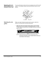
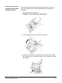
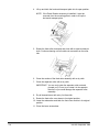
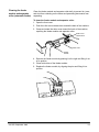
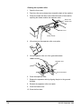
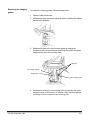
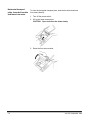
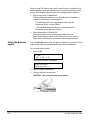
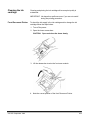
1
Document Scanner 5500 Document Scanner 7500 User’s Guide A-61070 Part No. 1E8132 Safety Information for Installation Instructions for the Kodak Digital Science Document Scanner 5500 and 7500 IMPORTANT: Equipment shall be installed by qualified personnel. WARNING: Dangerous voltage. Disconnect the main power before installation. CAUTION: Hot surface, avoid contact ATTENTION: Eviter le contact, pieces brulantes VORSICHT: Heisse oberflaeche, beruehrung vermeiden Safety Information for User/Installation Instructions for the Kodak Digital Science Automatic Document Feeder IMPORTANT: Equipment shall be installed by qualified personnel. WARNING: Dangerous voltage. Disconnect the main power before installation. CAUTION: Moving parts, avoid contact ATTENTION: Eviter le contact, pieces en mouvement VORSICHT: Bewegliche teile, beruehrung vermeiden 1 Introduction This manual supports the Kodak Digital Science Document Scanners 5500 and 7500. The Kodak Digital Science Document Scanner 5000/7000 series scanners are high-speed, high-resolution rotary scanners designed for medium- to high-volume digital capture of business documents. The Document Scanners capture printed characters, handwritten text, and graphics from documents of various sizes and thicknesses in an electronic format for indexing and database storage. This manual explains how to set-up, operate, maintain and troubleshoot the Document Scanner 5000/7000 series scanners. NOTE: Illustrations in this User’s Guide are shown using the semiautomatic feeder. Scanner features A-61070 September 1999 The Document Scanners 5500/7500 have the following features: • Scans up to 120 pages per minute (Scanner 7500 — standard sized documents fed in landscape orientation; continuous transport using the semi-automatic feeder). • High-speed scanning and image resolution. ◊ Scanner 5500 scans 80 landscape (A4 size) or 60 portrait (8 ½ x 11-inch) documents per minute at 200 dpi or 40 landscape (A4 size) or 30 portrait (8 ½ x 11-inch) documents per minute at 300 dpi. ◊ Scanner 7500 scans 120 landscape or 90 portrait documents (8 ½ x 11-inch or 216 x 279 mm) per minute at 200 dpi or 80 landscape or 60 portrait documents per minute at 300 dpi. • Handles documents of up to 2.5 to 20 in. (64 to 508 mm) long, 2.5 to 12 in. (64 to 305 mm) wide, and 0.014 in. (0.36 mm) thick. The gap release feature allows thicker documents to be scanned. • Manual or automatic feeding — documents can be hand-fed one at a time or stacked up to 1.5 inches (38 mm) or approximately 300 documents of 20-pound stock. • Front and rear scanning allows scanning of one or two sides of a document in a single pass. • Easy operation — documents enter and exit the scanner in the same order. • Easy-to-reach control panel keys. • A high-speed document transport system. • Document skew monitoring. • Multi-feed detection via length monitoring • A two-line, status display which displays image addresses, current application modes and error messages. 1-1 Scanner options 1-2 • Full programmability of all 18 application modes with override capability. • Audible tones for selected functions such as footswitch, patch reading, etc. • English or other language message display. • Convenient table-top size. • An adaptable, modular design for easy addition of accessories. The following optional accessories are available for use with your scanner: • A choice of feeders — automatic document feeder or a semiautomatic document feeder. • Document printer(s) which provide pre-scan (front) and/or post-scan (rear) capability. • A bar code reader for decoding encoded information. • A patch reader for automatic document level control. • A footswitch for document level control. • A universal stand which has a large, built-in workshelf. A-61070 September 1999 Scanner components The following illustrations and descriptions will help you locate and become familiar with scanner components. Front View — Document Scanners 5500/7500 (shown with semi-automatic feeder) Anti-static brush Exit hopper side guides Exit hopper Control panel End stop Feed and separator rollers Gap adjustment knob Gap release lever Self-centering feed tray Feed tray side guides Anti-static brush — minimizes the static build-up on the documents before they are deposited in the exit hopper. Exit hopper side guides — adjustable to accommodate the size of your documents to aid in neat and even stacking. Exit hopper— collects documents after they have been scanned. End Stop — keeps documents in place as they exit the scanner. Feed and separator rollers — provides smooth document feeding of various sizes and textures. Self-centering feed tray — centers documents in the transport for reduced skew and cropping control. Control panel — contains the status display, indicators, and operating keys used to control the scanner. Gap adjustment knob — allows you to manually adjust the space between the feed and separator rollers for documents of varying thicknesses. Gap release lever — allows you to open the feed gap to allow thicker documents to be fed into the transport. Feed tray sides guides — holds documents prior to feeding. A-61070 September 1999 1-3 Rear View — Document Scanners 5500/7500 Footswitch connector Coin 1/3 Coin 2 Serial # SCSI connectors Power switch Power cord connector Footswitch connector — allows you to plug in the optional Footswitch accessory. Serial number — provides the serial number and agency approvals. Power switch — toggle this switch to turn the power on (|) or off (O). Power cord connector — plugs into an appropriate power outlet. Coin 1/3 — service/diagnostic interface. Configures the scanner and runs diagnostics. Coin 2 — not for customer use. SCSI connectors — SCSI interface connection for the scanner. For European units only: WARNING: 1-4 Communications between the Scanner 5500/7500 and the host computer including both the SCSI cable (TDK: HF70RH26X29X13) and RS-232 cable (TDK: HF70RH12X15X7.3) must have ferrite cores. These ferrite-cored cables are used for radio frequency interference suppression. A-61070 September 1999 Control panel The control panel consists of the status display and the operation keys and indicators. Status display The status display indicates the image address, current application mode and error messages. Scanner status Mode number Scanner Status — displays if the scanner is enabled or disabled. Mode Number — displays the current mode number or name. Fixed field — an alphanumeric field containing fixed information, i.e., the date. Delimiters — used to separate the levels in an image address. Delimiters can be displayed in different locations (as shown above) based upon system configuration. Level I — when pressed, will identify the next document as a Level 1 document. Level II — when pressed, will identify the next document as a Level 2 document. Level III— when pressed, will identify the next document as a Level 3 document. A-61070 September 1999 1-5 Operating keys and indicators Following is an illustration and a description of the operating keys and indicators. Two-line status display Key/Indicator Image buffer status Contrast thumbwheel Numeric keys (0-9) Decimal key F key C 1-6 Function Front — green indicates the front side image buffer is available for scanning; red indicates the buffer is not available and the feeder is off (for simplex- and duplex-defined application modes). Back — green indicates the rear side image buffer is available for scanning; red indicates the buffer is not available and the feeder is off (for duplex-defined application modes only). Allows you to adjust the display contrast between the characters and the background in the display. Used with the Enter key to enter numeric data such as an image address or function code. Allows you to insert a field separator in an image address. Selects one of the available functions when used with the numeric keys. Clear or Cancel. Allows you to cancel a function without changing the preset value(s). Also used to clear error messages from the status display. A-61070 September 1999 Operating keys and indicators Keys/Indicators Function Next Allows you to enter the next document image address. + Allows you to enter a new value for the image address. When pressed, it allows a field to remain unchanged. Enter Used to enter numeric data for a function code or an image address change. Back Used to move the cursor back one space during numeric data input (the last data input is erased). CAL Starts the calibration process. End Press End to stop the feeder and transport system at the end of a batch or job and alert the host computer that the batch or job has ended. When pressed, the documents in the transport system will be scanned and stacked faced down in the exit hopper before the transport is disabled. Jog Momentarily turns on (jogs) the transport system to help document jams. Level 3 key Identifies the next document fed into the scanner as a Level 3 document. Level 2 key Identifies the next document fed into the scanner as a Level 2 document. Level 1 key Identifies the next document fed into the scanner as a Level 1 document. Run Turns on the feeder and transport system. Stop Stops the feeder and transport system. When Stop is pressed, documents in the transport system will be scanned and placed in the exit hopper before the transport system stops. Confirmation tone/alarm A-61070 September 1999 The confirmation tone/alarm is located under the control panel and sounds when one of the following conditions occur: • Run is pressed (one long tone). • Stop or End is pressed (many short tones followed by a long tone). • Feeder clutch engages/disengages (one short tone). • Incorrect key is pressed (three short tones). • Document skew is greater than what is setup in the skew parameter, or when a document is shorter or longer than the specified length parameters (one short tone). • A bar code is detected (if the accessory is enabled and the confirmation tone is enabled). • A patch code is detected (if the accessory is enabled and the confirmation tone is enabled). • The Footswitch is detected (if the accessory is enabled and the confirmation tone is enabled — one short tone). 1-7 2 Getting Started The following steps are necessary to prepare the scanner for operation. Procedures on how to perform these steps are described in this chapter. 1. Turn on the power to the scanner. 2. Select the language display. 3. Calibrate the scanner. 4. Prepare the documents for scanning. 5. Adjust the feed and separator roller gap, if required (semi-automatic feeder). 6. Adjust the feed shelf position. 7. Adjust the feed shelf side guides. 8. Adjust the exit hopper side guides and end stop. 9. Select the desired application mode and image level, or the Count Only function. 10. Start the scanner from the host computer. (This step is not necessary for the Count Only function.) 11. Press Run. 12. Feed the documents into the scanner. 13. Press Stop or End, depending on whether the batch or job has been completed. NOTE: After you press Stop, Run can be pressed again and more documents can be fed into the scanner. After pressing End, you must enable the scanner from the host computer before scanning again. Turning on the scanner Follow the steps below to turn on the power to the scanner. 1. Turn on the power switch (located at the rear of the machine). NOTE: Several initialization messages will appear in the status display. If you cannot see any messages, try adjusting the contrast. 2. Send the Scan command from the host computer to the scanner. The message Enabled will appear in the status display. The current application mode and next image address will also be displayed. IMPORTANT: Do not use the operating keys until the Warming Up Completed message has been displayed. Entries made before this message is displayed will not be recognized by the scanner. A-61070 September 1999 2-1 Selecting the language display The scanner may have been configured at installation to allow use of a second language in the status display. The language used (French, German, Italian, Spanish, or other) is defined during installation. If available, the alternate language display may be accessed using function code F19. Calibrating the scanner Calibration sets the intensity of the lamps, which contribute to the overall quality of the scanned document image. The scanner should be calibrated: • at least once a day • if image quality is poor • after changing lamps Calibrate the scanner using a calibration target (sheet of paper) that is: • • • • • Blank Clean Matte finish (not glossy) White or the same color as the background color of the documents to be scanned. When using a duplex-defined application mode, make sure that both front and rear colors of the calibration target correspond with the front and rear colors of the documents to be scanned. If you are scanning a variety of colored documents, use a white calibration target. Wider than the documents you are going to scan (i.e., to scan 8.5 x 11 inch (216 x 279 mm) portrait orientation documents, the calibration target should be wider than 8.5 inches (216 mm). The recommended width for the calibration target is 12 inches (300 mm). To scan 11 x 17-inch (280 x 432) documents, the calibration target should be wider than 11 inches (279 mm) but not wider than 12 inches (305 mm). • Between 12 and 25.5 inches (305 and 648 mm) long. For your convenience, 12 x 12-inch calibration targets (Part # 986527) are supplied with the scanner and are also available from Parts Services, 1 800 431-7278. To calibrate the scanner: 1. Verify the power switch is on and a normal operating status display is displayed. 2. Press CAL on the control panel. A message will be displayed prompting you to feed the calibration target. 3. Insert the calibration target into the feeder. When calibration is successful, the status display returns to a normal operating display. 2-2 A-61070 September 1999 Unsuccessful calibration If calibration is not successful, a message appears in the status display. You may need to: • Verify you are using a clean, blank sheet of paper (at least 12 inches in length) as a calibration target. The paper must be wider than the documents being scanned and at least 8 1/2 inches long. • Verify there is not a document already in the document path. (Refer to the section entitled, “Clearing the document path” in Chapter 7.) • Clean the imaging guides. (Refer to the section entitled “Cleaning the imaging guides” in Chapter 5.) • Calibrate the scanner again. If calibration fails again, change the lamps. (Refer to the section entitled, “Replacing the exposure lamps” in Chapter 5.) If you have done all of the above and calibration still fails, contact your service representative. Preparing documents for scanning Before you begin processing documents, make certain the documents may be fed through the scanner easily: • Remove any staples, rubber bands, loose mending tape, or paper clips from the documents to be processed. • Straighten wrinkled edges and tape any torn documents. • Trim ragged edges. When using the semi-automatic feeder, make certain all documents are of similar size, texture, thickness and weight, and the leading edges of all documents are aligned. Document orientation Before scanning, position all documents the way you want them to be displayed on the host computer. Feed the documents so the text or graphic appears to be facing in the same direction. Document sizes The following document sizes can be scanned: Length 2 ½ x 17 inches (64 x 432 mm). Documents between 17 and 30* inches (508 mm) long can be scanned by adjusting the exit hopper end stops. Width 2 ½ x 12 inches (64 x 305 mm) Minimum document thickness: onion skin (0.0015-inch / 0.04 mm) Maximum document thickness: index card (0.014 inch / 0.36 mm) index card (0.040 inch / 1.00 mm) * when equipped with the Kodak Digital Science Document Image Manager. A-61070 September 1999 2-3 Adjusting the feed and separator roller gap (semi-automatic feeder) The gap adjustment knob on the control panel increases or decreases the space between the feed and separator rollers. The gap must be adjusted properly for smooth transportation of documents without document overlap. When documents of different thicknesses are fed in a group, adjust the gap using the thinnest document in the group. The feed and separator roller gap may have to be adjusted to compensate for: • Very thin documents (onion skin, tracing paper, etc.). • Very thick documents (card stock, punch cards, cover stock). • Some coated documents (photographic paper, plastic-coated paper). If the gap is not adjusted properly: • More than one document at a time may be drawn into the transport system at the same time; not all of the documents will be scanned. • Documents may be drawn into the transport too quickly; documents may overlap or be spaced too closely (causing an error display). • Documents may become skewed during transport; jamming may occur. NOTE: Prior to performing the adjustment procedure, the scanner must be calibrated and enabled. To adjust the feed and separator roller gap: 1. Verify that the power switch is on. 2. Turn the gap adjustment knob clockwise three complete turns to open the gap between the feed roller and separator roller. Gap adjustment knob 3. Enter F04 and enable Counting Only. 2-4 A-61070 September 1999 4. Press Run. 5. Select two documents of the same size, texture and thickness, similar to the types of documents you will be scanning. 6. Place one document on top of the other. Hold the documents firmly by their trailing edges. Insert them into the gap approximately 1/8 in. (3 mm). Bottom document separates from top document 7. If the documents separate, repeat the following steps until the documents do not separate: • Turn the gap adjustment knob clockwise 1/2 turn. • Insert the documents again. If the documents do not separate, proceed with Step 8. 8. Rotate the gap adjustment knob counterclockwise 1 or 2 clicks. IMPORTANT: Do not make a gap adjustment while documents are in the feeder or transport system; doing so will produce an inaccurate adjustment. 9. Hold the trailing edges of the documents firmly. Insert them into the gap. • If the bottom document is not separating from the top document, remove the documents and repeat Steps 7 and 8 until the bottom document separates from the top document by approximately 1 in. (25.4 mm). • If the bottom document is separating from the top document, proceed with Step 10. 10. When you have adjusted the gap so the bottom document separates consistently from the top document, rotate the gap adjustment knob counterclockwise another 1 or 2 clicks to complete the adjustment. 11. Feed a stack of 50 to 100 documents twice through the transport system. Verify the final count reflects the total number of documents fed and that the counter shows the same amount each time the documents are counted. If the count is not the same, the gap is not adjusted correctly. Rotate the gap adjustment knob counterclockwise another 1 or 2 clicks and repeat Step 9. Repeat until corrected. A-61070 September 1999 2-5 12. Press Stop. 13. Enter F04 and disable Counting only. 14. Press Enter. Adjusting the separator roller to scan thick documents To scan thick documents (card or cover stock), use the gap release lever to increase the gap between the feed roller and separator roller. Gap release lever 1. Press down and hold the gap release lever. This opens the gap between the feed and separator rollers and allows thick documents to pass between the rollers. 2. Manually feed the thick documents while holding down the gap release lever. Thick document 2-6 A-61070 September 1999 Adjusting the feed shelf position (semiautomatic feeder only) For manual feeding, the feed shelf can be adjusted in the 0°, 30° or 40° position. For automatic feeding, raise the feed shelf to the 30° or 40° position. 40° position Adjusting the side guides 30° position Before you begin feeding documents into the scanner, adjust the position of the side guides and feed shelf position. • Adjust the width of the feed shelf side guides to hold the widest document you will be scanning. Leave approximately 1/16-inch (2 mm) clearance on each side of the largest document to allow for proper feeding. NOTE: Ensure that the documents are center-fed so each document covers the 2 ½-inch required width as indicated by the label on the feed tray. A-61070 September 1999 2-7 Adjusting the exit hopper side guides and end stop The exit hopper side guides and end stop must be adjusted so documents are stacked properly. 1. Adjust the exit hopper side guides to hold the widest document you will be scanning. Leave ¼-inch (5 mm) clearance on each side of the document. 2. Adjust the end stop to hold the longest document you will be scanning. An end stop extension is included to accommodate documents up to 17 inches in length. To attach the end stop extension: • Fold the spring-loaded exit hopper end stop down and slide the extension’s tabs into the slits just above the exit hopper end stop. To remove the end stop extension: • Press the spring-loaded exit hopper end stop and pull the extension out from the exit hopper. End stop extension Tabs Slits Exit hopper end stops 2-8 A-61070 September 1999 3. Adjust the height of the exit hopper so the scanned documents naturally fall between the exit hopper side guides and exit hopper end stop. The exit hopper has three height positions: • • • Standard position 10° from standard position 20° from standard position (specifically for use with A4 size, onion skin documents) Standard position 10° from standard position 20° from standard position A-61070 September 1999 2-9 3 Operating the Scanner Overview This chapter provides instructions for selecting modes, image level settings and feeding documents using the semi-automatic feeder and the automatic feeder. The scanning process consists of the following steps: 1. Prepare the scanner for operation (refer to Chapter 2, Getting Started for more information). 2. Select an application mode for the application. 3. Select the appropriate operating values required for the application on the host computer. 4. Press the Run key. 5. Feed documents into the transport (refer to “Feeding Documents using the semi-automatic (or automatic) feeder” later in this chapter). • The scanner assigns a sequential ID number, the document image level and image address. • The document is scanned. • The document image header is created. • The host computer initiates transfer of the document image header and document image to the host system for storage on magnetic or optical disk media. • Documents are deposited in the exit hopper, face down, in the order in which they were fed into the transport. 6. Press Stop to disable the transport after the last document has been scanned or press End to alert the host computer that the batch or job has ended. NOTE: A-61070 September 1999 If Stop or End is pressed while scanning a stack of documents, the feeder will stop. Any documents in the transport system will be scanned and deposited face down in the exit tray before the transport system is disabled. 3-1 Setting image levels Image levels are used to identify specific types of documents (or sets of documents) for later indexing and retrieval. The image level assigned to each document is inserted into the image header associated with the document image. There are four document image levels: • • • • Level 0 Level 1 Level 2 Level 3 Setting Levels Levels 1, 2, and 3 can be set by pressing a document Image Level key on the control panel, or by using the optional Footswitch or Patch Reader accessories. Level 0 can be set by entering function code F07. Selecting a mode The scanner offers 18 modes that may be programmed for a particular application or group of applications. When you select a mode for use with a particular application, you are selecting the format/appearance of the output. Each mode is composed of definitions that affect the output of the scanner. The required mode definitions include language display, measurement format, index format, image address rules, level rules, accessory status, etc. The modes are programmed at the time of installation and stored for easy access and use. Many of the optional mode definitions set up during installation may be overridden using function codes. The overrides are temporary, unless it is specified during installation that the mode overrides are to be saved. Detailed information regarding application modes, can be found in Kodak publication, A-61097, Mode Setup Software. Typically, the mode is selected via the host system, using a scannerunique command. However, you may manually select a mode. To select a mode do the following: 1. Enter function code F01 (Select Mode) by pressing the F key and the numeric keys 0 and 1. 2. Press Enter. 3. Enter the desired mode number (modes range from 1 to 18). 4. Press Enter. 3-2 A-61070 September 1999 Temporary operating values Each of the 18 modes programmed at the time of installation contain definitions that affect the output of the scanner. Each mode is programmed to conform to the output requirements of a particular application or group of applications. There may be instances, however, when a particular application requires some variation of an existing mode. In such instances, mode definitions may be changed using available function codes. See Chapter 4, Function Codes, for a listing and description of the available function codes. NOTE: A-61070 September 1999 Changes to mode definitions remain in effect until another mode is selected or the side panel switch is turned off. The original mode definition is only affected by these changes if the mode overrides are saved (the mode override option may be selected at installation and if selected, a plus sign (+) appears in the first line of the status display). 3-3 Feeding documents using the semiautomatic feeder Following are feeder instructions using the semi-automatic feeder. After the scanner has been prepared for operation, the desired mode and any temporary operating values have been defined, you are ready to feed documents into the transport. 4. Verify that the power is on and that all of the proper adjustments have been made (feeder side guides, exit hopper side guides, etc.). 5. Place the feed shelf in the Up position. 6. Select a stack of documents that is no more than 1.5 in. (38 mm) thick. Hold the stack with the front sides facing up and the top of the documents facing toward the scanner. Tap the bottom edge of the stack against a flat surface so the documents are in an even bundle. 7. Fan the stack of documents so the leading edge of the top document sticks out the farthest. Fanned documents 40° position 8. Press Run. 9. Place the stack of fanned documents into the feeder so the leading edge of the top document contacts the feed/separator rollers. The documents are drawn into the transport, with the top document being fed first. The documents are deposited in the exit hopper face down, in the order in which they were fed into the transport. NOTE: Be sure the documents are center-fed so each document covers the 2 ½-inch required width as indicated by the label on the feed tray. Each document should automatically go into the feeder. If the automatic flow is inhibited, gently push the top document toward the feeder to re-establish automatic feeding. 3-4 A-61070 September 1999 7. As you scan documents, set the image level, as required, and periodically remove documents from the exit hopper. NOTE: When the image buffer is full, the feeder will turn off and the image buffer status light will turn red. There may be a momentary pause in scanning while images are being transferred to the host computer. Scanning will resume and the status indicator will change to green when the image buffer is clear. 8. Press Stop to disable the transport system after the last document has been scanned, or press End to alert the host computer the batch or job has ended and to disable the transport system after the last document has been scanned. Feeding documents manually To manually feed documents, follow the steps below: 1. Select the correct scanning operating values. 2. Place the feed shelf in the up or down position (semi-automatic feeder only), whichever is most convenient. 3. Insert the documents one at a time. NOTE: Be sure the documents are center-fed so each document covers the 2 ½-inch required width as indicated by the label on the feed tray. A-61070 September 1999 3-5 Feeding thick documents The gap release lever is used to feed thick documents such as card stock or cover stock. The lever is located on the front panel of the scanner next to the gap adjustment knob. (Graphic depicts movement of separator rollers when lever is used) (Graphic depicts gap adjustment) Gap release lever To feed thick documents using the gap release lever: 1. Press down and hold the gap release lever; this opens the gap between the feed and separator rollers allowing thick documents to pass between them. You will be able to see the gap open as the lever is pushed down. 2. Insert the thick document past the rollers until it is taken into the transport system. NOTE: If more than one thick document is to be scanned, feed them into the transport one at a time. 3. After the thick document(s) have been scanned, release the gap release lever; it will return to its original position. The feed and separator rollers will return to their previously adjusted positions. 3-6 A-61070 September 1999 Feeding documents using the automatic feeder Following are document feeder instructing using the automatic feeder. After the scanner has been prepared for operation, the desired mode and any temporary operating values have been defined, you are ready to feed documents into the transport. 1. Verify that the power is on and that all of the proper adjustments have been made (feeder side guides, exit hopper side guides, etc.). 2. Select a stack of documents that is no more than 1.5 in. (38 mm) thick. Hold the stack with the front sides facing up and the top of the documents facing toward the scanner. Tap the top edge of the stack against a flat surface so the documents are in an even bundle. 3. Fan the stack of documents so the leading edge of the top document sticks out the farthest. 4. Lift the feeder module and slide the top edge of the documents underneath the feeder module. To help prevent multiple feeds, after you place the documents under the feeder module, pull the documents back slightly (about ¼-inch) from the separator roller. 5. Press Run. NOTE: Be sure the documents are center-fed so each document covers the 3 ½-inch required width. 6. As you scan documents, set the image level, as required, and periodically remove documents from the exit hopper. NOTE: When the image buffer is full, the feeder will turn off and the image buffer status light will turn red. There may be a momentary pause in scanning while images are being transferred to the host computer. Scanning will resume and the status indicator will change to green when the image buffer is clear. 7. Repeat Steps 2 through 4 until all the application documents have been fed into the transport. 8. Press Stop to disable the transport system after the last document has been scanned, or press End to alert the host computer the batch or job has ended and to disable the transport system after the last document has been scanned. A-61070 September 1999 3-7 4 Function Codes Using function codes There are a variety of functions available which may be used to temporarily change operating values, and to obtain system and accessory status information. These functions are listed in the Function Code Summary later in this chapter. Following are the procedures for using function codes: 1. Press the F key. 2. Press the numeric keys which correspond to the desired function code. 3. Press Enter. If the function is used to enable or disable an operation (turn an option on or off): 1. Press 1 to turn the option On, or 0 to turn the option Off. 2. Press Enter. If the function requires numeric input: 1. Press the numeric key(s) required. 2. Press Enter. If the function is used to increment or decrement a measurement: 1. Press the arrow keys to increment or decrement as follows: • Press the Up arrow to increment the measurement by 1 inch (25 mm), or • Press the Down arrow to decrement the measurement by 1 inch (25 mm), or • Press the Right arrow to increment the measurement by 1/8inch (3 mm), or • Press the Left arrow to decrement the measurement by 1/8-inch (3 mm). 2. Press Enter. To cancel a function (before pressing Enter) or clear the status display after executing a function code: • A-61070 September 1999 Press C (Clear/Cancel). 4-1 Function code summary Following is a summary of the functions and their corresponding function code: Application Modes Select Application Mode........................................................ F01 Restore Application Mode ..................................................... F02 Index/Image Address Level 0 .................................................................................. F07 Last Image Address .............................................................. F08 Status Accessory Status .................................................................. F05 Transport System Operation Time ........................................ F17 Date and Time ..................................................................... F23 Counters Count Only............................................................................ F04 Total Document Count .......................................................... F09 Level 0 Count........................................................................ F10 Level 1 Count.........................................................................F11 Level 2 Count........................................................................ F12 Level 3 Count........................................................................ F13 Reset Level Counts............................................................... F14 Setup Display Language ................................................................. F19 Measurement System ........................................................... F20 Set Time .............................................................................. F21 Set Date ............................................................................... F22 Controls Length Monitor ...................................................................... F70 Omit Length Monitor on Next Document ............................... F71 Skew Monitor ........................................................................ F72 Host Latch Flag ............................................................................. F73 Momentary Flag .................................................................... F74 Patch Reader Patch Reader ....................................................................... F50 Confirmation Tone................................................................. F53 Omit Patch Reading on Next Document................................ F54 Patch Test ............................................................................. F55 4-2 A-61070 September 1999 Bar Code Reader Bar Code Reader ................................................................. F60 Confirmation Tone................................................................. F63 Omit Patch Reading on Next Document................................ F64 Bar Code Test ....................................................................... F65 Document Printers Front and Rear Document Printers ...................................... F40 Front Document Printer ........................................................ F41 Rear Document Printer ........................................................ F42 Omit Printing on Next Document........................................... F44 Print Test............................................................................... F45 Vertical Start Print Position (Front) ........................................ F46 Vertical Start Print Position (Rear)......................................... F47 Purge Print Head .................................................................. F48 Footswitch Confirmation Tone................................................................. F75 A-61070 September 1999 4-3 Function code listing Code F01 Following is a listing of the function codes and descriptions. Function Code Name Select Mode Description Allows you to select one of the predefined application modes. Enter a value from 1 to 18 and press Enter. Allows you to restore the current application mode to its default status, provided mode overrides are not saved. Allows you to count the number of documents entering the scanner without scanning. Enter 1 to turn Counting Only on, or 0 to turn Counting Only off and press Enter. Displays the current status of each accessory installed. Press the Down arrow to view the status of the next accessory, or press the Up arrow to view the status of the previous accessory. F02 Restore Mode F04 Counting Only F05 Accessory Status F07 Level 0 Allows you to define the next document scanned as a Level 0 document. F08 Last Image Address F09 Total Document Count F10 Level 0 Count Allows you to display the image address of the last document scanned. Allows you to display the total number of documents that entered the feeder (Level 3, Level 2, Level 1 or Level 0). Press 0 to reset the counter and then press Enter. Allows you to display the total number of documents that have entered the feeder as Level 0 documents. Press 0 to reset the counter and then press Enter. F11 Level 1 Count Allows you to display the total number of documents that have entered the feeder as Level 1 documents. Press 0 to reset the counter and then press Enter. F12 Level 2 Count Allows you to display the total number of documents that have entered the feeder as Level 2 documents. Press 0 to reset the counter and then press Enter. F13 Level 3 Count F14 Reset Level Counts Allows you to display the total number of documents that have entered the feeder as Level 3 documents. Press 0 to reset the counter and then press Enter. Allows you to reset all the level counters (Level 0, Level 1, Level 2, and Level 3) to 0. 4-4 A-61070 September 1999 Code Function Code Name Description F16 Alarm Tone Allows you to adjust the pitch of the alarm tone. Press the Up arrow to increase the pitch or press the Down arrow to decrease the pitch, then press Enter. F17 Transport System Operation Time Allows you to display the elapsed time of operation of the transport system. This time is recorded in the software and will be reset if a ROM replacement is performed. Therefore, the software time displayed and the time displayed inside the side access door can vary. F19 Display Language Allows you to choose your preferred language. The options are: 0 = English 1 = Japanese 2 = French 3 = German F20 Measurement System Allows you to choose your preferred measurement system. The options are: 0 = millimeters 1 = inches F21 Set Time Allows you to set the time on the status display. The format is HH:MM. HH represents the hours (on a 24-hour clock) and MM represents the minutes (valid values are 00 to 59). Enter the new time in the format illustrated and press Enter. F22 Set Date Allows you to set the date on the status display. The format is YYYY/MM/DD. YYYY represents the year, MM represents the month (valid values are 01 to 12), and DD represents the day (valid values are 01 to 31). Enter the new date in the format illustrated and press Enter. F23 Time and Date Display Allows you to view the current time and date. F40 Front and Rear Document Printers On/Off Allows you to turn the Front and Rear Document Printers on or off. Enter 1 to turn on or 0 to turn off. F41 Front Document Printer On/Off Allows you to turn the Front Document Printer on or off. Enter 1 to turn on or 0 to turn off. F42 Rear Document Printer On/Off F44 Omit Printing on the Next Document Only Allows you to turn the Rear Document Printer on or off. Enter 1 to turn on or 0 to turn off. Allows you to specify no information be printed on the next document scanned. Printing will resume on subsequent documents. Enter 1 to omit printing on the next document, or enter 0 to print on the next document then press Enter. A-61070 September 1999 4-5 Code Function Code Name Description F46 Front Document Printer Vertical Start Print Position Allows you to specify how far from the leading edge of the document printed information will appear. Use the numeric keys to input values between 0.125 and 20 inches (3 to 508 mm) in increments of 0.125 (3mm). The value will correspond to the selected measurement system and should not exceed the document length. The horizontal start print position is changed manually. F47 Rear Document Printer Vertical Start Print Position Allows you to specify how far from the leading edge of the document printed information will appear. Use the numeric keys to input values between 0.125 and 20 inches (3 to 508 mm) in increments of 0.125 (3mm). The value will correspond to the selected measurement system and should not exceed the document length. The horizontal start print position is changed manually. F48 Purge Print Heads Allows you to purge and clean slightly hardened ink from the print head of the document printers. Feed a single blank document after the feed clutch engages. F50 Patch Reader On/Off Allows you to turn the Patch Reader on or off. Enter 1 to turn on or 0 to turn off, then press Enter. F53 Patch Reader Confirmation Allows you to turn the confirmation tone on or off which Tone On/Off informs you when the Patch Reader has successfully read a patch document. Enter 1 to turn on or 0 to turn off, then press Enter. F54 Omit Patch Reading on Next Document On/Off Allows you to omit patch reading on the next document scanned. Normal patch reading resumes with subsequent documents. Enter 1 to turn on or 0 to turn off, then press Enter. F55 Patch Test F60 Bar Code Reader On/Off F63 Bar Code Reader Confirmation Tone Allows you to test for patch position and patch quality. The test result will indicate: T-Patch, 2-Patch, 3-Patch or Patch Not Read. Allows you to turn bar code reading on or off. Enter 1 to turn on or 0 to turn off and then press Enter. Allows you to turn the confirmation tone on or off which informs you when the Bar Code Reader has successfully read a bar code document. Enter 1 to turn on or 0 to turn off and then press Enter. F64 Omit Bar Code Reading on the Next Document Only F65 Bar Code Test 4-6 Allows you to omit bar code reading on the next document scanned. Bar Code Reading will resume on subsequent documents. Enter 1 to turn on or 0 to turn off, then press Enter. Allows you to perform a test to verify bar code position, bar code quality and bar code read rate. A-61070 September 1999 Code Function Code Name Description F70 Length Monitor On/Off Allows you to turn the length monitor on or off. The length monitor checks the length of the documents scanned against the predefined minimum/maximum allowable lengths. Messages and/or confirmation tones alert you if the document is shorter or longer than the predefined length. F71 Omit Length Monitor on the Next Document Only Allows you to omit length checking on the next document scanned. Length monitoring will resume on subsequent documents. Enter 1 to turn on or 0 to turn off, then press Enter. F72 Skew Monitor Allows you to turn skew detection on or off which monitors the amount of skew using predefined skew angle(s). F73 Latched Flag On/Off Allows you to set a flag in the image headers which alerts the host system that this document, and those which follow, are of special interest. The flag will remain activated for every document until it is turned off. Enter 1 to turn on or 0 to turn off, then press Enter. F74 Momentary Flag Allows you to set a flag in the image header which alerts the host system that this document is of special interest. This flag is set only for that one document. Enter 1 to turn the momentary scanning flag on, then press Enter. F75 Footswitch Confirmation Tone Allows you to turn the confirmation tone on or off which informs you when the Footswitch is pressed and/or released. Enter 1 to turn on or 0 to turn off, then press Enter. A-61070 September 1999 4-7 5 Maintenance This chapter provides maintenance procedures for the scanner including cleaning and part replacement procedures. Cleaning tasks To keep your scanner in good operating condition, the following tasks must be performed periodically: • Cleaning the imaging guides (daily) • Cleaning the feed and separator roller (semi-automatic feeder) (daily) • Cleaning the feeder module and separator roller (automatic feeder) (daily) • Cleaning the paper path (daily) • Vacuuming inside the scanner (weekly) • Cleaning the cabinet (weekly) For additional maintenance and feeder adjustment information, see Kodak publication A-61603. Feeder and Maintenance Adjustment Procedures. Cleaning materials Materials needed to perform all maintenance procedures are: • A mild cleaning agent • A soft, clean, lint-free cloth • A soft-bristled cleaning brush • A vacuum cleaner • Staticide Wipes • Paper Path Cleaner IMPORTANT: Do not use any unauthorized commercial cleaning solvent in any of the cleaning procedures. Replacement parts Consumable parts that can be replaced by the customer include: • Imaging guides • Exposure lamps • Automatic Document Feeder Module • Automatic Document Feeder Separator Roller Instructions on how to replace these parts are included later in this chapter. A-61070 September 1999 5-1 Daily maintenance procedures Maintenance procedures that should be performed daily include cleaning the imaging guides, feed and separator rollers and the paper path. Cleaning the imaging guides To clean the imaging guides, follow the steps below: IMPORTANT: Do not use any abrasive materials when cleaning the imaging guides. This includes abrasive cleansers, commercial solvents, paper towels, or coarse cloths. 1. Open the side access door. 2. Release and open the vertical transport plate by rotating the release handle 180° clockwise. 3. Release and remove the front imaging guide by rotating the thumbscrew 90° counterclockwise, and lifting the guide’s two green saddle mounts from the mounting shaft. Magnets Front imaging guide Thumbscrew Rear imaging guide 5-2 A-61070 September 1999 4. Release and remove the rear imaging guide by swinging the guide toward the front of the scanner (to release it from the two magnets), and lifting it from the scanner’s two mounting pins. 5. Clean the surfaces of both the front and rear imaging guides with an antistatic wiper or a clean, soft, lint-free cloth, slightly moistened with water or lens cleaner. 6. Dry the imaging guides with a dry, lint-free cloth. 7. Hold the rear imaging guide by the edges and carefully set it back into the scanner by seating it on the mounting pins. Swing the guide toward the rear of the scanner to fix it to the two magnets. NOTE: Look through the upper access door and side access door to make sure the imaging guide is mounted correctly. There are two sets of pins. Make sure the guide is seated on the small, lower set of pins. When the rear imaging guide is seated correctly, the top of the guide will sit approximately a ½-inch (10 mm) from the vertical transport plate. The rear imaging guide will become flush with the plate when the plate is closed. Rear imaging guide saddle mount Rear imaging guide mounting pin 8. Hold the front imaging guide by the edges and carefully set it back into the scanner by seating the guide’s two green saddle mounts on to the mounting shaft, and rotating the front imaging guide thumbscrew 90° clockwise. NOTE: Look through the upper access door and side access door to make sure the imaging guide is mounted correctly. The bottom of the front imaging guide must be seated just inside the vertical transport plate. The front imaging guide could be damaged if it is seated incorrectly when the vertical transport plate is closed. Front imaging guide saddle mount Vertical transport plate A-61070 September 1999 5-3 9. Swing the vertical transport plate closed and rotate the release handle 180° counterclockwise (so the red arrow aligns with the red rectangle) to latch the plate. Red arrow Red rectangle 10. Close the side access door. 11. Release and lower the horizontal transport plate back into its original position. 12. Lower the release bar and latch the front scan module into its original position. 13. Close the lower access door. 14. Close the upper access door. 5-4 A-61070 September 1999 Cleaning the feed and separator rollers (semiautomatic feeder) Clean the feed and separator rollers daily to prevent ink, toner, and dust from collecting on the rollers and preventing documents from separating. 1. Lift open the lower access door. CAUTION: Open and close the doors slowly. 2. Lift the release bar to raise the front scan module. 3. Rotate the feed roller cover release lever downward while rotating the feed roller cover to expose the rollers. Do not attempt to remove the assembly. A-61070 September 1999 5-5 4. Lift up and latch the horizontal transport plate into its open position. NOTE: If the Patch Reader accessory is installed, it must be removed from the mounting plate in order to lift up the horizontal transport plate. 5. Rotate the feed roller downward and clean with a water-moistened cloth. Continue cleaning until all residue is removed from the roller ribs. 6. Clean the surface of the feed roller assembly with a dry cloth. 7. Clean the separator roller with a dry cloth. IMPORTANT: You can only rotate the separator roller outward (toward you). Do not try to rotate it in the opposite direction or you could damage the separator roller assembly. 8. Dry all cleaned areas with a dry, lint-free cloth. 9. Rotate the feed roller cover down to its original position. 10. Lower the release bar and latch the front scan module in its original position. 11. Close the lower access door. 5-6 A-61070 September 1999 Cleaning the feeder module and separator roller (automatic feeder) Clean the feeder module and separator roller daily to prevent ink, toner, and dust from collecting on the rollers and preventing documents from separating. To clean the feeder module and separator roller: 1. Open the front cover. 2. Push the roller cover release lever toward the back of the machine. 3. Grasp and rotate the roller cover toward the back of the machine, exposing the feeder module and separator roller. Roller cover release lever Roller cover Feeder module 4. Remove the feeder module by pushing it to the right and lifting it out of its position. 5. Clean both rollers of the feeder module. 6. Replace the feeder module, by aligning the pins and fitting it into position. A-61070 September 1999 5-7 Cleaning the separator roller: 1. Open the front cover. 2. Push the roller cover release lever toward the back of the machine. 3. Grasp and rotate the roller cover toward the back of the machine, exposing the feeder module and separator roller. Roller cover release lever Roller cover Feeder module 4. Lift and remove the separator roller cover plate. 5. Lift the separator roller out of the grooved brackets. Separator roller Grooved brackets 6. Clean the separator roller. 7. Replace the separator roller by aligning the pins in the grooved brackets. 8. Reinsert the separator roller cover plate. 9. Close the feeder cover. 10. Close the front door. 5-8 A-61070 September 1999 Cleaning the paper path NOTE: Before doing the following procedure, clean the machine thoroughly and use the roller cleaning pads to clean the feed and separator rollers — start with a clean machine. Use the Paper Path Cleaning sheet to clean the paper path rollers. Periodically feed a cleaning sheet with the gum side up through the machine in both the portrait and landscape orientation. Regular use of Paper Path Cleaning sheets may result in fewer major cleanings with the roller cleaning pads. The paper path should be cleaned daily. Before you clean the paper path, be sure the feed and separator rollers and imaging guides have been cleaned. To clean the paper path: 1. To ensure complete coverage of the transport rollers, feed the cleaning sheet in the center, and to the left and right of the feeder document guides. 2. Repeat the procedure until no further residue is picked up by the cleaning sheet. 3. Using a clean Paper Path Cleaner sheet, repeat Step 1 to verify that the rollers are clean. 4. Turn the gum side down, and repeat Steps 1 through 3. NOTE: When the gum side is down, it may be necessary to hold down the gap release lever to allow the Paper Path Cleaner sheet to feed past the separator roller. NOTE: If there are feeder errors after cleaning the feed and separator rollers, refer to the section entitled “Adjusting the feed and separator roller gap”, in Chapter 2. A-61070 September 1999 5-9 Weekly maintenance procedures Maintenance procedures that should be performed weekly are vacuuming the inside of the scanner and cleaning the cabinet. Vacuuming inside the scanner Vacuum the inside of the scanner weekly or as required to remove any dust or debris. Vacuuming the horizontal transport area 1. Turn the power off. 2. Lift open the lower access door. CAUTION: Open and close the doors slowly. 3. Lift the release bar to raise the front scan module. 5-10 A-61070 September 1999 4. Lift up and latch the horizontal transport plate into its open position. NOTE: If the Patch Reader accessory is installed, it must be removed from the mounting plate in order to lift up the horizontal transport plate. 5. Vacuum the lower belt module and transport belts. WARNING: Do not make contact with any electrical components when vacuuming inside the scanner. 6. Release and lower the horizontal transport plate back into its original position. 7. Lower the release bar and latch the front scan module into its original position. 8. Close the lower access door. A-61070 September 1999 5-11 Vacuuming inside the side access door 1. Turn the power off. 2. Open the side access door. 3. Open the upper access door. 4. Release and open the vertical transport plate by rotating the release handle 180° clockwise. 5. Use a natural bristle cleaning brush to remove debris from inside the transport system. 5-12 A-61070 September 1999 6. Swing the vertical transport plate closed and rotate the release handle 180° counterclockwise. 7. Vacuum the side access door area. WARNING: Do not make contact with any electrical components when vacuuming inside the scanner. 8. Close the upper access door and side access doors. Cleaning the cabinet A-61070 September 1999 Clean the exterior of the scanner, the feed shelf, and exit hopper with a soft cloth. Remove any fingerprints, stains, or stubborn dirt with a cloth dampened with water or a mild cleaning agent. 5-13 Replacement procedures Replacement procedures should be performed on an as-needed basis. Components that need periodic replacement include the exposure lamps and imaging guides. Changing the lamps The exposure system consists of two special, long-life fluorescent lamps. The lamps slide in and out of the scanner for easy lamp replacement: • Always replace both lamps at the same time. If both lamps are not replaced, exposures may not be acceptable. • Use recommended lamps only. Other lamps may result in unacceptable image quality. Change the lamps every 500 hours, when required for error recovery, or when image quality is poor. WARNING: Make sure the lamps are cool before attempting to remove them from the lamp socket holder. To change the lamps: 1. Turn the power switch off. 2. Open the side access door. 3. Release the rear lamp cable connector from the scanner electrical system. 5-14 A-61070 September 1999 4. Pull the green rear lamp socket holder out from the scanner frame. Be sure to pull the lamp socket holder straight out along its axis. WARNING: Even though you can always handle the green lamp socket holder, the lamp may be very hot. Do not remove the lamp or the lamp socket holder until the lamp has cooled. NOTE: If the lamp socket holder pulls off from the lamp when removing the lamp and socket from the scanner, remove the lamp by grasping the lamp at the end, once it has cooled. 5. Once the lamp has cooled, remove the lamp from the lamp socket holder by carefully pulling the lamp straight out along its axis. 6. Replace the lamp, making sure that the clear slit on the lamp faces toward the document path. In the case of the rear lamp, the clear slit should face toward the front. CAUTION: Lamps are fragile. Do not force the lamp into place. A-61070 September 1999 5-15 7. Carefully insert the green rear lamp sock holder and rear lamp into the scanner frame. Be sure to insert the lamp socket holder straight in along its axis. 8. Connect the rear lamp cable connector to the scanner electrical system. 9. Repeat Steps 3 through 8, referring to the front lamp, noting that in Step 3 the front lamp cable must be released from the front lamp cable clip, and in Step 6 the clear slit should face towards the rear. In Step 8, the front lamp cable connector must be fashioned to the front lamp cable clip. 10. Close the side access door. 11. Perform the Calibration function. See the section entitled, “Calibrating the scanner” in Chapter 2. 5-16 A-61070 September 1999 Replacing the imaging guides To replace the imaging guides, follow the steps below: 1. Open the side access door. 2. Release and open the vertical transport plate by rotating the release handle 180° clockwise. 3. Release and remove the front imaging guide by rotating the thumbscrew 90° counterclockwise, and lifting the guide’s two green saddle mounts from the mounting shaft. Magnets Front imaging guide Thumbscrew Rear imaging guide 4. Release and remove the rear imaging guide by swinging the guide toward the front of the scanner (to release it from the two magnets), and lifting it from the scanner’s two mounting pins. A-61070 September 1999 5-17 5. Grasp and hold the new lower imaging guide by the green handle and carefully slide it into place. Make sure the grooves fully engage the track. Rear imaging guide saddle mount Rear imaging guide mounting pin 6. Hold the new front imaging guide by the edges and carefully set it back into the scanner by seating the guide’s two green saddle mounts on to the mounting shaft, and rotating the front imaging guide thumbscrew 90° clockwise. NOTE: The imaging guides are not interchangeable. They can only be inserted one way. Look through the upper access door and side access door to make sure the imaging guide is mounted correctly. There are two sets of pins. Make sure the guide is seated on the small, lower set of pins. When the rear imaging guide is seated correctly, the top of the guide will sit approximately a ½-inch (10 mm) from the vertical transport plate. The rear imaging guide will become flush with the plate when the plate is closed. Front imaging guide saddle mount Vertical transport plate 5-18 A-61070 September 1999 7. Swing the vertical transport plate closed and rotate the release handle 180° counterclockwise (so the red arrow aligns with the red rectangle) to latch the plate. Red arrow Red rectangle 8. Close the side access door. 9. Release and lower the horizontal transport plate back into its original position. 10. Lower the release bar and latch the front scan module into its original position. 11. Close the lower access door. 12. Close the upper access door. 13. Locate and grasp the end of the front imaging guide. Carefully slide the imaging guide out of its track. 14. Locate and grasp the end of the rear imaging guide. Carefully slide the imaging guide out of its track. 15. Grasp and hold the new rear imaging guide by the green handle and carefully slide it into place. Make sure the grooves fully engage the track. 16. Grasp and hold the new front imaging guide by the green handle and carefully slide it into place. Make sure the grooves fully engage the track. NOTE: The imaging guides are not interchangeable. They can only be inserted one way. 17. Close the right-side access door. A-61070 September 1999 5-19 Replacing the feeder module and separator roller To replace the feeder module and separator roller, follow the steps below: Replacing the feeder module: 1. Open the front cover. 2. Push the roller cover release lever toward the back of the machine. 3. Grasp and rotate the roller cover toward the back of the machine, exposing the feeder module and separator roller. Roller cover release lever Roller cover Feeder module 4. Remove the feeder module by pushing it to the right and lifting it out of its position. 5. Reinsert a new feeder module, by aligning the pins and fitting it into position. 5-20 A-61070 September 1999 Replacing the separator roller: 1. Open the front cover. 2. Push the roller cover release lever toward the back of the machine. 3. Grasp and rotate the roller cover toward the back of the machine, exposing the feeder module and separator roller. Roller cover release lever Roller cover Feeder module 4. Lift and remove the separator roller cover plate. 5. Lift the separator roller out of the grooved brackets. Separator roller Grooved brackets 6. Reinsert a new separator roller by aligning the pins in the grooved brackets. 7. Reinsert the separator roller cover plate. 8. Close the feeder cover. 9. Close the front door. A-61070 September 1999 5-21 Ordering replacement parts Ordering cleaning materials 5-22 The following consumable parts can be ordered by calling: 1-800-431-7278. • Imaging guides • − Front: Part No. 986448 − Rear: Part No. 986449 Exposure lamps: 986472 • Automatic Document Feeder Module: CAT No. 123 6066 • Automatic Document Feeder Separator Roller: CAT No. 161 4908 The following cleaning materials can be ordered: • Paper Path Cleaner: Part No. 4C9073 (pack of 50) • Staticide Wipes: Part No. 1C8102 (pack of 24) A-61070 September 1999 6 Operator Messages This chapter outlines the actions that should be taken by the user and system administrator when an error message appears in the status display. When a message appears in the status display, you should take the action suggested in the Operator Message Listing. If you cannot solve the problem, call the system administrator. If the problem persists, the system administrator should call Service personnel. When an error message is displayed, some keys on the control panel may be temporarily invalid. However, the Jog key is available most of the time so documents in the transport system can be removed. IMPORTANT: Never power down the machine without first contacting your system administrator. When a + (plus) sign is displayed between the error code and error message, it indicates more than one error message has been generated. Press the + key to view the other error messages. In most cases, when error codes are displayed, you will have to press C to clear the message. Then proceed with any additional procedures as indicated in the Description/Action Required column of the Operator Message Listing. Limited procedures are included in the Operator Message Listing. Full procedures are documented in the following chapters: Chapter 2, Getting Started Chapter 3, Operating the Scanner Chapter 5, Maintenance Chapter 7, Troubleshooting Refer to these chapters as needed. Service Errors If a message appears in the status display that is within the ranges E600-E999, contact your system administrator; these are service errors and Service personnel should be contacted. A system administrator should contact Service when: A-61070 September 1999 • the initial error recovery has been performed but the error message persists. • the initial error recovery has no effect on the error message. • an indicated accessory must be replaced. 6-1 Controlled powerdown sequence Before performing the controlled power-down sequence, determine if the error can be addressed from the host. If so, perform the required host recovery procedures. If the error cannot be addressed from the host, or if the scanner’s error message cannot be cleared when the host recovery procedures are performed, continue with the following power-down sequence. 1. Wait for all information currently held in the buffer to be transferred to the host system. 2. If necessary, prepare the host and corresponding system components for a scanner power-down, per host system instructions. 3. Turn off the scanner power for at least 5 seconds, then turn the power back on again. 4. If necessary, determine the last image transferred to the host, reset the image address and image level to the correct values, and rescan all documents whose images have not been transferred to the host. 5. If required, calibrate the scanner before rescanning. 6. If the error condition is not cleared using the controlled power-down sequence, contact Service. 6-2 A-61070 September 1999 Operator message listing Code Message Displayed Description/Action Required E101 Auto shut-off Transport will stop and the message will be displayed if a document has not been scanned within one minute. Press Run to continue. Feed documents. E102 Press STOP and try again Tried to use a function code that is not valid while the transport is running. Press Stop and try again. E103 Select valid mode (1 - 18) Invalid application mode was selected. Enter function code F01 to select another mode. E104 Function not available Invalid function code entered. Enter a valid function code. E105 Parameter Value Invalid There is an invalid front/rear resolution mismatch or a crop length/resolution mismatch. Check the scanner configuration. E106 Doc length monitor - warning Tried to scan a document that was shorter or longer than the maximum or minimum length set up for the application mode you are using. Potentially a multifeed condition. Check the document length to see if it is shorter than the minimum or longer than the maximum allowed or a multi-feed; refeed the document. E107 Doc skew monitor - warning Tried to scan a document that is skewed greater than the maximum skew angle set up for the application mode you are using and less than 30 degrees. Refeed the document. E112 Invalid patch level Invalid patch was used. The patch document is ignored and the previous image level and image address remain unchanged. Feed a correct patch document. E113 Incorrect image address Tried to use an invalid image address. The image address was not completely input before pressing Enter. Press Next to enter a correct image address. E114 Check current IA/level Conflicting input regarding the proper level was received. Check the current document image level and image address. E116 Accessory not mode enabled Tried to use an accessory that is not enabled in the chosen mode. Enter a different function code or select an application mode that is enabled. If the selected accessory is desired, contact Service to change the mode configuration. A-61070 September 1999 6-3 Code E118 E119 Message Displayed Check correct IA/level Description/Action Required Document image level assignment and next image address input conflict. Specify another document image level, or use the Next key to enter a valid image address. E127 Wait image buffr full The image buffer is too full. The feeder will stop feeding documents, but the documents in the transport system will continue to be scanned. Scanning will automatically continue when the image buffer is clear. No action is required. Wait for the message to clear as the host retrieves images from the scanner. E128 Doc interval too narrow The document interval has become too narrow. Check and adjust the feed and separator roller gap. E132 Printer - not machine enabled Tried to use the Document Printer, but the accessory is not enabled. Enter function code F40 to enable the Document Printer. E133 Bar Code - not machine enabled Tried to use the Bar Code Reader, but the accessory is not enabled. Enter function code F60 to enable bar code reading. E134 Patch - not machine enabled Tried to use the Patch Reader, but the accessory is not enabled. Enter function code F50 to enable the Patch Reader. E135 Printer hardware error Tried to use the Document Printer after an E207 Printer Hardware error was displayed at power-on and the C key was used to clear the message. Press C to clear the error condition. E136 Bar Code hardware error Tried to use the Bar Code Reader after an E208 Bar Code hardware error (or E640-645 Bar Code Health Check error) was displayed at power-on and the C key was used to clear the message. Press C to clear the error condition. E137 Footswitch - not machine set Tried to use the Footswitch, but the accessory is not enabled. Call Service to change the mode configuration. E138 Accessory off via Fnc code Tried to use an accessory that is enabled for the current application mode but is currently disabled via a function code. Press C to clear the error, then press F and enter the function code that enables the desired accessory. 6-4 A-61070 September 1999 Code Message Displayed Description/Action Required E139 Confirm tone - not mach enabled Tried to use a confirmation tone function code (F53, F63, F75) but the confirmation tone is not enabled. If a confirmation tone is required, contact your system administrator. E150 Buffer data transfer to host Tried to change function codes via F02. Cannot perform this function while scanned images are in the image buffer. After pressing C, enter F02 again when all images have been read by the host. E151 Buffer data transfer to host Tried to use the bar code test via function code F65. Cannot perform this function while scanned images are in the image buffer. After pressing C, enter F65 again when all images have been read by the host. E152 Scanning - try again Tried to enter a function code while scanning. Press Stop/End to stop scanning. E204 Re-scan - skew monitor err Tried to scan a document that is skewed greater than the maximum skew angle and less than 30 degrees. Note the document that was skewed and press C. E205 IA Overflow - press Next key One of the image address fields has been overflowed. For example, if the Level 1 field is set for two digits, up to 99 Level 1 documents can be th scanned, the 100 document will cause an overflow. Press Next or one of the Level keys to change the image address or level so the corresponding field does not overflow. E207 Printer hardware error At power on, a Document Printer hardware error has been detected. Press C to clear message and contact Service. E208 Bar Code hardware error At power on, a Bar Code hardware error has been detected. Press C to clear message and contact Service. E209 Bar Code data overflow Bar Code Reader detected more than the maximum 80 characters. Verify the bar code has more than 80 characters. Disable the Bar Code Reader (F64) and rescan the document. E214 Rescan - length monitr err Tried to scan a document that was shorter or longer than the maximum or minimum length set up for the application mode or possibly a multi-feed condition. Check the document and rescan the document. E216 Printer hardware error At power on, a Document Printer hardware error has been detected. Disable the Document Printer (F40F42) or select an application mode that does not use the Document Printer. A-61070 September 1999 6-5 Code Message Displayed Description/Action Required E217 Bar Code hardware error At power on, a Bar Code Reader hardware error has been detected. Disable the Bar Code Reader (F60) or select an application mode that does not use the Bar Code Reader. E222 Jam - Feed/Horz Trans Area A document jam has been detected in the feeder or horizontal transport area. • • • E223 Jam - Vert/Trans Exit Area A document jam has been detected in the vertical transport or exit area. • • • E224 E225 Jam or Dble Feed - check trans Jam - check entire transport Clear the document path. Press C and then press the Jog key. Press Run and refeed document(s). Clear the document path. Press C and then press the Jog key. Press Run and refeed document(s). A document jam or double feed has been detected. • • Clear the document path. Press C and then press the Jog key. • Press Run and refeed document(s). A document jam has been detected. • • • Clear the document path. Press C and then press the Jog key. Press Run and refeed document(s). E230 Open Door - entire transport This message is displayed with other document jam messages. Open the access door and transport plate as suggested by accompanying messages and clear the document jam. E232 Close all access doors One or more access doors are open. Close all doors. E234 Press JOG to remove docs When pressing Run, a document was detected under a document sensor. Press Jog to move all documents in the transport system, then press Run and rescan any documents that have not been scanned. 6-6 A-61070 September 1999 Code E235 Message Displayed Controlled power-down reqrd Description/Action Required This message is displayed along with a more detailed error message. • • • • • Turn the side panel switch off. Turn the main power switch off. Wait 5 to 10 seconds. Turn the main power switch on. Turn the side panel switch on. If the error repeats, call Service. E241 Enter correct IA, re-scan The patch document fed conflicts with the Level key pressed. Verify the current image level and image address. If necessary, alter the image level or image address using the Level keys or Next key or press Run and rescan the patch document. E244 Enter correct IA, re-scan The T-patch document was fed and then followed by a 2-patch or 3-patch document which conflicted with the level of the T-patch. Verify the current image level and image address. If necessary, alter the image level or image address using the Level keys, or Next key or press Run and rescan the T-patch, 2-patch or 3-patch document. E245 Enter correct IA, re-scan Two T-patch documents were fed one right after the other. Verify the current image level and image address. If necessary, alter the image level or image address using the Level keys or Next key. Do not scan another T-patch document. E246 Enter correct IA, re-scan The T-patch document fed conflicts with the level of the image address entered. Verify the current image level and image address and if necessary, alter the image level or image address using the Level keys or Next key. Do not scan another T-patch document. E250 Frnt illumination failure A front lamp failure was detected while the front lamp was illuminated. Press Cal to calibrate the scanner. If the error persists, verify the optical path is free of obstructions, clean the imaging guides and replace the front and rear (duplex scanners) lamps. E251 Rear illumination failure A rear lamp failure was detected while the rear lamp was illuminated. Press Cal to calibrate the scanner. If the error persists, verify the optical path is free of obstructions, clean the imaging guides and replace the front and rear lamps. A-61070 September 1999 6-7 Code Message Displayed Description/Action Required E261 Fr Cal illumination failure A front lamp failure was detected during calibration. Press Jog to remove the calibration target. Press Cal and try to calibrate the scanner again. If the error persists, verify the optical path is free of obstructions, clean the imaging guides and replace the front and rear (duplex scanners) lamps. E262 Rr Cal illumination failure A rear lamp failure was detected during calibration. Press Jog to remove the calibration target. Press Cal and try to calibrate the scanner again. If the error persists, verify the optical path is free of obstructions, clean the imaging guides and replace the front and rear lamps. E263 Calibration target too short Tried to use a calibration target shorter than 12 inches. Press Jog to remove the calibration target. Use the appropriate calibration target. Press Cal and try the calibration process again. E264 Cal target front too dark Tried to use a calibration target where the front side is darker than the specification allows. Press Jog to remove the calibration target. Use the appropriate calibration target. Press Cal and try the calibration process again. E265 Cal target rear too dark Tried to use a calibration target where the rear side is darker than the specification allows. Press Jog to remove the calibration target. Use the appropriate calibration target. Press Cal and try the calibration process again. E278 Re-scan - doc feed error A document has been fed which is off-center or skewed. Press Run to restart the transport system. E291 Scanner disabled Tried to run the transport system when the scanner was disabled (other than via the Count Only function). Enable the scanner from the host and press Run. E294 Fr Cal Fail - calibration reqrd A calibration failure was detected in the front scan module. Press Cal to calibrate the scanner. If the error persists, verify the optical path is free of obstructions, clean the imaging guides and replace the front and rear (duplex scanners) lamps. E295 Rr Cal Fail - calibration reqrd A calibration failure was detected in the rear scan module. Press Cal to calibrate the scanner. If the error persists, verify the optical path is free of obstructions, clean the imaging guides and replace the front and rear lamps. 6-8 A-61070 September 1999 Code Message Displayed Description/Action Required E000 E666 various messages Follow the procedures indicated on the display. If the error persists, turn the scanner off and then on again. If error still persists, call Service. E700 E799 various messages Follow the procedures indicated on the display. If the error persists, turn the scanner off and then on again. If error still persists, call Service. E800 E899 various messages Follow the procedures indicated on the display. If the error persists, turn the scanner off and then on again. If error still persists, call Service. E900 E999 various messages Follow the procedures indicated on the display. If the error persists, turn the scanner off and then on again. If error still persists, call Service. A-61070 September 1999 6-9 7 Troubleshooting Trouble and remedy chart This chapter outlines some of the problems you may encounter and their probable causes and remedies. Trouble Probable Cause Remedy Scanner does not power on (status display does not illuminate). The power cord is not connected. Push the power cord plug into the receptacle. The wall outlet is defective. Check the outlet (call an authorized electrician.) The power switch is off. Turn the power switch on. The access doors are not closed. Check and close all the access doors. The feed and separator roller gap is not properly adjusted. (semi-automatic feeder only) Refer to Chapter 2, “Adjusting the feed and separator roller gap”. Feeding thick documents without using the gap release lever. Refer to Chapter 2, “Adjusting the feed and separator roller gap”. The feed and separator rollers may be dirty. Refer to Chapter 5, “Cleaning the feed and separator rollers”. The feed shelf position is not properly adjusted. (semiautomatic feeder only) Refer to Chapter 2, “Adjusting the feed shelf position”. The feed shelf side guides are not properly adjusted. Refer to Chapter 2, “Adjusting the feed shelf side guides and end stop”. Documents not feeding properly. Documents not stacking properly. The exit hopper side guides are Refer to Chapter 2, “Adjusting the not properly adjusted. exit hopper side guides and end stop”. The exit hopper end stop is not properly adjusted. Refer to Chapter 2, “Adjusting the exit hopper side guides and end stop”. Image corners are cut off. Documents are fed with excessive skew and corners of the document are extended past the 12-inch imaging area. Adjust guides and feed roller. Jog lead edges of the document stack. Image edges appear jagged. Paper movement through transport. Verify that the vertical baffle plate is fully closed. A-61070 September 1999 7-1 Trouble Probable Cause Remedy Repeated jamming. The transport system plates and operator-accessible areas are not firmly closed. Repeat any recent jam clearing or maintenance procedures, making certain all plates are firmly in place and all operator-accessible areas are closed. Refer to “Clearing the document path” later in this chapter. Documents are skewed during feeding. Adjust guides and feed roller. Any imaging problem or distortion (especially after clearing a paper jam) Pieces of paper may be caught in the imaging area of the transport. Check and clean imaging and transport areas for lodged pieces of paper. Refer to Chapter 5, “Cleaning the imaging guides”. Clear streak on scanned images. There may be a foreign object in the optical path. Check and clean imaging guides and transport area. Refer to Chapter 5, “Cleaning the imaging guides”. Overall scanned image density too light, too dark, or uneven. Dust, dirt or fingerprints on the imaging guides. Check and clean imaging guides. Refer to Chapter 5, “Cleaning the imaging guides”. Calibration is not performed or is not performed correctly. Perform calibration using instructions provided. Refer to Chapter 2, “Calibrating the scanner”. Lamps are dirty or not properly installed. Check the lamps for proper installation. Check for dirt or debris in the lamp housing. Refer to Chapter 5, “Cleaning the exposure lamp housings”. Calibration target was skewed when feeding. Retry. Adjust feed tray side guides. Adjust feed and separator roller gap. Document was in the transport at the time of calibration. Remove any documents in the transport system. Retry. Refer to “Clearing the document path” later in this chapter. Lamps are dirty or not properly installed. Check the lamps for proper installation. Check for dirt or debris in the lamp housing. Refer to Chapter 5, “Cleaning the exposure lamp housings”. Calibration failure. 7-2 A-61070 September 1999 Trouble Probable Cause Remedy Some images are not deskewed If you have the Image Manager Accessory installed, and you encounter images that are not deskewed, it may be that the upper left corner could be close enough to the center that when the document is deskewed, part of the document area is cut off. To avoid loss of data, make sure documents are not severely skewed with the left corner in the middle of the scanning width. Repeated low lamp error messages. Lamps may not be properly installed. Make sure the lamps are securely seated in the lamp socket holders. Clearing the document path If a document becomes lodged in the scanner transport system, the system stops running and a message appears in the status display. A document can become lodged in the transport system when: • Documents are not fed straight (skewed). • Documents are torn, badly folded, or wrinkled. • Staples and paper clips were not removed from documents. Area C • Imaging guides are not seated properly or are not installed. • Transport system plates are not firmly closed. The document path can be cleared easily because: The document path Area D Area B Area A • No tools are needed. • Access doors let you quickly locate and clear documents. There are four areas in the transport system where documents may become lodged and need to be removed: A Feeder area B Horizontal transport plate, lower belt module and lower turn areas C Vertical transport plate and imaging guide areas D Document exit and upper turn roller areas A-61070 September 1999 7-3 Clearing documents Follow the steps below to clear the document path: 1. Check each transport area in turn (Areas A through D) for documents lodged in the document path. You only have to remove the jammed document(s). The Jog feature places the rest of the documents in the exit hopper. Make certain all operator-accessible areas are firmly closed and the transport plates are locked into place. 2. Press and hold down the Jog key to clear any remaining documents. 3. Collect the documents located in the transport system. Put them back into their original order, if necessary. 4. Reset the image address, level, etc., if necessary. 5. Rescan the documents. If an error code appears in the status display, check each transport area again to make certain all documents have been cleared. NOTE: Green labels on handles designate operator-accessible areas. 7-4 A-61070 September 1999 The feeder area To clear the feeder area (Area A): 1. Turn off the power switch. 2. Lift up the lower access door. CAUTION: Open and close the doors slowly. 3. Raise the front scan module. 4. Rotate the feed roller cover release lever downward while rotating the feed roller cover up to expose the feed roller and separator roller. 5. Press and hold the gap release lever and remove all jammed documents. 6. Rotate the feed roller cover to its original position. 7. Lower and latch the front scan module. 8. Close the lower access door. A-61070 September 1999 7-5 Horizontal transport plate, lower belt module and lower turn areas To clear the horizontal transport plate, lower belt module and lower turn areas (Area B): 1. Turn off the power switch. 2. Lift up the lower access door. CAUTION: Open and close the doors slowly. 3. Raise the front scan module. 7-6 A-61070 September 1999 4. Lift up and latch the horizontal transport plate into its open position. NOTE: If the Patch Reader accessory is installed, the Patch Reader must be removed from the mounting plate in order to lift up the horizontal transport plate. 5. Remove all jammed documents. 6. Release and lower the transport plate back to its original position. 7. Lower and latch the front scan module. 8. Close the lower access door. A-61070 September 1999 7-7 Vertical transport plate and imaging guide areas To clear the vertical transport plate and imaging guide areas (Area B): 1. Turn off the power switch. 2. Open the side access door. 3. Release and swing open the vertical transport plate by rotating the release handle 180° clockwise. 4. Remove all jammed documents. 7-8 A-61070 September 1999 5. Swing the vertical transport plate closed and rotate the release handle 180° counterclockwise (so the red arrow head aligns with the red rectangle) to latch the plate. NOTE: If the vertical transport plate is not completely closed, documents can lodge in the transport system. Red arrow Red rectangle 6. Close the side access door. A-61070 September 1999 7-9 Document exit and upper turn roller areas To clear the document exit and upper turn roller areas (Area D): 1. Turn off the power switch. 2. Lift up and open the upper access door. 3. Remove all jammed documents. CAUTION: Be careful not to damage the antistatic brush when removing the documents. 4. Close the upper access door. Removing non-jammed documents After clearing the document path, follow the steps below to remove any non-jammed documents. 1. Check the transport system for documents lodged in the document path. The green handles and labels indicate operator-accessible areas. 2. Make sure the horizontal and vertical transport plates, and the three access doors are securely closed. 3. Turn the power on. 4. Press and hold the Jog key to clear any remaining documents in the transport system. Repeat this step until all documents are in place in the exit hopper. 5. Reset the image level, image address and application mode if necessary. Rescan documents in their original order. 7-10 A-61070 September 1999 8 Accessories This chapter provides a list of available accessories for the Kodak Digital Science Document Scanner 5500/7500. Operating instructions for most of these accessories can be found in this chapter. Other accessories are available but do not necessarily require any specific operating instructions. Any operating instructions you receive on new accessories can be conveniently placed in this chapter so you can easily access them as needed. Supplies • Bar Code Reader — a productivity feature which provides a handsoff method of entering data by automatically reading and decoding information encoded in bar code form. CAT No. 814 3026 • Document Printer and Controller — provides easy installation and maintenance of print cartridges for 6- or 12-character printing of customer-specified information on documents. CAT No. 838 9357 • Footswitch — provides a hands-off method of performing document level changes or commonly used functions while documents are being fed into the transport system. CAT. No. 817 2991 • Imaging Station Lamps — provides color form drop-out capability for more efficient document storage. See the section entitled, “Supplies” for catalog numbers. • Patch Reader — a productivity feature which controls document level changes by automatically sensing a predefined patch code and changing the document level accordingly. CAT No. 151 9842 • Universal Stand — a stand for the scanner which provides extra work space for the operator when scanning documents. CAT No. 829 0686 The following supplies are available: Imaging Station Lamps (5000 and 7000 series products) Supply Red Image Color Element (set of 2) Green Image Color Element (set of 2) Blue Image Color Element (set of 2) A-61070 September 1999 CAT No. 126 0884 132 9812 800 1307 8-1 Parts and tools The following parts and tools are needed to properly maintain your system. NOTE: Field Engineers/Specialists are not authorized to order these items; they should be ordered by the customer. Part/Tool Order Number Front Imaging Guide 986448 Rear Imaging Guide 986449 Bar Code Reader Standard Test Document Set TL 4528 Staticide Wipes (24 per box) 1C8102 Round Cleaning Brush, natural bristle TL 2253 Flat Cleaning Brush, natural bristle TL 2156 United States and Canada Parts and tools are available through Parts Services at Eastman Kodak Company: • Call Parts Services at 1(800) 431-7278, or • Send a facsimile to (716) 724-3051 All other regions Parts and tools are available through Parts Services at Eastman Kodak Company. 8-2 A-61070 September 1999 Using the Bar Code Reader The Kodak Digital Science Bar Code Reader 5000/7000 provides a hands-off method of data entry, eliminating the need to manually enter data found on document(s). Bar code image(s) are read, decoded, and converted to a data string of ASCII characters. The ASCII data string is placed in the image header which is sent to the host computer when scanning, or merged with the document image address and transmitted as a data record to a host computer for storage in a data library when filming. During installation, modes are defined for use with specific applications. The Bar Code Reader may be enabled or disabled for each mode. In addition, the bar code type, number of bar codes per document, minimum bar code length (characters), and the distance between multiple bar codes are defined for each mode. This User’s Guide: • explains what bar code types can be read and decoded by the Kodak Digital Science Bar Code Reader. • provides specifications that must be followed when placing bar codes on documents. • explains how to enable (or disable) bar code reading and the bar code confirmation tone. • explains how to perform a bar code test and how to use the three test options — Evaluate, Display, Read Rate. • provides information on how to evaluate test results. For more detailed information about bar codes, see Kodak publication, Bar Code Made Easy, A-61099. A-61070 September 1999 8-3 Bar code types During installation, the type of bar code used is defined for each mode. The Bar Code Reader is capable of reading and decoding three different types of bar codes. • Code 3 of 9 — also known as Code 39, is a widely used code in which 9 bars or spaces comprise the characters, 3 of which are wide. • Interleaved 2 of 5 — or I 2 of 5, is a compact, interleaved code for numeric characters only. Each digit is represented by 5 bars or spaces, 2 of which are wide. • Codabar — similar to Code 3 of 9, but not as widely used. Codabar includes only numeric and special characters. The following table shows a comparison of bar code types: 8-4 Available Characters in Set Start/Stop Characters Code Type Character Set Code 3 of 9 alphanumeric space special characters: - . $ / + % 43 */* Interleaved 2 of 5 numeric 10 Codabar numeric special characters: - $ 12 both unique a-d /a-d A-61070 September 1999 Bar code placement Bar codes must appear with the bars perpendicular to the leading edge of the document: Leading edge (fed into transport first) Trailing edge In addition, the following must be true: • The bar code must be at least 0.25 in. (6.3 mm) from the leading edge of the document. • The bar code must be at least 0.25 in. (6.3 mm) from the trailing edge of the document. • There must be at least 0.25 in. (6.3 mm) of blank space preceding the start character and following the stop character. • The bar code may not exceed 11 in. (275 mm) in length. • The bar code height must be at least 0.40 in. (9.5 mm) or 25% of the bar code length, whichever is greater. More detailed specifications are provided in Kodak publication, Bar Code Made Easy (A-61099). Before you begin Before feeding documents containing bar codes, verify the following: • Bar code reading is enabled in the current mode. • The bar code confirmation tone is enabled (if desired). • A bar code test has been performed and the read rate/accuracy is satisfactory. Once each of these items has been verified, you may begin feeding documents. A-61070 September 1999 8-5 Enabling bar code reading Make sure that Bar Code Reading is enabled before feeding documents. To enable Bar Code Reading at the mode level: • Enter function code F60. If you have enabled the Bar Code Reader, but do not want to read/decode bar code(s) found on the next document only, perform function code F64. Enabling the bar code confirmation tone The bar code confirmation tone may be used to signal that a bar code has been read. • If your machine is configured for no confirmation tones, then no confirmation tones of any kind will be heard in any mode. • If your machine is configured to allow confirmation tones, then you can disable (or enable) confirmation tones in any mode as desired. If the machine confirmation tones and the bar code confirmation tone are enabled during installation for the mode being used, you may enable/disable the bar code confirmation tone during normal operations by performing function code F63. In addition, a bar code/patch code confirmation tone may be used to signal that both a bar code and a patch have been detected. This confirmation tone may be enabled or disabled by performing function code F62. NOTE: Patch Code Reading must be enabled in the scanner in order to use this feature. 8-6 A-61070 September 1999 Performing a bar code test Before feeding documents, perform a bar code test (F65) to verify the operation of the Bar Code Reader. NOTE: No document processing, image address changes or level counting, etc. will occur during the test. To perform a bar code test, select one of the test options. 1. Enter function code F65. 2. Select one of the following options. BC Type = 1: EV 2: DP A-61070 September 1999 3: Rr • 1=EVALUATE (1: EV) — provides a measure of the overall quality of the bar codes being used by evaluating specific bar code characteristics. This test is performed whenever a new batch of preprinted bar code documents or labels are received, or when there is a change in the printing method (i.e., a new printer), media (i.e., new paper type) or bar code characteristics (i.e., new bar code size). • 2=DISPLAY (2: DP) — displays the decoded value of an individual bar code as it is fed into the transport. This test is performed whenever there is a need to verify that a bar code is decoded properly. The bar code is read and decoded. No capturing of images or any other system function is performed when this test is run. • 3=Read Rate (3: Rr) — provides a measure of equipment performance by determining the read rate (percentage of bar codes read properly) of Kodak Bar Code Standard Test Documents. Two percentages are calculated each time the test is run; a current percentage and a historical percentage. The historical percentage reflects all tests run, providing information which may be used to track system performance over time. 8-7 Function code F65 options may also be used if there is a decline in bar code readability (read rate) during normal document processing. If this occurs, the following steps will assist you in diagnosing the problem: 1. Perform test option 3=Read Rate. This test determines whether or not the reduction in readability is caused by a deficiency in the equipment. − If the resulting read rate is significantly lower than the benchmark given, contact Service. − If the resulting read rate is equal to or greater than the benchmark given, proceed to Step 2. 2. Perform test option 1=EVALUATE. This test evaluates the bar codes being used in terms of dimensional and print clarity. Deficiencies in any one or more of these criteria could result in a reduction in the overall read rate. Using the Evaluate option Use the Evaluate option when you want to measure the quality of the bar codes being used by evaluating specific bar code characteristics. To use the Evaluate option: 1. Select 1: EV. BC Type = 1: EV 2: DP 3: Rr The following screen is displayed: Put BC Doc Close Door, Press Enter 2. Open the upper access door. 3. Lift open the lower access door. CAUTION: Open and close the doors slowly. 8-8 A-61070 September 1999 4. Lift the release bar to raise the front scan module. 5. Lift up and latch the horizontal transport plate into its open position. NOTE: If the Patch Reader accessory is installed, the Patch Reader must be removed from the mounting plate in order to lift up the horizontal transport plate. 6. Open the side access door. Do not leave the side access door open for more than 5 minutes. A-61070 September 1999 8-9 7. Release and open the vertical transport plate by rotating the release handle 180° clockwise. Front imaging guide Rear imaging guide Vertical transport plate 8. If the Bar Code Reader is set to read data through the front scan module, remove the front imaging guide. If the Bar Code Reader is set to read data through the rear scan module, remove the rear imaging guide. NOTE: Refer to Chapter 5, Maintenance for procedures on removing the imaging guides. 8-10 A-61070 September 1999 9. Prepare the bar code to be evaluated by cutting around the bar code so only the vertical black and white bars remain. Cut away all text and surrounding marks or illustrations. NOTE: The bar code used must be the same type indicated in the first line of the status display of the first page. Document and surrounding text 10. Use transparent adhesive tape to adhere the bar code to the appropriate imaging guide in the proper direction. If the Bar Code Reader is set to read data through the front scan module, adhere the bar code to the front imaging guide and ensure that the bar code is facing the front scan module. If the Bar Code Reader is set to read data through the rear scan module, adhere the bar code to the rear imaging guide and ensure that the bar code is facing the rear scan module. Bar code (should face the front of the scanner) Front image guide (surface facing the rear of the A-61070 September 1999 Transparent adhesive tape 8-11 11. Replace the imaging guide with the bar code attached to it. NOTE: Refer to Chapter 5, Maintenance for procedures on removing the imaging guides. 12. Swing the vertical transport plate closed and rotate the release handle 180° counterclockwise (so the red arrow aligns with the red rectangle) to latch the transport plate. Red arrow Red rectangle 13. Close the side access door. 14. Release and lower the horizontal transport plate back into its original position. 15. Lower the release bar and latch the front scan module into its original position. 16. Close the lower access door. 17. Close the upper access door. When you have finished attaching the bar code to the imaging guide, return to the status display and continue with the following steps: Put BC Doc Close Door, Press Enter 8-12 A-61070 September 1999 18. Press Enter. Please Wait will be displayed in the status display. BC Type = Please Wait Up to 10 seconds is required for warming the lamps and processing the data. Within 10 seconds, one of the following messages will appear in the status display. Message 1 BC Type = <Not found> Not Found indicates that the bar code was not read for one of the following reasons: • The type of bar code placed on the imaging guide is not the type indicated in the status display. Action: Verify the type of bar code placed on the imaging guide. • The bar code is not positioned properly or faces in the wrong direction on the imaging guide. Action: Verify the position of the bar code placed on the imaging guide. • The bar code quality is poor. Action: Clean the imaging guides if required. Press Stop or End to return to the F65 menu. Message 2 BC Type = <Partial> Partial indicates that a start character was recognized, but some remainder of the bar code was unreadable. The bar code was not read for one of these reasons: • The bar code is not positioned properly. Action: Verify the position of the bar code placed on the imaging guide. • The bar code quality is poor. Action: Clean the imaging guides if required. Press Stop or End to return to the F65 menu. A-61070 September 1999 8-13 Message 3 If the bar code test was successful, the following results will be displayed. Press Enter to access each display. W/N = XX. XX : 1 NEW = .XXXX Press Enter to display the next message: RMIN = XXX% Contrast = .XXX% Press Enter to display the last message: MOD = XXX% DEF = XXX% Grade = X Evaluating test results The results of the Read Rate test will tell you how well your Bar Code Reader is working. The following descriptions and tables will help you determine the results of the bar code test. Dimensional Fields (Pass or Fail) W/N — the average ratio of wide element widths to narrow element widths within a bar code. The ratio is calculated for both bars and spaces; the smallest of the two ratios is displayed. New — the measure of the smallest Narrow-Element Width. Reflectance Fields (Grades A through F) RMIN — minimum reflectance. A measure of the lightest element of the bar code. Contrast — a comparison of the darkest and lightest element of the bar code. MOD — Modulation. A measure of the consistency of the overall bar code print clarity (all elements), specifically the occurrence of spots (in spaces) and voids (in bars). DEF — Defect ratio. A measure of the consistency of the individual element print clarity, specifically the occurrence of spots (in spaces) and voids (in bars). Grade — indicates the overall grade of the bar code evaluation. This grade is based upon the field values that appear in the remainder of the display. The fields which appear in the remainder of the display are either dimensional or reflectance fields. Each of the reflectance field values are converted to a letter grade (where A is the highest and F is the lowest). The lowest letter grade assigned to any one of the reflectance fields is the overall grade assigned to the bar code. 8-14 A-61070 September 1999 Table 1 illustrates how the dimensional field values are converted to a pass/fail status and the print clarity field values are converted to letter grades: Table 1 — Bar Code Grades Grade Field A (Pass) B C D F (Fail) W/N 3:1 to 2:1* 3:1 to 2.2:1** 2:1 to 1:1* 2.2:1 to1:1** NEW 0.080 to 0.010 0.009 to 0.000 Contrast 100 to 70 60 to 55 54 to 40 39 to 20 19 to 0 MOD 100 to 70 69 to 60 59 to 50 49 to 40 39 to 0 DEF 0 to 15 16 to 20 21 to 25 26 to 30 31 to 100 RMIN 0 to 49 * ** A-61070 September 1999 50 to 100 Narrow Element Width greater than or equal to 0.020 Narrow Element Width less than 0.020 8-15 Table 2 identifies the most common causes of low bar code ratings/grades. Table 2 — Common Causes of Low Bar Code Ratings Field Problem Type Cause W/N NEW Dimensional Bar codes not printed according to specifications (refer to Kodak publication Bar Code Made Easy, A-61099). Inaccurate measurements due to: • • RMIN CONTRAST Reflectance Ink smearing (improper curing) Ink spreading (use of super-absorbent paper) • Use of dot matrix printers (ragged edges) Bar elements are too light often caused by: • Use of old ink ribbon • Hammer pressure too light • Defective/dirty print head Space elements are too dark often caused by: • • Dark colored paper background Stain on paper MOD Reflectance Bar code element edges are ragged rather than straight often caused by use of a dot matrix printer. DEFECT Reflectance Bar elements contain voids (white spots) often caused by: • • • Use of old ink ribbon Hammer pressure too light Defective/dirty print head Space elements contain dark spots often caused by: • • • • • Paper with flecks Ink smearing (improper curing) Ink spreading (use of super-absorbent paper) Defective/dirty print head Toner contamination (if using a laser printer) Upon completion of the test: 8-16 • Remove the bar code from the imaging guide. • Press C to return to normal operation, or press Stop to remain in the test environment. A-61070 September 1999 Using the Display option The Display option allows you to display the decoded value of an individual bar code as it is fed into the transport. To verify that a bar code is decoded properly: 1. Select 2: DP. BC Type = 1: EV 2: DP 3: Rr 2. Feed a bar code document into the transport. One of the following messages will be displayed: Message 1 BC Type = ? Bar code was not read. If the display indicates the bar code was not read, it could be for one of the following reasons: • The type of bar code read was not the type indicated in the status display. • Action: Verify the type of bar code read. • The bar code was fed in the wrong direction or upside down. • Action: Verify that the bar code was fed correctly. • The bar code quality is poor. • Action: Perform the required maintenance. Message 2 BC Type = *XXXXXXXXXXXXX This display gives the decoded value of the bar code read (including the *, representing the start character) is equal to or less than 15. A-61070 September 1999 8-17 Message 3 BC Type = *XXXXXXXXXXXXX This display gives the decoded value of the bar code read (including the *, representing the start character) is greater than 15. To see the remaining value, press Enter until all characters have been displayed. NOTE: For multiple bar codes on a single document, the asterisk denotes the start of each bar code. However, the asterisk can also be displayed within the data if for some reason a character could not be read. 3. When the test is completed, press C to return to normal operation, or press Stop to remain in the test environment. 8-18 A-61070 September 1999 Using the Read Rate option The Read Rate test option establishes the percentage of bar codes read properly. This option is designed to provide a baseline value as well as the current read rate. A comparison of the two values provides a measure of machine performance over time. When using the Read Rate test option, you can use Kodak Bar Code Standard Test Documents or customer application documents. To use the Read Rate test option: 1. Select 3: Rr. BC Type = 1: EV 2: DP 3: Rr 2. Feed at least 100 test documents. As documents are fed into the transport, the Doc Count value will increment. BC Type = Rate = % (@100) When finished, the percentage (%) indicates the read rate of the documents just processed. NOTE: To stop the test and leave the percentages unchanged, press Stop before the 100 documents have been processed. • If using the Kodak Bar Code Standard Test document — if the read rate is significantly lower than in the past, this could be caused by a deficiency in the equipment. Perform required maintenance and rerun the test. If the results of the second test are similar to the first, contact Service. • If using customer application documents — if the read rate is significantly lower than in the past, this could be caused by a deficiency in the bar code quality. Perform the Evaluate option to determine the cause of the test results. 3. When the test is finished, press C to return to normal operation, or press Stop to remain in the test environment. A-61070 September 1999 8-19 Using the Footswitch The Kodak Digital Science Footswitch provides a hands-off method of changing document image levels or performing commonly used function(s). You can change a document image level or perform a commonly used function simply by pressing, pressing and holding, or releasing the Footswitch. During installation, modes are defined for use with specific applications. The action(s) which are to be performed when the Footswitch is pressed, pressed and held, and/or released, are defined for each mode. In addition, the Footswitch confirmation tone may be enabled/disabled for each mode. Enabling the confirmation tone Footswitch Pressed actions The Footswitch confirmation tone may be used to signal that action has been taken as a result of the Footswitch being pressed or released. • If your machine is configured for no confirmation tones, then no confirmation tones of any kind will be heard in any mode. • If your machine is configured to allow confirmation tones, then you can disable (or enable) confirmation tones in any mode as desired. • If the machine confirmation tones and the Footswitch confirmation tone are enabled during installation for the mode being used, you may enable/disable the Footswitch confirmation tone during normal operations by performing function code F75. One Footswitch Pressed action can be defined per mode. When you press (and/or release) the Footswitch you can perform one of the following actions. The action that is being performed is dependent upon what is programmed during Mode Setup. Footswitch Pressed Definition A-61070 September 1999 Action Next document Level 0 The next document fed into the transport is assigned Level 0. Next document Level 1 The next document fed into the transport is assigned Level 1. Next document Level 2 The next document fed into the transport is assigned Level 2. Next document Level 3 The next document fed into the transport is assigned Level 3. Increment Level The next document fed into the transport is assigned the next higher document level (i.e., if the current document is assigned Level 2, the next document is assigned Level 3). 8-21 Footswitch Pressed Definition Footswitch Released actions Sustained Level 0 All documents fed into the transport while the Footswitch is pressed and held are assigned Level 0. Sustained Level 1 All documents fed into the transport while the Footswitch is pressed and held are assigned Level 1. Sustained Level 2 All documents fed into the transport while the Footswitch is pressed and held are assigned Level 2. Sustained Level 3 All documents fed into the transport while the Footswitch is pressed and held are assigned Level 3. No action Undefined No action is performed when the Footswitch is pressed. One Footswitch Released action can be defined per mode. When the Footswitch is released, one of the following actions will be performed. The action that is being performed is dependent upon what is programmed during Mode Setup. Footswitch Released Definition 8-22 Action Action Next document Level 0 The next document fed into the transport is assigned Level 0. Next document Level 1 The next document fed into the transport is assigned Level 1. Next document Level 2 The next document fed into the transport is assigned Level 2. Next document Level 3 The next document fed into the transport is assigned Level 3. No action Undefined The action is performed when the Footswitch is released. A-61070 September 1999 Using the Patch Reader The Kodak Digital Science Patch Reader controls document level changes by automatically sensing a pre-defined patch code and changing the document level accordingly. During installation, modes are defined for use with specific applications. Patch reading may be enabled or disabled for each mode. Patch types During installation, the patch type(s) used are defined for each mode. The Patch Reader is capable of reading three types of patches. Patch III — assigns a Level 3 to the current document. Patch II — assigns a Level 2 to the current document. Patch T/Transfer Patch — assigns a predetermined level to the next document. The Transfer Patch Definition is also defined at installation. The Transfer Patch Definition controls the level assigned to the next document when a Transfer Patch is used. For example, if the Transfer Patch Definition for the current mode is defined as Level 3 and a Transfer Patch is used, the next document will be assigned Level 3. A-61070 September 1999 8-23 Patch code placement Patches may appear parallel to the leading edge of the document: Leading edge (fed into the transport first) In addition: • The top of the patch must be more than 0.20 (5 mm) and less than 0.80 inches (20 mm) from the leading edge of the document. • The bottom of the patch must be no more than 1.6 inches (40 mm) from the leading edge of the document. • There must be at least 0.20 inches (5 mm) of clear space surrounding the patch on all sides. Detailed specifications for creating patch codes are provided in Patch Code Information for Kodak Imagelink Products (A-61599). Printing patches 8-24 Patches can be printed or placed on a document using preprinted patch labels. A patch can be placed directly on customer documents or blank documents which are interleaved throughout customer documents. A-61070 September 1999 Patch Reading function codes The following function codes can be enabled (or disabled) when using the Patch Reader accessory. Enabling patch reading — make sure patch reading is enabled before feeding documents. • Patch reading may be enabled or disabled at the mode level using function code F50. Enabling the patch reading confirmation tone — the patch code confirmation tone may be used to signal that a patch has been read. • If your machine is configured for no confirmation tones, then no confirmation tones of any kind will be heard in any mode. • If your machine is configured to allow confirmation tones, then you can disable (or enable) confirmation tones in any mode as desired. • If the machine confirmation tones and the patch code confirmation tone are enabled during installation for the mode being used, you may enable/disable the patch code confirmation tone during normal operations by performing function code F53. NOTE: In addition, a patch/bar code confirmation tone may be used to signal that both a patch and a bar code have been detected. This confirmation tone may be enabled or disabled by performing function code F62. Omit Patch Reading on Next Document — if you have enabled patch reading, but do not want to read a patch found on the next document only, perform function code F54. Patch Test — performing a patch test will verify the operation and position of the Patch Reader. No other accessories can be enabled during the patch test. In addition, no imaging, image address changes, level counting, etc. will occur during this test. To perform a patch test: 1. Perform function code F55. A message will be displayed indicating that the patch test is being performed. 2. Feed a document to verify the operation and position of the Patch Reader. A-61070 September 1999 8-25 Changing the horizontal read position The horizontal read position is set by placing the Patch Reader in one of the five reader positions on the mounting plate. NOTE: The five Patch Reader positions are also indicated with a patch mark on the label on the feed tray. The Patch Reader is attached to the mounting plate by magnets. To change the position of the Patch Reader: 1. Lift the Patch Reader off the mounting plate and place it in one of the other four available positions. 2. Perform the Patch Test function (F55) to make sure the patches printed on the documents are aligned with the new reader position. NOTE: The Patch Reader must be removed from the mounting plate when raising the horizontal transport plate during vacuuming or clearing document jams. CAUTION: Open and close the doors slowly. Cleaning the Patch Reader The Patch Reader requires very little maintenance. Periodically wipe to sensor head with a dry, lint-free cloth. IMPORTANT: Do not remove the cable tie from the Patch Reader. Cable Tie Sensor Head Mounting Magnets 8-26 A-61070 September 1999 Using the Document Printer 5000/7000 The Kodak Digital Science Document Printer 5000/7000 is capable of printing customer-specified information on customer documents. Front and/or rear printers are available. Printed information The information printed by the Document Printer is defined during installation. • • • • • • Document image address Day of the week Date Time Total document count Messages 1–9 Any combination of the above items can be printed, provided the total length does not exceed 38 characters. The Document Printer can print one line per document. The information printed by the Document Printer appears in a single column perpendicular to the leading edge of the document(s) as shown: Fed into transport first 0 3 . 5 0 . 0 2 3 D P 1 T E S T Font size — the Document Printer prints each character in large 12 x 9 or small 8 x 9 dot matrix. Character orientation — information is printed on each document in one of the following orientations: Cine, Cine 180, Comic and Comic 180. The character orientation is defined for each application mode at installation. A-61070 September 1999 8-27 Front and rear Document Printer overviews The following illustrations will help you become familiar with the front and rear Document Printer and the mounting plates for the front and rear Document Printer. Cable magnet (not shown) Spring clips Flat cable Notched tab Holding bar Tab Bladder (inside ink cartridge) Jets and face (not shown) Mounting magnets (not shown) Front Document Printer Cartridge Rear Document Printer Cartridge Front and Rear Document Printer Mounting Plate Views Notched tab Tab Notched gap Gap Mounting holes for Patch Reader Front Document Printer Mounting Plate Notched tab Tab Notched tab Toward rear of scanner Spring clip lips Toward front of scanner Gap View from rear of scanner 8-28 A-61070 September 1999 Vertical start print position The vertical start print position is defined at installation and determines how far the printed information will appear from the leading edge of the document. Leading edge (fed into transport first) D P 1 T E S T Vertical start print position Trailing edge NOTE: Printing automatically stops ¼-inch (6.3 mm) from the trailing edge of the document, even if the information has not been completely printed. Changing the vertical start print position • Use function code F46 to change the vertical start print position of the front Document Printer. • Use function code F47 to change the vertical start print position of the rear Document Printer. To change the vertical start print position: 1. Enter function code F46 (front Document Printer) or F47 (rear Document Printer). 2. Press Enter. 3. Enter a value between 0.125 to 30 inches (3 to 760 mm) for the desired vertical start print position. The value should not exceed the document length. 4. Press Enter. A-61070 September 1999 8-29 Horizontal print position The horizontal print position of the front Document Printer is manually set in one of 12 positions on the front Document Printer mounting plate. The horizontal print position of the rear Document Printer is manually set in one of 6 positions on the rear Document Printer mounting plate. The 12 front print positions are indicated with F1 through F12. The 6 rear print positions are indicated with F1 through R6 on the label on the feed tray. Front print positions F1 F2 F3 F4 F5 F6 F7 F8 F9 F10 F11 F12 To change the horizontal print position: • Set the printer into the desired print position so the notched tab fits into the detent position on the Document Printer mounting plate. CAUTION: Open and close the lower access door slowly. NOTE: The front Document Printer is secured to the mounting plate by magnets. The rear Document Printer is secured to the mounting plate with the same magnets and two spring clips. To remove the rear Document Printer, compress the two spring clips and lift the printer out of the mounting plate. 8-30 A-61070 September 1999 IMPORTANT: When repositioning the front Document Printer, be sure the cable magnet is secured to the front Document Printer mounting plate (not on the Patch Reader mounting plate), so the printer flat cable does not interfere with the optical path between the front imaging guide and the front scan module. When repositioning the rear Document Printer, be sure that the cable magnet is secure to the rear wall inside the scanner so the printer flat cable does not interfere with the optical path between the rear imaging guide and the rear scan module. Front document printer Cable magnet (not shown) Press spring clips Cable magnet (not shown) A-61070 September 1999 8-31 Function codes The following function codes are available if the Document Printer has been installed and the current application mode allows you to use it. F40 allows you to enable/disable both the front and rear Document Printers. F41 allows you to enable/disable the front Document Printer. F42 allows you to enable/disable the rear Document Printer. F44 inhibits printing on the next document entering the feeder. This applies to both the front and rear Document Printers. NOTE: The function codes listed above can be enabled by pressing 1; or disabled by pressing 0. F45 allows you run a print test by verifying the operation, vertical start print position, and print quality. F46 allows you to change the vertical start print position of the front Document Printer. F47 allows you to change the vertical start print position of the rear Document Printer. Using the Print Test function Function code F45 can be used to run a print test. A print test can verify the operation, vertical start print position, and print quality of the front and rear Document Printers. No other accessories can be enabled during this test. In addition, scanning, image address incrementing, document counting, etc. will not occur during this test. To perform a print test: 1. Enter function code F45. 2. Press Enter. A message will be displayed indicating that a print test is being performed. 3. Feed as many documents as needed to verify the operation, position and print quality of the information printed. 4. Press Stop when finished. 8-32 A-61070 September 1999 Cleaning the ink cartridge Cleaning and priming the ink cartridge will ensure print quality is maintained. IMPORTANT: Ink deposits or spills can occur if you are not careful during the priming procedure. Front Document Printer To check the ink supply in the ink cartridge and/or change the ink cartridge follow the steps below: 1. Turn off the power. 2. Open the lower access door. CAUTION: Open and close the doors slowly. 3. Lift the release bar to raise the front scan module. 4. Note the current position of the front Document Printer. A-61070 September 1999 8-33 5. Lift and remove the front Document Printer carriage from the front Document Printer mounting plate. 6. Raise the holding bar up from the ink cartridge and carriage. 7. Slide the ink cartridge out of the carriage. 8. Examine the ink cartridge for a deflated bladder. If the bladder appears deflated (out of ink), discard the cartridge, obtain a new cartridge and process with Step 10. 9. Check for any accumulation of ink on the jets or face of the ink cartridge. Wipe any ink from the jets and face with a clean, dampened lint-free cloth. Jets Ink cartridge Face 8-34 A-61070 September 1999 10. Prime the ink cartridge by carefully inserting the end of a paper clip into the hole at the end of the ink cartridge and gently pushing in on the bladder. Allow a small amount of ink to escape through the jets. Ink cartridge Bladder (inside ink cartridge 11. Remove the paper clip and observe the ink flow back into the bladder through the jets. 12. Use a dry, lint-free cloth to wipe the face and jets of the ink cartridge. 13. Slide the ink cartridge back into the carriage. 14. Lower the holding bar back down to its original position. 15. If necessary, wipe the carriage clean with a dry, lint-free cloth. 16. Wipe the front Document Printer mounting plate clean of any ink deposits. 17. Place the front Document Printer carriage into the front Document Printer mounting plate. 18. Lower the front scan module. 19. Latch the front scan module by lowering the front scan module release bar. 20. Close the lower access door. 21. Enter function code F45 to perform a print test. A-61070 September 1999 8-35 8. Check for any accumulation of ink on the jets or face of the ink cartridge. Wipe any ink from the jets and face with a clean, dampened lint-free cloth. Jets Ink cartridge face 9. Prime the ink cartridge by carefully inserting the end of a paper clip into the hole at the end of the ink cartridge and gently push in on the bladder. Allow a small amount of ink to escape through the jets. Ink cartridge Bladder (inside ink cartridge 10. Remove the paper clip and observe the ink flow back into the bladder through the jets. 11. Use a dry, lint-free cloth to wipe the face and jets of the ink cartridge. 12. Slide the ink cartridge back into the carriage. 13. Lower the holding bar back down to its original position. 14. If necessary, wipe the carriage clean with a dry, lint-free cloth. 15. Wipe the rear Document Printer mounting plate clean of any ink deposits. 16. Press the carriage spring clips together to place the rear Document Printer carriage into the rear Document Printer mounting plate. 17. Close the upper access door. 18. Enter function code F45 to perform a print test. A-61070 September 1999 8-37 Replacing the ink cartridge Replacing the front Document Printer ink cartridge Replace the ink cartridge when any of the following conditions occur: • The ink bladder appears shrunken or deflated. • The printed characters appear light or uneven. • Missing characters are evident. • The print test function reveals inconsistent character quality. • The cleaning and priming procedure has not improved the overall print quality. To replace the front Document Printer ink cartridge: 1. Turn off the power. 2. Open the lower access door. CAUTION: Open and close the doors slowly. 3. Lift the release bar to raise the front scan module. 4. Note the current position of the front Document Printer. 8-38 A-61070 September 1999 5. Lift and remove the front Document Printer carriage from the front Document Printer mounting plate. 6. Raise the holding bar. 7. Slide the ink cartridge out of the carriage. 8. Discard the cartridge and obtain a new cartridge. 9. Slide the ink cartridge into the carriage. 10. Lower the holding bar back down to its original position. 11. If necessary, wipe the carriage clean with a dry, lint-free cloth. 12. Wipe the front Document Printer mounting plate clean of any ink deposits. 13. Place the front Document Printer carriage into the front Document Printer mounting plate. 14. Lower the front scan module. 15. Latch the front scan module by lowering the front scan module release bar. 16. Close the lower access door. 17. Enter function code F45 to perform a print test. A-61070 September 1999 8-39 Replacing the rear Document Printer ink cartridge To replace the rear Document Printer ink cartridge: 1. Turn off the power. 2. Open the upper access door. 3. Note the current position of the rear Document Printer. 4. Press the carriage spring clips together to remove the rear Document Printer carriage from the rear Document Printer mounting plate. Press spring clips Cable magnet (not shown) 5. Raise the holding bar up from the ink cartridge and carriage. 6. Slide the ink cartridge out of the carriage. 7. Discard the cartridge and obtain a new cartridge. 8. Slide the ink cartridge into the carriage. 9. Lower the holding bar back down to its original position. 10. If necessary, wipe the carriage clean with a dry, lint-free cloth. 11. Wipe the rear Document Printer mounting plate clean of any ink deposits. 12. Press the carriage spring clips together to place the rear Document Printer carriage into the rear Document Printer mounting plate. 13. Close the lower access door. 14. Enter function code F45 to perform a print test. 8-40 A-61070 September 1999 Appendix A Basic Concepts This appendix provides the basic concepts associated with scanning documents. Modes The scanner offers 18 modes that can be defined for a particular application or group of applications. When you select a mode for use with a particular application, you are selecting the format/appearance of the output. Each mode is comprised of definitions that affect the output of the scanner. Required mode definitions include index format, level to follow level rules, etc. Optional mode definitions include a variety of accessory options, such as turning the Footswitch on or off, etc. Mode definitions are established during installation. Many optional mode definitions established during installation can be overridden using function codes. The overrides are temporary, unless during installation, it is specified that the mode overrides be saved. After executing a function that overrides a prior definition, a plus sign (+) appears in the first line of the status display if the mode overrides are saved. Mode override indicator A-61070 September 1999 A-1 Image addresses An image address is assigned to every document scanned. An image address is composed of four fields, each representing a different document level. An image address has a maximum length of 15 characters; 12 alphanumerics (field A, field B, and field C must be numeric; the fixed field may contain alphanumerics) and 3 delimiters (inserted between fields). The image address (number of fields and characters) is based on the indexing scheme chosen (refer to the section entitled “Indexing schemes” later in this appendix). For each mode, regardless of the indexing scheme used, the following four fields must be defined during installation: • • • • Field A. A numeric field representing document Level 1. Its value is incremented whenever a document is assigned Level 1. Field B. A numeric field representing document Level 2. Its value is incremented whenever a document is assigned Level 2. Field C. A numeric field representing document Level 3. Its value is incremented whenever a document is assigned Level 3. Fixed field. An alphanumeric field containing fixed information; typically, the date. An example of an image address is: 1201.01.020.005 where: • • • • Assigning an image address Field A (Level 1) contains 005 Field B (Level 2) contains 020 Field C (Level 3) contains 01 Fixed field contains 1201 An image address may be assigned or changed by pressing the Next key or by entering function code F97. The Next key (or function code F97) is used when setting/changing any or all of the image address fields. Function code F92 is used when setting/changing only the fixed field of the image address. Using the Next key Press Next (or enter function code F97) to set or change an image address function code. The next image address is displayed. A cursor appears over the first character of the next image address. Enter the desired image address or use the left (←) and right (→) arrow keys to position the entry cursor over the character to be set/changed and enter the desired value. The plus key (+) may also be used to move the entry cursor to the first character in the next image address field, without changing the current image address field. The numeric keys (0 - 9) and the decimal key have dedicated keys on the keyboard and can be entered directly. A-2 A-61070 September 1999 For example, perform the following steps to change the image address from 1201.01.020.005 to 1201.02.000.000. • Press Next or enter function code F97. The cursor will appear over the first fixed field character (1201.01.020.005). • Press + (plus key) to leave the image address field (1201) unchanged. • Enter .02.000.000. • Press Enter to exit, saving the changes to the image address and return to a normal operating display. Using Function Code F92 Function code F92 allows you to set or change the image address fixed field. The number of characters in the image address fixed field is defined during installation for each mode. Using F92, you will not be allowed to enter more than the predefined number of characters. The fixed field of the image address will be displayed. An entry cursor will appear over the first character of the fixed field. To enter numeric characters, input the desired value using the numeric keys (0 to 9) on the keyboard and press Enter to input the value. To enter alpha characters, enter the alpha entry mode by pressing either the Up or Down arrow key. A portion of the alpha character set will be displayed with a flashing cursor appearing over one of the characters. If the desired alpha character does not appear in the display, press either the Up or Down arrow key to display another portion of the alphabet. The alpha character set is composed of: uppercase English characters (A-Z), a space ( ), seven special characters ($ * - : < > +), “a” dieresis (ä), beta (ß), “n” tilde (ñ), “o” dieresis (ö), and “u” dieresis (ü). NOTE: The plus sign cannot be input as the first character in the fixed field. Once the desired alpha character appears in the display, it may be selected for input into the fixed field. To input the desired alpha character, use the Left or Right arrow key to move the flashing cursor over the desired alpha character. Press Enter to place the alpha character into the fixed field. Repeat the above process to enter each fixed field character. A-61070 September 1999 A-3 For example, perform the following steps to change from 1201 to change it to DEC5: 1. Enter function code F92. The entry cursor appears over the first fixed field character (1201). 2. Press the Up or Down arrow key to enter alpha entry mode. 3. If the letter D is not displayed, press the Up or Down arrow key until it is displayed. 4. Use the Left or Right arrow key to position the flashing cursor over the letter D. 5. Press Enter to place the letter D in the first fixed field character position. Only the letter D appears in the display, with the entry cursor appearing in the next character position. 6. Press the Up or Down arrow key to enter alpha entry mode. 7. If the letter E is not displayed, press the up or down arrow key until it is displayed. 8. Use the Left or Right arrow key to position the flashing cursor over the letter E. 9. Press Enter to place the letter E in the second fixed field character position. The letters DE appear in the display, with the entry cursor appearing in the next character position. 10. Press the Up or Down arrow key to enter alpha entry mode. 11. If the letter C is not displayed, press the Up or Down arrow key until it is displayed. 12. Use the Left or Right arrow key to position the flashing cursor over the letter C. 13. Press Enter to place the letter C in the third fixed field character position. The letters DEC appear in the display, with the entry cursor appearing in the next character position. 14. Press 5 to place the number 5 in the fourth fixed field character position. 15. Press Enter to exit function code F92 and save the changes to the image address. Image address formats The image address may be displayed in the status display, and printed on the original documents as they are transported through the system. The format in which the image address appears when displayed, written, or printed is defined during installation for each mode. The written/printed image address may appear in one of three formats: • • • Display leading zeros format (e.g., 004.003.002.001) Suppress leading zeros format (e.g., 004.3.2.1) Compress leading zeros format (e.g., 004.3.2.1) NOTE: The format chosen does not affect the fixed field of the image address; it is always displayed and printed in its entirety. A-4 A-61070 September 1999 Indexing schemes Documents are scanned to record the information contained on them in an easily accessible form. An indexing scheme is used to access or retrieve the information recorded and is defined during installation for each mode. The scanner offers the following indexing schemes: • • • • • Single level indexing Single level Two level Two level offset Three level Three level offset When using single level indexing, the image address assigned to each document is defined as follows: • Field A (Level 1) is defined as having a field length greater than 0 • Field B (Level 2) is defined as having a field length of 0 • Field C (Level 3) is defined as having a field length of 0 • Fixed field may be defined, if desired For example, if you scan a book with 50 pages, the image address has been defined: • Field A has a field length of 3 characters • Field B has 0 characters • Field C has 0 characters • Fixed Field has 0 characters Page 1 Image Address 01 Image Address 02 Page 2 Image Address 03 Page 3 … Page 50 Image Address 050 The first page is assigned image address 001. The second page is assigned image address 002, and so on, through the remainder of the book. Any one of the 50 pages may later be located and retrieved using its unique image address. A-61070 September 1999 A-5 Two level indexing When using two level indexing, the image address assigned to each document is defined as follows: • Field A (Level 1) is defined as having a field length greater than 0 • Field B (Level 2) is defined as having a field length greater than 0 • Field C (Level 3) is defined as having a field length of 0 • Fixed field may be defined, if desired For example, if you scan a book with 2 chapters (Chapter 1 has 40 pages and Chapter 2 has 60 pages) the image address has been defined: • • • • Field A has 3 characters Field B has 2 characters Field C has 0 characters Fixed field has 0 characters Chapter 1 Header Image Address 01.000 Page 1-1 Image Address 01.001 Page 1-2 Image Address 01.002 Page… Page 1-40 Image Address 01.040 Chapter 2 Header Image Address 02.000 Page 2-1 Image Address 02.001 Page 2-2 Image Address 02.002 Page… Page 2-60 Image Address 02.060 The header page for Chapter 1 is assigned image address 01.000. The first page of Chapter 1 is assigned image address 01.001; the second page is assigned image address 01.002, and so on through Chapter 1. The header page for Chapter 2 is assigned image address 02.000. The first page of Chapter 2 is assigned image address 02.001; the second page is assigned image address 02.002, and so on through Chapter 2. Any one of the pages may later be located and retrieved using its unique image address. A-6 A-61070 September 1999 Two level offset indexing When using two level offset indexing, the image address assigned to each document is defined as follows: • Field A (Level 1) is defined as having a field length of 0 • Field B (Level 2) is defined as having a field length greater than 0 • Field C (Level 3) is defined as having a field length of 0 • Fixed field may be defined, if desired For example, if you scan a book with 2 chapters (Chapter 1 has 40 pages and Chapter 2 has 60 pages), the image address has been defined: • Field A has 0 characters • Field B has 2 characters • Field C has 0 characters • Fixed field has 0 characters Image Address 01.000 Chapter 1 Header Page 1-1 Image Address 01 Page 1-2 Image Address 01 Page… Page 1-40 Image Address 01 Chapter 2 Header Image Address 02 Page 2-1 Image Address 02 Page 2-2 Image Address 02 Page… Page 2-60 Image Address 02 The header page for Chapter 1 is assigned image address 01. The remaining pages of Chapter 1 are also assigned image address 01. The header page for Chapter 2 is assigned image address 02. The remaining pages of Chapter 2 are also assigned image address 02. Either one of the chapter header pages may later be located and retrieved using its unique image address. Pages within a chapter may located and retrieved by first finding the chapter header and then manually scrolling through the remaining pages of the chapter. A-61070 September 1999 A-7 Three level indexing When using three level indexing, the image address assigned to each document is defined as follows: • • • • Field A (Level 1) is defined as having a field length greater than 0 Field B (Level 2) is defined as having a field length greater than 0 Field C (Level 3) is defined as having a field length greater than 0 Fixed field may be defined, if desired For example, if you scan a book with two sections (Section 1 contains 2 chapters, each having 40 pages; Section 2 contains only 1 chapter, having 120 pages) the image address has been defined: • • • • Field A has 3 characters Field B has 2 characters Field C has 1 character Fixed field has 0 characters Section1 Header Chapter 1 Header Image Address 2.01.000 Chapter 1 Header Image Address 1.01.000 Page 1-1 Image Address 2.00.000 Section 2 Header Image Address 1.00.000 Image Address 1.01.001 Page 1-1 Image Address 2.01.001 Page… Page… Image Address 1.01.040 Page 1-40 Chapter 2 Header Page 1-120 Image Address 2.01.120 Image Address 1.02.000 Page 2-1 Image Address 1.02.001 Page… Page 2-40 Image Address 1.02.040 The header page for Section 1 is assigned image address 1.00.000. The header page for Chapter 1 of the section is assigned image address 1.01.000. The pages within the Chapter are assigned image address(es) 1.01.001 through 1.01.040. The header page for Chapter 2 of the section is assigned image address 1.02.000. The pages within the chapter are assigned image address(es) 1.02.001 through 1.02.040. The header page for Section 2 is assigned image address 2.00.000. The header page for Chapter 1 of the section is assigned image address 2.01.000. The pages within the chapter are assigned image address(es) 2.01.001 through 2.01.120. Any one of the pages may later be located and retrieved using its unique image address. A-8 A-61070 September 1999 Three level offset indexing When using three level offset indexing, the image address assigned to each document is defined as follows: • • • • Field A (Level 1) is defined as having a field length of 0 Field B (Level 2) is defined as having a field length greater than 0 Field C (Level 3) is defined as having a field length greater than 0 Fixed field may be defined, if desired For example, if you scan a book with two sections (Section 1 contains 2 chapters, each having 40 pages; Section 2 contains only 1 chapter, having 120 pages) the image address has been defined: • • • • Field A has 0 characters Field B has 2 characters Field C has 1 character Fixed field has 0 characters Section1 Header Section 2 Header Image Address 1.00 Chapter 1 Header Chapter 1 Header Image Address 1.01 Page 1-1 Image Address 2.00 Image Address 2.01 Page 1-1 Image Address 1.01 Page… Image Address 2.01 Page… Image Address 1.01 Page 1-40 Chapter 2 Header Page 1-120 Image Address 2.01 Image Address 1.02 Page 2-1 Image Address 1.02 Page… Page 2-40 Image Address 1.02 The header page for Section 1 is assigned image address 1.00. The header page for Chapter 1 of the section is assigned image address 1.01. The remaining pages of Chapter 1 are also assigned image address 1.01. The header page for Chapter 2 of the section is assigned image address 1.02. The remaining pages of Chapter 2 are also assigned image address 1.02. The header page for Section 2 is assigned image address 2.00. The header page for Chapter 1 of the section is assigned image address 2.01. The remaining pages of Chapter 1 are also assigned image address 2.01. Either one of the section header or chapter header pages may later be located and retrieved using its unique image address. Pages within a chapter may later be located and retrieved by first finding the chapter header and then manually scrolling through the remaining pages of the chapter. A-61070 September 1999 A-9 Controlling document level changes The previous Indexing Schemes examples have illustrated how document levels change within a single group of documents. There are four document image levels: 3, 2, 1, and 0. There are a number of ways in which you can set or change the document level: • You may press a document level key on the control panel to assign a document Level 3, 2, or 1. • You may use function code F07 to assign a document Level 0. • You may use the optional Kodak Digital Science Footswitch accessory; pressing, pressing and holding, or releasing the Footswitch can change document levels. • You may use the optional Kodak Digital Science Patch Reader accessory; feeding a document containing a particular type of patch can change document levels. If you do not set or change the document level using one of the methods listed, the document level will be set automatically based upon the level rules (i.e., Level 2 is followed by Level 1, etc.) defined during installation for each mode. The following diagram illustrates how document levels are set or changed: 2 1 4 3 1 1 2 3 Generated Automatically Level Instruction: Operator presses the II key or uses a patch II document (Level 1 documents are generated automatically depending on the index mode). 3 Generated Automatically Generated Automatically Level instruction: Operator presses the III key or uses a patch III document (Level II and I documents are generated automatically depending on the index mode). 2 Level Instruction: Operator presses the II key (Level I documents are generated automatically depending on the index mode). 1 2 3 Generated Automatically Level Instruction: Operator presses the III key (Level II and I documents are generated automatically depending on the index mode). Document level information is transmitted in each image header file. See the Integrator’s Guide for more information. A-10 A-61070 September 1999 Special considerations Checking the meters It is useful to check the meters to determine maintenance schedules and the length of time required to complete a job. To view the run time display, enter function code F17. The display shows three meters: • • • Meter A shows the number of motor-on hours Meter B shows the number of transport-on hours Meter C shows the number of AC-on hours Press C (Clear) to clear the display. A-61070 September 1999 A-11 EASTMAN KODAK COMPANY Document Imaging Rochester, New York 14650 Kodak, Digital Science and the ds monogram symbol, and Imagelink are trademarks of Eastman Kodak Company. Printed on recycled paper. A-61070 9/99 © Eastman Kodak Company, 1999 Printed in U.S.A. DOCUMENT IMAGING