1
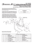
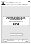
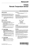
R7500C Wide Range Proportional Temperature Controller INSTALLATION INSTRUCTIONS They are fastened to the mounting surface through the two diagonally opposed mounting holes in the back of the case. See Fig. 1. For access to the mounting holes, remove the cover from the case by loosening the cover mounting screw. The mounting holes are now visible through the circuit board notches in the upper right and lower left-hand corners. Determine placement of the mounting holes in the surface and scribe the mounting hole locations. Drill pilot holes and fasten with No. 10 screws. RC186 BEFORE INSTALLATION Refer to job drawings for specific installation information and mounting location. Main and compensation sensors (when used) must be 500-ohm Balco sensors (L7022, L7025, L7033, T7506 or T7001). This controller is surface mounted through the two holes in the back of the case. Observe ambient temperature (30 to 140F) (0 to 60C) and relative humidity (5 to 95%) limitations. No special tools are required to install this controller. CAUTION: This controller requires a 11 to 12V dc power supply for proper operation. The power may be supplied by an R7503 Modutrol* Motor Converter, R7504 TwoPosition Converter, RP7505 Pneumatic Transducer, Electronic Modutrol Motors M734K or M745J, any other device designed for use with this Temperature Controller, or a separate dc power supply. This controller outputs 4 to 7 Vdc across the proportional band setting. It is designed to work with motors and actuators that expect a 4 to 7 Vdc input signal. MOUNTING This controller can be surface mounted in any convenient location such as on duct walls, end compartments of unit ventilators, etc. Copyright © 1995 Honeywell Inc. • All Rights Reserved Fig. 1. Approximate Installation Dimensions in inches (Millimeters). 95-7205 R7500C WIDE RANGE PROPORTIONAL TEMPERATURE CONTROLLER Table 1. Wire Resistance, Ohms per 1,000 Feet (304m). WIRING All wiring must agree with local electrical codes and ordinances. Wire Gage Wire Dia. Size (mm) Ohms/1000 ft (304 m) of Wire 18 1.00 6.5 Since the Controller circuits are rated NEC Class 2, some local codes allow open (no conduit) wiring. 16 1.25 4.0 14 1.60 2.6 Number 18 gage 1.0 mm insulated wire or two- or three conductor thermostat cable is acceptable for use with these Controllers, except on long sensor or remote setpoint potentiometer runs where a larger wire size should be used. See Table 1. 12 2.00 1.6 10 2.50 1.0 When determining proper wire size, remember there are two wires to the sensor and the setpoint potentiometer. Double the distance to the sensor or potentiometer to obtain the proper wire length. Calibration of the controller will be offset approximately 1F (0.5C) for every one ohm of lead wire resistance. All control wiring connections to the Controller are made to the 6-inch (152 mm), color-coded leadwires found bundled under the cover. There are two orange wires to facilitate connections to the converter and/or sensors. Crimp type connectors are recommend for field connections of the control wiring. Refer to job drawings for specific wiring information. See Figures 2 through 4 for some typical wiring diagrams. BALCO MAIN SENSOR IMPORTANT Observe color-coding of wires when making connections. M734K M745J R7503 CONVERTER BALCO MAIN SENSOR * ORANGE BLACK YELLOW VIOLET * ORANGE 14002385-008 REMOTE SETPOINT ADJUST O Y V O Y V D Z R 1 270Ω * ORN R7500 1 * ORN YEL VIO BLK R7500 POWER 3 POWER BRN 2 BROWN BALCO COMPENSATION SENSOR BALCO COMPENSATION SENSOR * BOTH ORANGE WIRES ARE ELECTICALY IDENTICAL. 1 OPTIONAL DISCHARGE COMPENSATION SENSOR. SUBSTITUTE WITH 500 OHM RESISTOR WHEN COMPENSATION IS NOT USED. C7828 CONNECT Z-D FOR DIRECT ACTION; Z-R FOR REVERSE. 2 OPTIONAL DISCHARGE COMPENSATION SENSOR. SUBSTITUTE WITH 500 OHM RESISTOR WHEN COMPENSATION IS NOT USED. 3 MOVE WIPER UP TO RAISE SETPOINT. * BOTH ORANGE WIRES ARE ELECTRICALY IDENTICAL. C7829 Fig. 2. Typical Hookup Diagram of R7500C Model with Integral Setpoint Adjustment. Fig. 3. Typical Hookup Diagram of R7500C with Remote Temperature Selector. NOTE: When the compensation sensor is not used, substitute a 500-ohm resistor and set the compensation ratio at the maximum setting (20). 95-7205 1 2 R7500C WIDE RANGE PROPORTIONAL TEMPERATURE CONTROLLER 11-12 Vdc POWER SUPPLY + – MODULTROL IV MOTOR BALCO MAIN SENSOR 1 BLACK ORANGE ORANGE YELLOW C T2 L1 8.2K T1 L2 R R7500 BROWN X-FORMER VIOLET M7186A1004 M7185G1000 2 BALCO COMPENSATION SENSOR 1 C AND T2 ARE INTERNALLY CONNECTED. AN 8.2K OHM RESISTOR IS PROVIDED INTERNALLY TO CORRECTLY LOAD THE R7500 OUTPUT. 2 OPTIONAL COMPENSATION SENSOR. SUBSTITUTE WITH 500 OHM RESISTOR WHEN COMPENSATION IS NOT USED. C7830 Fig. 4. Hookup Diagram of R7500 to Modutrol IV Motors. ADJUSTMENTS & CALIBRATION ADJUSTMENTS Set the following adjustments as specified on job drawing or as required. TEMPERATURE SETPOINT ADJUSTMENT Integral setpoint adjustment is provided on the R7500C. When it is desired to use a remote setepoint adjustment, set the integral setpoint adjustment knob to the same temperature as the top end of the remote setpoint scale. When using the 14002385-008 remote setpoint assembly, set the integral setpoint knob to REMOTE. Calibration of the remote potentiometer will then be correct. PROPORTIONAL BAND (PB) ADJUSTMENT This adjustment indicates the change in temperature required at the sensor to move the final control device (i.e., valve, damper) from one extreme position to the other (full on to full off). The controller has the highest gain with the lowest PB setting. Fig. 5. View of R7500C with Cover Removed Showing Adjustment Locations. 3 95-7205 R7500C WIDE RANGE PROPORTIONAL TEMPERATURE CONTROLLER COMPENSATION RATIO ADJUSTMENT CHECKOUT AND TESTING Compensation ratio is the number of degrees temperature change required at the compensation sensor to change the primary sensor control point one degree F. CHECKOUT The only checkout ordinarily required is to slowly rotate the Setpoint Adjustment through the total proportional band of the device to determine if the output devices operate properly. When a compensation sensor (T2) is used, the compensation ratio adjustment provides a means for adjusting the effect of the compensation sensor on the primary sensor (T1). For example, with a compensation ratio setting of 10, a 10 degree F drop in temperature at the compensation sensor is required to increase the controlled temperature 1 degree F. If the system does not function properly or the controller appears to be out of calibration, proceed with the following testing information. This adjustment has a range of 0.25 to 20. A blank table provided in the controller is for noting the compensation schedule. TESTING Before testing, be sure the Controller power supply (11 to 12 Vdc) is present at test point (+) and (–1) of R7500 models. If the correct supply voltage is not available at these points, check the power input device as indicated in the literature accompanying the applicable unit. Use the formula below to calculate the compensation ratio for hot water reset applications: Comp. Ratio = Change in outside air temp. Change in hot water temp. + P.B. NO. 1 (R1) CALIBRATION POTENTIOMETER Adding P.B. to the change in hot water temperature compensates for proportional offset. POWER SUPPLY TEST POINT (-) CALIBRATION The R7500 family of controllers are factory calibrated and checked prior to shipment and should operate satisfactorily on job startup. NO. 2 (R7) CALIBRATION POTENTIOMETER If the sensor and/or the setpoint potentiometer are a long distance from the controller, it may be necessary to recalibrate the controller. Calibration potentiometers are behind the three holes on the left side of the front panel, see Figure 6. To compensate for main sensor and/or setpoint potentiometer lead wires or calibration, adjust the middle potentiometer R7 (Cal. Pot. No. 2) clockwise. This compensates for leadwire length and a controlling temperature which is lower than the setpoint. (3.5 degrees of rotation per ohm of leadwire resistance or per degree off-calibration). POWER SUPPLY TEST POINT (+) OUTPUT VOLTAGE TEST POINT Y1 C8041 Fig. 6. Test Points and Calibration Adjustment Locations. To compensate for the compensation sensor leadwire resistance, adjust the top left potentiometer R1 (Cal. Pot. No. 1) clockwise. (3.2 degrees of rotation per ohm of leadwire resistance or per degree off-calibration.) Cal. Pot. No. 1 also can be used to vary the compensation start point (temperature at which compensation affect is zero). The factory compensation start point setting is 70F. Turning Cal. Pot. No. 1 CCW lowers the compensation start point temperature. All R7500 series of controllers include test points on the left side of the front panel (see Fig. 6). All Controllers have the following points— Y1 = Output voltage (yellow leadwire) –1 = Power supply (–), (violet leadwire) + = Power supply (+), (orange leadwire) Using the appropriate scale voltmeter, insert test probes into appropriate holes for voltage checks. 95-7205 4 R7500C WIDE RANGE PROPORTIONAL TEMPERATURE CONTROLLER NOTE: 1. 2. To ensure correct voltage readings in the following tests, a 500-ohm resistor should be substituted for the compensation sensor (if its temperature is not near 75F [24C]) and “comp. ratio” should be set at 20. If the controller output is not connected, wire a 390 ohm “load” resistor from orange to yellow wires. R7500 Adjust setpoint knob to correspond to the ambient temperature at the main sensor. Set the proportional band at 5. The output voltage between points Y1 and (+) should be approximately one-half power supply voltage minus 0.6 Vdc. If this reading is not found, the device can be recalibrated by adjusting the calibration potentiometer No. 2 (left center of panel, see Fig. 6) until this reading is reached. 5 95-7205 Home and Building Control Honeywell Inc. Honeywell Plaza P.O. Box 524 Minneapolis, MN 55408-0524 95-7205 Rev. 10-95 Printed in U.S.A. Home and Building Control Honeywell Limited-Honeywell Limitée 740 Ellesmere Road Scarborough, Ontario M1P 2V9 Helping You Control Your World QUALITY IS KEY