1
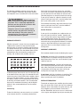
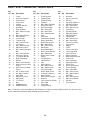
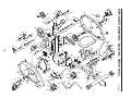
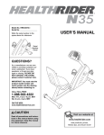
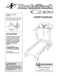
Model No. HREX1395.0
Serial No.
Serial
Number
Decal
USER’S MANUAL
QUESTIONS?
As a manufacturer, we are committed to providing complete
customer satisfaction. If you
have questions, or if parts are
damaged or missing, PLEASE
CONTACT OUR CUSTOMER
SERVICE DEPARTMENT
DIRECTLY.
CALL TOLL-FREE:
1-888-922-4222
Mon.–Fri., 6 a.m.–6 p.m. MST
ON THE WEB:
www.healthriderservice.com
CAUTION
Read all precautions and instructions in this manual before using
this equipment. Keep this manual
for future reference.
Visit our website at
www.healthrider.com
new products, prizes,
fitness tips, and much more!
TABLE OF CONTENTS
IMPORTANT PRECAUTIONS . . . . . . . . . . . . . . . . . . . . . . . . . . . . . . . . . . . . . . . . . . . . . . . . . . . . . . . . . . . . . . . .2
BEFORE YOU BEGIN . . . . . . . . . . . . . . . . . . . . . . . . . . . . . . . . . . . . . . . . . . . . . . . . . . . . . . . . . . . . . . . . . . . . . .3
ASSEMBLY . . . . . . . . . . . . . . . . . . . . . . . . . . . . . . . . . . . . . . . . . . . . . . . . . . . . . . . . . . . . . . . . . . . . . . . . . . . . . . .4
HOW TO OPERATE THE EXERCISE CYCLE . . . . . . . . . . . . . . . . . . . . . . . . . . . . . . . . . . . . . . . . . . . . . . . . . . . .8
MAINTENANCE AND TROUBLESHOOTING . . . . . . . . . . . . . . . . . . . . . . . . . . . . . . . . . . . . . . . . . . . . . . . . . . .12
CONDITIONING GUIDELINES . . . . . . . . . . . . . . . . . . . . . . . . . . . . . . . . . . . . . . . . . . . . . . . . . . . . . . . . . . . . . . .13
PART LIST . . . . . . . . . . . . . . . . . . . . . . . . . . . . . . . . . . . . . . . . . . . . . . . . . . . . . . . . . . . . . . . . . . . . . . . . . . . . . .14
EXPLODED DRAWING . . . . . . . . . . . . . . . . . . . . . . . . . . . . . . . . . . . . . . . . . . . . . . . . . . . . . . . . . . . . . . . . . . . .15
ORDERING REPLACEMENT PARTS . . . . . . . . . . . . . . . . . . . . . . . . . . . . . . . . . . . . . . . . . . . . . . . . . .Back Cover
LIMITED WARRANTY . . . . . . . . . . . . . . . . . . . . . . . . . . . . . . . . . . . . . . . . . . . . . . . . . . . . . . . . . . . . . .Back Cover
IMPORTANT PRECAUTIONS
WARNING:
To reduce the risk of serious injury, read the following important precautions before using the exercise cycle.
1. Read all instructions in this manual and all
warnings on the exercise cycle before using
the exercise cycle.
7. Keep children under the age of 12 and pets
away from the exercise cycle at all times.
8. The exercise cycle should not be used by
persons weighing more than 250 pounds.
2. Use the exercise cycle only as described in
this manual.
9. Wear appropriate clothes while exercising;
do not wear loose clothes that could become
caught on the exercise cycle. Always wear
athletic shoes for foot protection while using
the exercise cycle.
3. It is the responsibility of the owner to ensure
that all users of the exercise cycle are adequately informed of all precautions.
4. The exercise cycle is intended for home use
only. Do not use the exercise cycle in
a commercial, rental, or institutional setting.
10. The pulse sensor is not a medical device.
Various factors, including the user's movement, may affect the accuracy of heart rate
readings. The pulse sensor is intended only
as an exercise aid in determining heart rate
trends in general.
5. Keep the exercise cycle indoors, away from
moisture and dust. Place the exercise cycle
on a level surface, with a mat beneath it to
protect the floor. Make sure that there is
enough clearance around the exercise cycle
to mount, dismount, and use it.
11. Always keep your back straight when using
the exercise cycle; do not arch your back.
6. Inspect and properly tighten all parts regularly. Replace any worn parts immediately.
12. If you feel pain or dizziness while exercising,
stop immediately and cool down.
WARNING:
Before beginning this or any exercise program, consult your physician. This
is especially important for persons over the age of 35 or persons with pre-existing health problems.
Read all instructions before using. ICON assumes no responsibility for personal injury or property
damage sustained by or through the use of this product.
2
BEFORE YOU BEGIN
Thank you for selecting the new HEALTHRIDER® N25
exercise cycle. Cycling is one of the most effective
exercises for increasing cardiovascular fitness, building
endurance, and toning the body. The N25 exercise
cycle offers a selection of features designed to let you
enjoy this healthful exercise in the convenience and
privacy of your home.
model number and serial number before calling. The
model number is HREX1395.0. The serial number can
be found on a decal attached to the exercise cycle
(see the front cover of this manual for the location of
the decal).
To avoid a registration fee for any service needed
under warranty, you must register the exercise
cycle at www.healthriderservice.com/registration.
For your benefit, read this manual carefully before
you use the exercise cycle. If you have questions
after reading this manual, please see the front cover
of this manual. To help us assist you, note the product
Before reading further, please familiarize yourself with
the parts that are labeled in the drawing below.
Console
FRONT
Pedal/Strap
Wheel
Handlebar
Pulse Sensor
Adjustment Knob
Seat
RIGHT SIDE
REAR
Leveling Cap
CAUTION: The warning decal shown above has been placed on the exercise cycle in the
location shown. If the decal is missing, or if it is not legible, call the toll-free telephone number on the front of this manual and order a free replacement decal. Apply the decal in the
location shown.
3
ASSEMBLY
To hire an authorized service technician to assemble the exercise cycle, call toll-free 1-800-445-2480.
Assembly requires two persons. Place all parts of the exercise cycle in a cleared area and remove the packing materials. Do not dispose of the packing materials until assembly is completed. In addition to the included
hex keys, assembly requires a phillips screwdriver
and an adjustable wrench
.
As you assemble the exercise cycle, use the drawings below to identify small parts. The number in parentheses
below each drawing is the key number of the part, from the PART LIST on page 14. The number following the
parentheses is the quantity needed for assembly. Note: Some small parts may have been pre-assembled. If a
part is not in the parts bag, check to see if it has been pre-assembled.
M8 Nylon
Locknut (17)–2
M8 Acorn Nut
(11)–2
M8 x 16mm
Screw (62)–3
M8 Curved
Washer (107)–7
M8 x 20mm
Washer (10)–8
M8 x 70mm
Carriage Bolt (9)–2
M8 x 16mm
Bolt (87)–4
M8 x 40mm
Screw (63)–2
M8 x 80mm Hex
Bolt (40)–2
4
M4 x 12mm
Screw (106)–4
1. Insert the Seat Back Support (2) into the Seat Bracket
(3). Attach the Seat Back Support with two M8 x 80mm
Hex Bolts (40), four M8 x 20mm Washers (10), and
two M8 Nylon Locknuts (17).
1
17
2. Attach the Handlebar (7) to the Seat Bracket (3) with
two M8 x 40mm Screws (63) and two M8 Curved
Washers (107). Be careful to avoid pinching the
Pulse Wire (71).
3. Slide the Seat Frame (4) partially out of the Frame (1),
and align one of the adjustment holes in the Seat
Frame with the indicated hole in the Frame. Next,
tighten the Adjustment Knob (99) into the Frame.
Attach the Rear Stabilizer (8) to the Seat Frame (4)
with two M8 x 70mm Carriage Bolts (9), two M8
Curved Washers (107), and two M8 Acorn Nuts (11).
Note: After the exercise cycle is assembled, the position of the Seat (not shown) should be adjusted; as you
pedal, there should be a slight bend in your knees
when the pedals are in the farthest forward position. To
adjust the Seat, first turn the Adjustment Knob (99)
counterclockwise two or three turns to loosen it. Next,
lift the Knob, slide the Seat Frame (4) to the desired
position, and then release the Knob. Slide the Seat
Frame in and out slightly until the pin on the Knob
engages one of the adjustment holes in the Seat
Frame. Then, retighten the Knob.
5
10
2
40
10
3
2
63
107
107
7
71
3
3
99
Hole
4
1
11
107
11
107
8
9
4. Set the Seat Bracket (3) in the Seat Frame (4), and
align the holes. Attach the Seat Bracket with four M8 x
16mm Bolts (87) and four M8 x 20mm Washers (10).
Be careful to avoid pinching the Pulse Wire (71).
4
Connect the Pulse Wire (71) to the Lower Pulse Wire
(92).
71
10
10
87
5. While another person holds the Upright (5) near the
Frame (1), connect the Upper Wire Harness (77) to
the Lower Wire Harness (66). Next, connect the Upper
Pulse Wire (75) to the Center Pulse Wire (88). Insert
the excess wire into the Frame.
While another person holds the Console (76) near the
Console Bracket (6), feed the console wires through
the large hole in the Console Bracket. Next, connect
the console wires to the Upper Wire Harness (77) and
the Upper Pulse Wire (75). Then, insert all wires into
the top of the Upright (5).
Attach the Console (76) to the Console Bracket (6)
with four M4 x 12mm Screws (106).
6
87
10
4
92
5
5
Slide the Upright (5) onto the Frame (1). Attach the
Upright with three M8 x 16mm Screws (62) and three
M8 Curved Washers (107). Be careful to avoid
pinching the wires.
6. The Console (76) requires four “C” batteries (not
included); alkaline batteries are recommended. Insert
four batteries into the back of the Console. Make sure
that the batteries are oriented as shown by the
markings inside of the Console.
3
62
6
107
75
88
75
77
62
107
62
77
66
1
76
106
5
6
106
7. Identify the Left Pedal (98), which is marked with an
“L.” Using an adjustable wrench, firmly tighten the
Left Pedal counterclockwise into the Left Crank Arm
(94). Tighten the Right Pedal (not shown) clockwise
into the Right Crank Arm. Important: Tighten both
Pedals as firmly as possible. After using the exercise cycle for one week, retighten the Pedals. For
best performance, the Pedals must be kept tightened.
Adjust the pedal straps to the desired position by
pressing the end of each pedal strap onto the tab on
each pedal.
7
Tab
98
94
8. Make sure that all parts are properly tightened before you use the exercise cycle. Note: After assembly is
completed, some extra parts may be left over. Place a mat beneath the exercise cycle to protect the floor.
7
HOW TO OPERATE THE EXERCISE CYCLE
The advanced console offers a selection of features
designed to make your workouts more effective.
During each workout, the resistance of the pedals can
be changed with the touch of a button. As you exercise, the console will display continuous exercise feedback—you can even measure your heart rate using
the built-in handgrip pulse sensor.
HOW TO USE THE MANUAL MODE
1
2
The console also features five preset workout programs and a heart rate program. Each program automatically changes the resistance of the pedals as it
guides you through an effective workout.
Note: The console requires four “C” batteries. If
batteries have not been installed, see assembly
step 6 on page 6. If there is a sheet of clear plastic
on the face of the console, remove it.
8
Turn on the console.
To turn on the console, press any button.
Select the manual mode.
Each time the
console is turned
on, the manual
mode will be
selected. If you
have selected a
program, select
the manual mode
by pressing the Up or Down button repeatedly
until the word “Manual” appears in the display.
3
4
repeatedly until only the TIME, DIST., or CAL.
indicator appears in the display. Make sure that
the SCAN indicator does not appear.
Start your workout and adjust the resistance
of the pedals.
Press the
Program
Start/Stop button and then
begin pedaling.
As you pedal,
adjust the resistance of the
pedals as desired by pressing the Up and Down
buttons. There are eight resistance levels. Note:
After the buttons are pressed, it will take a few
seconds for the pedals to reach the selected resistance setting.
5
Follow your progress with the display.
After you start
SCAN Indicator
your workout,
you can select
a display mode.
To view all
modes, press
the Mode/Enter
button repeatedly until the
SCAN indicator appears. As you pedal, the console will display several different modes: the
elapsed time, your pedaling speed, the distance
that you have pedaled, and the approximate number of calories you have burned. In addition, the
console will display a heart symbol when you use
the handgrip pulse sensor and it detects your
pulse.
6
If desired, you can select a single mode for continuous display. Press the Mode/Enter button
9
The resistance
bar on the left
part of the display will show
the resistance
level of the pedals.
Measure your heart rate if desired.
Note: If there
are sheets of
Metal Contacts
clear plastic on
the metal contacts on the
handgrip pulse
sensor, peel off
the plastic. To
use the handgrip
pulse sensor,
place your hands on the metal contacts. Avoid
moving your hands. When your pulse is detected, the heart-shaped indicator in the display will
flash each time your heart beats. For the most
accurate heart rate reading, continue to hold the
handgrips for about 15 seconds.
When you are finished exercising, the console
will automatically turn off.
If the pedals are not moved and the console buttons are not pressed for a few minutes, the console will automatically turn off to conserve the
batteries.
HOW TO USE A WORKOUT PROGRAM
1
2
Turn on the console.
See step 1 on page 8.
Select a workout program.
4
Each time the
console is
turned on, the
manual mode
will be selected.
To select a workout program,
first make sure
that the word Stop is shown in the display. If it is
not shown, press the Program Start/Stop button
so the word Stop appears. Then, press the Up or
Down button repeatedly until the word Program
and the desired resistance profile appear in the
display.
Start the program.
To start the program, press the Program
Start/Stop button and begin pedaling. Each workout program is divided into ten periods. One resistance setting is programmed for each period. (The
same resistance setting may be programmed for
two or more consecutive periods.) Note: The
amount of time in each period depends on the
time goal that you set for the program. For example, if you set a 20-minute time goal, each period
will last for two minutes.
At the end of each period, the resistance of the
pedals will automatically change if a different
resistance setting is programmed for the next
period. Note: If the resistance level is too high or
too low, you can change the resistance level by
pressing the Up or Down button. However, when
the current period ends, the resistance level will
automatically change if a different resistance setting is programmed for the next period.
The resistance profiles across the bottom of the
display show how the resistance level will change
during the workout programs. For example, the
third profile shows that when the third program is
selected, the resistance will gradually increase
during the first half of the program and then
decrease during the last half.
3
Note: You can set one, two, three, or four goals
(or no goals). For example, if you want to set only
a time goal and a distance goal, select the number of minutes that you plan to exercise and then
press the Mode/Enter button. Next, select the distance that you plan to pedal and then press the
Mode/Enter button. Then, start the program (see
step 4).
After you have selected a workout program, press
the Mode/Enter button.
Set your workout goals.
Once you have
selected a workout program, you
will be prompted
to set workout
goals. Press the
Up and Down
buttons to select
the number of minutes that you plan to exercise,
the number of miles that you plan to pedal, the
approximate number of calories you want to burn,
and/or a target heart rate (see EXERCISE INTENSITY on page 13). After each selection, press the
Mode/Enter button.
10
5
6
7
Note: During the program, the console will display
the time remaining in the program if you have set
a time goal. If you have not set a time goal, the
time will count up in the same way that it does
when the manual mode is selected.
Follow your progress with the display.
See step 4 on page 9.
Measure your heart rate if desired.
See step 5 on page 9.
When you are finished exercising, the console
will automatically turn off.
See step 6 on page 9.
4
HOW TO USE THE HEART RATE PROGRAM
1
2
3
Turn on the console.
See step 1 on page 8.
Select the heart rate program.
Each time the
console is
turned on, the
manual mode
will be selected.
To select the
heart rate program, first make
sure that the word Stop is shown in the display. If
it is not shown, press the Program Start/Stop button so the word Stop appears. Then, press the Up
or Down button repeatedly until the heart symbol
begins to flash in the lower right part of the display. Then, press the Mode/Enter button.
Set a target heart rate.
The display will show a “P,” for Pulse. Press the
Up and Down buttons to select a target heart rate
goal (see EXERCISE INTENSITY on page 13).
Then, press the Mode/Enter button to confirm
your goal.
11
5
6
7
Hold the handgrip pulse sensor.
It is not necessary to hold the handgrip pulse sensor continuously during a heart rate program;
however, you must hold the handgrip pulse sensor frequently for the program to function properly.
Each time you hold the handgrip pulse sensor,
keep your hands on the metal contacts for at
least 30 seconds.
Start the program.
To start the program, press the Program
Start/Stop button and begin pedaling. When you
hold the handgrip pulse sensor, the console will
compare your heart rate to the current target
heart rate. If your heart rate is too far above or
below the target heart rate, the resistance of the
pedals will automatically change to keep your
heart rate near the target heart rate.
Follow your progress with the display.
See step 4 on page 9.
When you are finished exercising, the console
will automatically turn off.
See step 6 on page 9.
MAINTENANCE AND TROUBLESHOOTING
HOW TO ELIMINATE FLEXING IN THE CENTER OF
THE EXERCISE CYCLE
Inspect and properly tighten all parts of the exercise
cycle regularly. Replace any worn parts immediately.
To clean the exercise cycle, use a damp cloth and a
small amount of liquid dishwashing soap. Important:
To avoid damage to the console, keep liquids
away from the console and keep the console out
of direct sunlight.
If the exercise cycle flexes in the center during use,
turn the frame foot until the flexing motion is eliminated.
HANDGRIP PULSE SENSOR TROUBLESHOOTING
If the handgrip pulse sensor does not function properly,
see step 5 on page 9.
BATTERY REPLACEMENT
If the console display becomes dim, the batteries
should be replaced; most console problems are the
result of low batteries. To replace the batteries, see
assembly step 6 on page 6.
Frame
Foot
HOW TO LEVEL THE EXERCISE CYCLE
If the exercise
cycle rocks on
your floor during
use, turn one or
both of the leveling caps on the
rear stabilizer until
the rocking motion
is eliminated.
Leveling Caps
12
CONDITIONING GUIDELINES
The following guidelines will help you to plan your
exercise program. Remember that proper nutrition
and adequate rest are essential for successful results.
WARNING:
Before beginning
this or any exercise program, consult your
physician. This is especially important for
persons over the age of 35 or persons with
pre-existing health problems.
During the first few minutes of exercise, your body
uses easily accessible carbohydrate calories for energy. Only after the first few minutes of exercise does
your body begin to use stored fat calories for energy.
If your goal is to burn fat, adjust the intensity of your
exercise until your heart rate is near the lowest number in your training zone as you exercise.
For maximum fat burning, adjust the intensity of your
exercise until your heart rate is near the middle of
your training zone as you exercise.
The pulse sensor is not a medical device.
Various factors may affect the accuracy of
heart rate readings. The pulse sensor is
intended only as an exercise aid in determining heart rate trends in general.
Aerobic Exercise
If your goal is to strengthen your cardiovascular system, your exercise must be “aerobic.” Aerobic exercise is activity that requires large amounts of oxygen
for prolonged periods of time. This increases the
demand on the heart to pump blood to the muscles,
and on the lungs to oxygenate the blood. For aerobic
exercise, adjust the intensity of your exercise until
your heart rate is near the highest number in your
training zone.
EXERCISE INTENSITY
Whether your goal is to burn fat or to strengthen your
cardiovascular system, the key to achieving the
desired results is to exercise with the proper intensity.
The proper intensity level can be found by using your
heart rate as a guide. The chart below shows recommended heart rates for fat burning, maximum fat
burning, and cardiovascular (aerobic) exercise.
WORKOUT GUIDELINES
Each workout should include the following three parts:
A warm-up, consisting of 5 to 10 minutes of stretching
and light exercise. A proper warm-up increases your
body temperature, heart rate, and circulation in preparation for exercise.
Training zone exercise, consisting of 20 to 30 minutes of exercising with your heart rate in your training
zone. Note: During the first few weeks of your exercise program, do not keep your heart rate in your
training zone for longer than 20 minutes.
To find the proper heart rate for you, first find your age
at the bottom of the chart (ages are rounded off to the
nearest ten years). Next, find the three numbers above
your age. The three numbers are your “training zone.”
The lowest number is the recommended heart rate for
fat burning, the middle number is the recommended
heart rate for maximum fat burning, and the highest
number is the recommended heart rate for aerobic
exercise.
A cool-down, with 5 to 10 minutes of stretching. This
will increase the flexibility of your muscles and will
help to prevent post-exercise problems.
EXERCISE FREQUENCY
To maintain or improve your condition, plan three workouts each week, with at least one day of rest between
workouts. After a few months of regular exercise, you
may complete up to five workouts each week, if
desired. Remember, the key to success is make exercise a regular and enjoyable part of your everyday life.
Fat Burning
To burn fat effectively, you must exercise at a relatively low intensity level for a sustained period of time.
13
PART LIST—Model No. HREX1395.0
Key
No. Qty.
1
2
3
4
5
6
7
8
9
10
11
12
13
14
15
16
17
18
19
20
21
22
23
24
25
26
27
28
29
30
31
32
33
34
35
1
1
1
1
1
1
1
1
2
15
2
2
2
2
1
1
4
1
1
1
1
1
1
3
2
1
2
2
1
2
2
2
1
2
3
Description
Frame
Seat Back Support
Seat Bracket
Seat Frame
Upright
Console Bracket
Handlebar
Rear Stabilizer
M8 x 70mm Carriage
Bolt
M8 x 20mm Washer
M8 Acorn Nut
Leveling Cap
Transport Cap
M3 x 12mm Screw
“C” Magnet
M8 x 15mm Washer
M8 Nylon Locknut
M5 x 30mm Hex Head
Bolt
M5 x 15mm Washer
Resistance Spring
“C” Magnet Bracket
Right Pedal/Strap
M5 Nut
M10 x 14mm Washer
M10 x 16mm x 2.5mm
Spacer
M10 x 16mm x 10mm
Spacer
3/8” x 15mm Screw
3/8” Nylon Locknut
Snap Ring
M6 Nylon Locknut
M6 Eyebolt
“U” Bracket
Belt
6000ZZ Bearing
6003ZZ Bearing
Key
No. Qty.
36
37
38
39
40
41
42
43
44
45
46
47
48
49
50
51
52
53
54
55
56
57
58
59
60
61
62
63
64
65
66
67
68
69
70
71
72
73
1
1
1
1
2
1
1
4
2
6
1
1
1
1
2
1
4
2
1
1
2
1
1
1
1
1
3
2
1
1
1
2
2
2
2
1
2
1
Description
Clutch Bearing
Flywheel Axle
Flywheel Pulley
Flywheel
M8 x 80mm Hex Bolt
Resistance Cable
Resistance Motor
M6 x 15mm Bolt
M6 x 45mm Bolt
M6 x 15mm Washer
Seat
Seat Back
Seat Bracket Endcap
M10 x 35mm Bolt
M10 Nylon Locknut
M8 x 20mm Bolt
M5 x 12mm Screw
M8 Washer
Reed Switch/Wire
M12 x 16mm Washer
M3 x 10mm Bolt
M10 x 16mm x 6mm
Spacer
Tension Spring
Idler Bushing
Idler
Spring Washer
M8 x 16mm Screw
M8 x 40mm Screw
Transformer Wire
M10 x 85mm Screw
Lower Wire Harness
Nylon Washer
M10 x 19mm Washer
M10 Nut
Pulse Sensor Assembly
Pulse Wire
Foam Grip
Upright Endcap
Key
No. Qty.
74
75
76
77
78
79
80
81
82
83
84
85
86
87
88
89
90
91
92
93
94
95
96
97
98
99
100
101
102
103
104
105
106
107
#
#
4
1
1
1
2
4
4
2
1
1
2
1
6
4
1
1
1
1
1
1
1
1
2
2
1
1
1
4
1
4
4
1
4
7
2
1
R1205A
Description
Grommet
Upper Pulse Wire
Console
Upper Wire Harness
Handlebar Endcap
M5 x 15mm Bolt
M4 x 20mm Screw
Crank Ring
Left Side Shield
Right Side Shield
Side Shield Disc
Upright Ring
M5 x 8mm Screw
M8 x 16mm Bolt
Center Pulse Wire
Large Pulley
Magnet
Crank
Lower Pulse Wire
Large Snap Ring
Left Crank Arm
Right Crank Arm
M10 Flanged Locknut
Crank Cap
Left Pedal/Strap
Adjustment Knob
Frame Foot
Seat Frame Spacer
Frame Bushing
M4 x 14mm Bolt
M3 x 15mm Screw
M5 x 30mm Round
Head Bolt
M4 x 12mm Screw
M8 Curved Washer
Hex Key
User’s Manual
Note: “#” indicates a non-illustrated part. Specifications are subject to change without notice. See the back cover
of this manual for information about ordering replacement parts.
14
69
58 49
60
25
39
15
82
97
96
18
23
84
94
107 62
15
80
79
16
70
104
102
17 63
107
31
7
35
99
34
38
33
74
70
78
32
84
91
89
86 88
86 100
74
71
27
24
85
28
90
101
107
30
86
70
104
72
81
79
95
86
22
97
96
79
46
35
56
64
41
21
36
107
62
56
52
42
68
83
45
43
101 103
103
101
70
78
45
43
101
4
45
43
87 10
10 17
3
87
47
2
10
92
74
74
11
12
40
10
45 44
107
11
107
8
9
48
45
44
40
12
R1205A
98
52
20
79
106
54
19
81
66
62
1
69
65
6
107
105
80
13
14
51
53
55
59
61
53
50 24
37
17
34
14
24
25
30
29
31
26
27
35
32
13
28
93
57
68 67
50
5
67
EXPLODED DRAWING—Model No. HREX1395.0
76
75
77
73
ORDERING REPLACEMENT PARTS
To order replacement parts, please see the front cover of this manual. To help us assist you, please be prepared
to provide the following information:
• the MODEL NUMBER of the product (HREX1395.0)
• the NAME of the product (HEALTHRIDER N25 exercise cycle)
• the SERIAL NUMBER of the product (see the front cover of this manual)
• the KEY NUMBER and DESCRIPTION of the part(s) (see pages 14 and 15)
LIMITED WARRANTY
ICON Health & Fitness, Inc. (ICON), warrants this product to be free from defects in workmanship and
material, under normal use and service conditions, for a period of ninety (90) days from the date of purchase. This warranty extends only to the original purchaser. ICON's obligation under this warranty is limited to replacing or repairing, at ICON's option, the product through one of its authorized service centers.
All repairs for which warranty claims are made must be pre-authorized by ICON. If the product is shipped
to a service center, freight charges to and from the service center will be the customer’s responsibility. For
in-home service, the customer will be responsible for a minimal trip charge. This warranty does not extend
to any product or damage to a product caused by or attributable to freight damage, abuse, misuse,
improper or abnormal usage or repairs not provided by an ICON authorized service center; products used
for commercial or rental purposes; or products used as store display models. No other warranty beyond
that specifically set forth above is authorized by ICON.
ICON is not responsible or liable for indirect, special or consequential damages arising out of or in connection with the use or performance of the product or damages with respect to any economic loss, loss
of property, loss of revenues or profits, loss of enjoyment or use, costs of removal or installation or other
consequential damages of whatsoever nature. Some states do not allow the exclusion or limitation of incidental or consequential damages. Accordingly, the above limitation may not apply to you.
The warranty extended hereunder is in lieu of any and all other warranties and any implied warranties of
merchantability or fitness for a particular purpose is limited in its scope and duration to the terms set forth
herein. Some states do not allow limitations on how long an implied warranty lasts. Accordingly, the above
limitation may not apply to you.
This warranty gives you specific legal rights. You may also have other rights which vary from state to state.
ICON HEALTH & FITNESS, INC., 1500 S. 1000 W., LOGAN, UT 84321-9813
Part No. 235784 R1205A
Printed in USA © 2005 ICON IP, Inc.