1
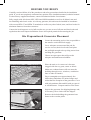
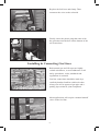
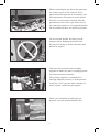
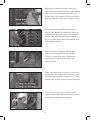
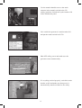
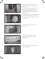
Generator
INSTALLATION
GUIDELINES
Air-Cooled Generators
Distributed Load Center Transfer Switch
OG 2697
This booklet and the accompanying video are designed to familiarize you with the installation
process for your air-cooled generator. Neither this booklet nor the accompanying video
replace or supersede any information contained in any of the written documents shipped with
your equipment. This booklet should only be used in conjunction with the Owner’s Manual,
Installation Guide and other technical documents shipped with your equipment.
Future product updates and/or modifications will be reflected in the written documentation
included with your equipment. Always read all accompanying documentation
carefully before attempting to install any generator, transfer switch or related equipment.
It is essential to comply with all regulations established by the Occupational Safety and Health
Administration (OSHA) and strict adherence to all local, state and national codes is mandatory.
Study the SAFETY RULES in the Owner’s
Manual carefully before installing,
operating or servicing any equipment. Use
this guide ONLY in conjunction with the
Owner’s Manual and Installation Guide
shipped with the generator. The generator
can operate safely, efficiently and reliably
only if it is properly installed, operated
and maintained.
your local dealer or other competent, qualified
electrician or installation technician who is
familiar with applicable codes, standards and
regulations. The operator also must comply
with all such codes, standards and regulations.
Installation, operation, servicing and repair
of this (and related) equipment must always
comply with applicable codes, standards, laws
and regulations. Adhere strictly to local, state
and national electrical and building codes.
Comply with regulations the Occupational
Safety and Health Administration (OSHA)
has established. Also, ensure that the generator
is installed, operated and serviced in accordance
with the manufacturer’s instructions and
recommendations. Following installation, do
nothing that might render the unit unsafe or
in non-compliance with the aforementioned
codes, standards, laws and regulations.
The manufacturer cannot anticipate every
possible circumstance that might involve a
hazard. The warnings in this manual, and on
tags and decals affixed to the unit are,
therefore, not all-inclusive.
Despite the safe design of this generator,
operating this equipment imprudently,
neglecting its maintenance or being careless
can cause possible injury or death.
Permit only responsible and capable persons
to install, operate or maintain this equipment.
Engine exhaust fumes contain carbon
monoxide gas, which can be DEADLY.
This dangerous gas, if breathed in sufficient
concentrations, can cause unconsciousness
or even death. For that reason, adequate
ventilation must be provided. Exhaust gases
must be piped safely away from any building or
enclosure that houses the generator to
an area where people, animals, etc., will not
be harmed.
Potentially lethal voltages are generated by
these machines. Ensure all steps are taken to
render the machine safe before attempting to
work on the generator.
General Hazards
For safety reasons, the manufacturer
recommends that this equipment be
installed, serviced and repaired by
This exhaust system must be installed
properly, in strict compliance with applicable
codes and standards.
to isolate the electrical system from the utility
distribution system when the generator is
operating. Failure to isolate the electrical
system by these means will result in damage
to the generator and may also result in injury
or death to utility workers due to backfeed of
electric energy.
Keep hands, feet, clothing, etc., away from
drive belts, fans and other moving or hot
parts. Never remove any drive belt or fan
guard while the unit is operating.
If an open bottom is used, the engine-generator
is to be installed over non-combustible
materials and should be located such that
combustible materials are not capable of
accumulating under the generator set.
Adequate, unobstructed flow of cooling and
ventilating air is critical to prevent buildup of
explosive gases and to ensure correct
generator operation. Do not alter the
installation or permit even partial blockage of
ventilation provisions, as this can seriously
affect safe operation of the generator.
Only qualified, competent installation
contractors or electricians thoroughly familiar
with applicable codes, standards and
regulations should install this standby electric
power system. The installation must comply
strictly with all codes, standards and
regulations pertaining to the installation.
Keep the area around the generator clean and
uncluttered. Remove any materials that could
become hazardous.
When working on this equipment,
remain alert at all times. Never work
on the equipment when physically or
mentally fatigued.
After the system has been installed,
do nothing that might render the
installation in non-compliance with such
codes, standards and regulations.
Generator Installation
These generators are air-cooled, enginedriven generator sets designed to supply
electric power that operates critical
electrical loads during utility power
failure. Your generator was factory-installed
in a weather resistant, all metal enclosure and
are intended for outdoor installation only.
NFPA Standards
The following published standards
booklets pertaining to standby electrical
systems are available from the National Fire
Protection Association (NFPA), Batterymarch
Park, Quincy, MA 02269:
NFPA 37, STATIONARY
COMBUSTION ENGINES AND
GAS TURBINES
Before Installation
The generator’s rated wattage/amperage
capacity must be adequate to handle all
electrical loads that the unit will power. The
critical (essential) loads may need to be
grouped together and wired into a separate
“emergency” distribution panel.
NFPA 54, NATIONAL FUEL
GAS CODE
NFPA 58, LIQUIFIED
PETROLEUM GAS CODE
NFPA 70, NATIONAL ELECTRIC
CODE (NEC)
Connecting this generator to an electrical
system, normally supplied by an electric
utility, shall be by means of a transfer switch,
NFPA 99, STANDARD FOR HEALTH
CARE FACILITIES
NFPA 101, LIFE SAFETY CODE
Grounding the Generator
NFPA 110, STANDARD FOR
EMERGENCY AND STANDBY
POWER SYSTEMS
A grounding lug is provided on the generator
mounting base for the purpose of grounding the
frame and the external electrically conductive
parts of this equipment to an approved earth
ground and/or grounding rods where required
by the National Electrical Code. Grounding
procedures must meet local regulations.
NFPA 220, STANDARD TYPES OF
BUILDING CONSTRUCTION
NOTE:
It is essential to use the latest version of any
standard to ensure that the generator and its
accessories comply with all the applicable
standards and local codes.
Battery Installation
Standby generators installed with automatic
transfer switches will crank and start
automatically when NORMAL (UTILITY)
source voltage is removed or is below an
acceptable preset level. To prevent such
automatic start-up and possible injury to
personnel, do not connect battery cables
until certain that normal source voltage at the
transfer switch is correct and the system is
ready to be placed into operation.
Other Published Standards
In addition to NFPA standards, the
following information pertaining to the
installation and use of standby electric
systems is available:
Article X, NATIONAL BUILDING CODE,
available from the American Insurance
Association, 85 John Street, New York,
NY 10038.
Storage batteries give off explosive hydrogen
gas. This gas can form an explosive mixture
around the battery for several hours after
charging. The slightest spark can ignite the
gas and cause an explosion. Such an
explosion can shatter the battery and cause
blindness or other injury. Any area that houses
a storage battery must be properly ventilated.
Do not allow smoking, open flame, sparks or
any spark producing tools or equipment near
the battery.
AGRICULTURAL WIRING
HANDBOOK, obtainable from the Food
and Energy Council, 909 University
Avenue, Columbia, MO 65201.
ASAE EP-364.2, INSTALLATION
AND MAINTENANCE OF FARM
STANDBY ELECTRIC POWER,
available from the American Society of
Agricultural Engineers, 2950 Niles Road,
St. Joseph, MI 49085.
Battery electrolyte fluid is an extremely
caustic sulfuric acid solution that can cause
severe burns. Do not permit fluid to contact
eyes, skin, clothing, painted surfaces, etc.
Wear protective goggles, protective clothing
and gloves when handling a battery. If fluid
is spilled, flush the affected area immediately
with clear water.
A52.1, AMERICAN NATIONAL
STANDARDS FOR CHIMNEYS,
FIREPLACES AND VENTING
SYSTEMS, available from the American
National Standards Institute, 1430
Broadway, New York, NY 10018.
The installer must comply with all
applicable state and local codes.
Do not dispose of the battery in a fire. The
battery is capable of exploding.
Do not open or mutilate the battery. Released
electrolyte can be toxic and harmful to the
skin and eyes.
Servicing of batteries is to be performed or
supervised by personnel knowledgeable of
batteries and the required precautions. Keep
unauthorized personnel away from batteries.
The battery represents a risk of high
short-circuit current. When working on the
battery, always remove watches, rings or
other metal objects, and only use tools that
have insulated handles.
For recommended batteries, see the
Installation Guide. All batteries must be at
100 percent state of charge before they are
installed on the generator.
When using maintenance-free batteries, it is
not necessary to check the specific gravity
or electrolyte level. Have these procedures
performed at the intervals specified in the
“Maintenance” section in the Owner’s
Manual. A negative ground system is used.
Battery connections are shown on the wiring
diagrams. Make sure all batteries are correctly
connected and terminals are tight. Observe
battery polarity when connecting batteries to
the generator set.
Vented Batteries
The electrolyte is a diluted sulfuric acid
that is harmful to the skin and eyes. It is
electrically conductive and corrosive. The
following procedures are to be observed:
Wear full eye protection and
protective clothing.
If electrolyte contacts the skin, wash it
off immediately with water.
If electrolyte contacts the eyes, flush
thoroughly and immediately with water
and seek medical attention.
NOTE:
Damage could result if the battery
connections are made in reverse.
Spilled electrolyte is to be washed down
with an acid-neutralizing agent. A common
practice is to use a solution of one pound
(500 grams) bicarbonate of soda to one gallon
(4 liters) of water. The bicarbonate of soda
solution is to be added until the evidence
of reaction (foaming) has ceased. The
resulting liquid is to be flushed with water
and the area dried.
Lead acid batteries present a risk of fire
because they generate hydrogen gas. The
following procedures are to be followed:
DO NOT SMOKE when near batteries.
DO NOT cause flame or spark in battery area.
Discharge static electricity from body
before touching batteries by first touching a
grounded metal surface.
Before You Begin
Carefully read and follow all of the procedures and safety precautions detailed in the installation
guide. If you do not completely understand any portion of the installation manual, technical manual
or other factory-supplied documents, contact an authorized dealer for assistance.
Fully comply with all relevant NEC, NFPA and OSHA standards as well as all federal, state and
local building and electric codes. As with any generator, this unit must be installed in accordance
with current NFPA 37 and NFPA 70 standards as well as any other federal, state, and local codes for
minimum distances from other structures.
Contact the local inspector or city hall to make sure you are aware of all state and local codes and
regulations that could impact installation. Secure all required permits before starting the job.
Site Preparation & Generator Placement
Locate the mounting pad as close as possible to
the transfer switch and fuel supply.
Leave adequate room around the pad for
service access (check local code) and place
the pad high enough to keep rising water from
reaching the generator.
Choose an open space that will provide
adequate and unobstructed airflow.
Place the unit so air vents won’t become
clogged with leaves, grass, snow or debris.
Make sure exhaust fumes will not enter the
building through eaves, windows, ventilation
fans or other air intakes.
Dig a rectangular area approximately five
inches deep and about six inches longer and
wider than the footprint of the generator. Cover
with polyurethane film and fill with pea gravel
or crushed stone. Compact and level the stone.
Inspect the generator for shipping damage and,
if necessary, file a claim with the shipper.
Remove the bolts holding the generator base
frame to the wooden pallet.
Make sure the lifting equipment you’ll be
using has sufficient capacity to safely handle
the weight of the generator.
Use nylon lifting straps and connect them
to the lifting eyes on each corner of the base
frame to avoid damaging the enclosure.
Set the generator onto the pad so that the
gravel bed extends several inches beyond the
generator on all sides.
Make sure the generator is level within ½ inch.
Some locations require the use of a poured
concrete mounting pad. If you’re using a
concrete pad, secure the base frame of the
generator to the pad with appropriately sized
masonry bolts or other fasteners specified by
local code.
Connect an approved ground strap to the
grounding lug on the base frame and to an
approved earth ground or grounding rod as
specified by local regulations.
Check the engine oil, and if necessary, add
enough of the recommended oil to bring the
level up to the FULL mark on the dipstick. Be
careful not to overfill the crankcase.
Converting To LP Vapor
The generator was configured for natural gas
operation at the factory. Switching over to LP
vapor is a simple procedure.
On models with the V-Twin engine, simply flip
the fuel selection switch from natural gas to LP.
On models with a single-cylinder engine, start
by making sure the battery is disconnected.
Disconnect the two wires from the solenoid and
remove the fuel hose from the outlet port.
Remove the steel plug from the number one
outlet port and the brass fitting for the fuel hose
from the number two port.
Using a quality sealant on the threaded fittings,
install the brass fitting in port one and the steel
plug in port two.
Replace the fuel hose and clamp. Then
reconnect the wires to the solenoid.
Finally, insert the plastic plug that came with
the generator into the hole on the bottom of the
air cleaner base.
Installing & Connecting Gas Lines
Both natural gas and LP vapor are highly
volatile substances, so strict adherence to all
safety procedures, codes, standards and
regulations is essential.
Gas line connections should be made by a
certified plumber familiar with local codes.
Always use AGA-approved gas pipe and a
quality pipe sealant or joint compound.
Most applications will require a manual shutoff
valve on the fuel line.
When connecting the gas line to the generator,
use a short section of UL Listed or AGAapproved flexible fuel line in accordance with
local regulations. The purpose of the flexible
fuel line is to ensure that vibration from the
generator does not cause a gas leak at one of
the connection points, so it’s important that the
line be installed with as few bends as possible.
Never bend the flexible fuel line to avoid
using an elbow. Bending the flexible line
decreases its ability to absorb vibrations and
defeats its purpose.
Check the gas pressure at the secondary
regulator to make sure there’s enough pressure
for proper generator operation.
The local gas supplier is responsible for
ensuring adequate pressure, so if the pressure
is too low, or if it’s greater than 14 inches of
water column, contact the gas supplier.
When you’ve finished checking the gas
pressure, close the manual shutoff valve.
External Electrical Connections
Drill a 1¾ inch hole and feed the conduit
through the hole.
Remove the knockout in the back of the
connection box, feed the wires through the
back of the box and secure the conduit with
the lock nut.
Seal the hole with silicone caulk. Don’t forget
to caulk the hole inside the house as well.
Mount the connection box so that it completely
covers the hole in the wall.
Connect all wires to the lugs in the connection
box (black to black, red to red and white to
white). Attach the green ground wire to the
ground screw and connect the two ends of the
four-pin plug connector.
Replace the protective cover plate …
… and lock the connection box.
10
Installing The Automatic Transfer Switch
Before beginning any installation, make sure
power is shut OFF to the main distribution
panel and carefully read the Installation Guide
that came with your transfer switch.
The distributed load center switch must be
mounted close enough to the main distribution
panel to accommodate the two-foot, pre-wired
conduit. Make sure no water or corrosive
substances can drip onto the transfer switch
enclosure.
Always inspect the switch for shipping damage.
Never mount a transfer switch that shows any
evidence of damage.
Protect against impact and mount the switch
vertically to a rigid support structure. Make
sure the switch is level and plumb.
Your transfer switch is an open transition
switch. Open transition switches prevent
electrical feedback between the generator and
the utility by only allowing load circuits to be
connected to one power supply at a time.
Each wire in the pre-wired transfer switch is
color-coded so you can easily match circuits
in the main panel to their new breakers in the
transfer switch.
11
When three-conductor wiring is used, two
120 volt circuits will often share the same neutral
wire. To avoid overloading the neutral, you
should either move BOTH of the circuits that
share the neutral or don’t move either of them.
When moving two circuits with a shared
neutral, they should be connected to adjacent
positions (one above the other) in the transfer
switch. That will assure that the two hot wires
are on separate phases and will maintain their
relationship to neutral.
Select a circuit you want to back up and
remove the power lead from the breaker.
Using UL Listed wire nuts, reconnect the
power lead to a matching breaker in the
transfer switch.
Make sure each circuit you move is protected
by the same size breaker in the transfer switch.
15 Amp circuits must be connected to 15 Amp
breakers and 20 Amp circuits to 20 Amp breakers.
For every circuit you move to the transfer
switch, connect the white neutral wire to the
neutral bar in the distribution panel.
12
Install a 2-pole breaker in the distribution panel
to protect the transfer switch. The required Amp
rating of the breaker depends on which transfer
switch you’re using, so refer to the Installation
Guide before purchasing the breaker.
Install the breaker in two adjacent empty slots
(one above the other) in the main panel.
When all emergency circuits have been moved
to the transfer switch, close the main breaker
to restore utility power and make sure utility
voltage at the transfer switch is correct. Refer
to NFPA 70E for the safety equipment required
when working inside a live transfer switch.
Before purchasing a battery for the
generator, refer to the Installation Guide for a
list of recommended batteries. Follow all of
the procedures and safety precautions in the
Installation Guide when installing the battery.
Operational Tests
Switch the generator’s main circuit
breaker OFF and put the mode switch in
the OFF position.
Make sure utility power is OFF and place all of
the emergency circuit breakers, in the transfer
switch, in the OFF position.
13
Locate the transfer handle and insert the metal
end into the slot in the main contactor
assembly. Pull the handle DOWN to move the
main contacts to the standby power
(generator) position.
NEVER OPERATE THE TRANSFER
SWITCH MANUALLY WHEN LOADS
ARE CONNECTED.
Put the generator’s mode switch in MANUAL
to start the engine.
Allow the engine to warm up, then switch the
generator’s main breaker to the ON position.
The generator is now supplying electricity to
the transfer switch but is not carrying any load.
Check to be sure that voltage and frequency
from the generator is correct. If line-to-line
voltage is not 240 volts, refer to the Installation
Guide for the proper adjustment procedures. If
line-to-neutral voltage is not 120 volts, check
the neutral connection between the generator
and transfer switch.
When finished checking the voltage, switch the
generator’s main circuit breaker OFF and put
the mode switch in the OFF position to shut
down the generator.
Make sure the 2-pole circuit breaker you
installed in the main distribution panel is in the
OFF position.
14
Use the transfer handle to move the main
contacts in the transfer switch to the UP
(utility) position. Switch the 2-pole breaker ON
in the distribution panel.
Now switch the generator’s main breaker ON
and put the mode switch in AUTO.
Shut OFF utility power and make sure the
generator starts automatically.
If everything worked properly, switch the main
breaker to ON and make sure that power is
automatically transferred back to the utility.
15
After the engine has completed its cool
down cycle and shut down, shut OFF utility
power again.
When the generator is supplying power to the
transfer switch, move the breakers in the
switch to the ON position one at a time
until the generator has accepted the entire
emergency load.
With the generator carrying the entire emergency
load, re-check gas pressure to verify that it
is at the same level it was before you started
the generator.
Switch the main breaker ON to restore
utility power.
The generator will continue running to
allow the engine to cool down before
shutting itself OFF.
Unhook the gas meter and reinstall the port
plug on the regulator.
16
Shut OFF utility power again. The generator
should start and the entire emergency load
should transfer to the generator.
Close the main breaker to restore utility power
and allow the engine to cool down and shut
itself OFF.
Setting The Automatic Exercise Function
With the mode switch in AUTO, press the
EXERCISER switch. Hold it down for at least
10 seconds and release. The generator should
start within a few seconds. The unit will run
for about 12 minutes before shutting itself
down automatically.
Once set, the generator will exercise each week
at the same time. Be sure to show the owner
how to set the exercise function on the day and
time he/she wants the unit to exercise.
If the battery is ever disconnected for any reason,
the exercise function will have to be reset.
If your generator is equipped with the low
speed exercise feature, it was enabled at the
factory and no adjustment is needed.
As you can see, this installation is not difficult.
Simply follow all of the instructions that come
with the generator and observe all safety
procedures, applicable codes and regulations.
17
Notes
18
Every installation has its own unique set of circumstances and requirements. This booklet
provides guidelines for basic installations only and is not intended to cover all applications. If
you have any questions or concerns after carefully reading all documentation received with the
equipment, contact your local dealer for assistance.
Part# 0G2697 Printed in USA 08/06
©2006 Generac Power Systems, Inc. All rights reserved.