Download Taylor 2752 weather station


Transcript
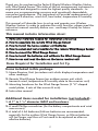
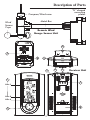
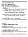
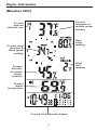
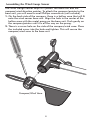
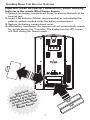
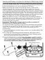
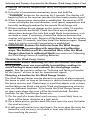
2752
Digital Wireless Weather
Station with Wind Speed Sensor
Leading the Way in Accuracy®
Instruction Manual
Thank you for purchasing the Taylor® Digital Wireless Weather Station
with Wind Speed Sensor. This state-of-the art measurement instrument is
engineered and designed to meet the highest quality standards…to
assure you uncompromising accuracy and consistently dependable,
convenient performance. This instrument will provide measurements of
wind speed & direction, wind chill, heat index, temperature & humidity.
This manual will describe how to set up and operate your Wireless
Weather System. In order to optimize the unit's function, please read this
instruction manual carefully before use…and keep it handy for future
reference.
This manual includes information about:
1.
2.
3.
4.
5.
6.
7.
Items and materials needed for installation and set up
How to assemble the remote Wind Gauge Sensor
How to install the home receiver unit batteries
How to select and test a location for the remote Wind Gauge Sensor
How to mount the Wind Gauge Sensor
How to install the batteries and calibrate the Wind Gauge Sensor
How to use and read the data on the home receiver unit
Items Required for Installation and Set Up
Items included in this package:
1. Home Receiver Unit (an indoor unit which displays temperature and
other readings)
2. Remote Wind Gauge Sensor (an outdoor sensor unit which
transmits wind, temperature & humidity data to the receiver unit)
3. Mounting hardware for the Wind Gauge Sensor (2 “U”-shaped
metal plates, 4 sets of Hex screws & nuts).
4. Instruction manual
Additional items needed for installation (not included):
1. A 1” to 1 ¼” diameter MAST and hardware
2. A small Phillips screwdriver (for the battery compartments and wind
vane screws)
3. A total of 4 AA batteries (Lithium batteries are recommended,
especially for the outdoor Wind Gauge Sensor, as lithium batteries
will last longer and thus will not need to be replaced as often as
alkaline batteries)
2
Description of Parts
“U” shaped
mounting
plates
Compass/Wind vane
Metal Bar
Wind
Sensor
Cups
Remote Wind
Gauge Sensor Unit
10
2
8
4
5
6
9
Receiver Unit
1
7
Line 1
Line 2
Line 3
8
3
3
Main Features & How to Access Functions
1 - LCD Readout (Receiver Unit):
Line 1: Displays Outdoor Temperature and Humidity, Heat Index, Wind
Chill, and Wind Speed & Direction.
Line 2: Displays indoor temperature.
Line 3: Clock displays current time and date.
2 - LED Indicator (Remote Wind Gauge Sensor):
Flashes when remote sensor transmits a reading.
3 - Multi-Function Button (Receiver Unit):
A) “CHANNEL” Button: Press to view the readings of channel 1, 2, 3 or
auto scroll (which will show each display for 10 seconds). Press
and hold 3 seconds to search for a remote sensor signal.
B) “MEMORY” Button: Press once to view maximum temperature,
humidity, heat index, and wind speed readings. Press again to
view minimum readings. Press again to return to current
readings. While the min or max reading is displayed, press and
hold for 3 seconds to clear the min or max memory.
C) “UNIT” Button: Press to toggle between wind speed measurement
displays: miles per hour (mph), kilometers per hour (km/h),
meters per second (m/s), knots, or Beaufort (bft).
D) “WIND” Button: Press to display average wind speeds and gust
wind speed.
4 – “Backlight” Button (on top of Receiver Unit):
Press to illuminate the receiver's LCD screen with an extended backlight.
5 – “Clock” button (on back of Receiver Unit):
Press and hold 3 seconds to enter Clock & Calendar Setting mode.
6 – “Up” button (on back of Receiver Unit):
Press to advance settings one step forward. Press and hold 3 seconds to
fast advance.
7 –ºF/ºC Button (on back of Receiver Unit):
Press to select °F or °C temperature scale.
8 - Battery Compartments (On back of Receiver Unit and on top
of Wind Gauge Sensor base):
The home receiver unit and remote Wind Gauge Sensor each use 2AA
batteries. Lithium batteries are recommended, especially for the outdoor
Wind Gauge Sensor, as lithium batteries will last longer and thus will not
need to be replaced as often as alkaline batteries.
9 - Wall Mount (On back of Receiver Unit):
The receiver features a recessed key hole to secure each unit to a nail or
other appropriate wall hanger.
10 - Table Stand (Fits on back of Receiver Unit):
Allows stable placement of receiver unit on a flat surface. Insert table
stand prongs into slots located at the lower back side of the receiver unit.
4
Display Information
(Receiver Unit)
Current
temperature
remote sensor
location
Current
channel
selected icon
Heat
index
reading
Current wind
direction &
Wind speed
reading
Wind
chill
reading
Current
humidity
at remote
sensor
location
Current
indoor
temperature
Current time/calendar display
5
Assembling the Wind Gauge Sensor
The Wind Gauge Sensor ships in 2 pieces: the base unit and the
compass/wind direction pointer. To attach the compass/pointer to the
base unit, you will need a small Phillips screwdriver (not included).
1. On the back side of the compass, there is a hollow area that will fit
onto the wind sensor base unit. Align the hole in the center of the
hollow area with the metal prong on the base unit. Push gently on
the compass/pointer until it is all the way on the prong.
2. There is a screw hole on the side of the compass/wind vane. Place
the included screw into the hole and tighten. This will secure the
compass/wind vane to the base unit.
Compass/Wind Vane
6
Installing Home Unit Receiver Batteries
Important: install the receiver's batteries first, before installing
batteries in the remote Wind Gauge Sensor:
1. Remove the battery compartment cover, located on the back of the
receiver unit.
2. Insert 2 AA batteries (lithium recommended) as indicated by the
polarity symbols marked inside the battery compartment.
3. Replace the battery compartment cover.
4. After battery installation, the receiver unit will automatically search
for remote sensors for 2 minutes. The displays on the LCD screen
will flash during this Search mode.
nt!
r's
orta
Imp receive re
e
o
f
h
t
e
l
b
l
,
Insta ies first teries
r
t
e
a
batt lling b Wind
insta remote or.
s
e
in th uge Sen
Ga
'
'AA
'
'AA
7
Selecting and Testing a Location for the Remote Wind Gauge Sensor
The Wind Gauge Sensor can measure temperature, relative humidity,
and wind speed and direction. It will then transmit these readings back
to the home receiver unit, up to a distance of 200 feet.
Before mounting the remote Wind Gauge Sensor, measure the
distance between the monitor and the sensor to be sure they are
within an effective transmission range (within 200 feet), and that there
are no physical obstructions between the units (such as a shed or trees)
that might block transmission signals. The Wind Gauge Sensor should
not be blocked by anything on the top or sides, so that wind can freely
reach the Sensor for accurate speed and direction reading.
Note: The effective range is vastly affected by the building materials
and where the receiver and remote units are positioned. Try various set
ups for the best results. Shorten the distance between receiver and
remote units when necessary.
Important: Though the remote unit is weather-resistant, it
should never be submerged in water.
It is recommended to perform a transmission test before permanently
mounting the remote Wind Gauge Sensor unit, in case it needs to be
moved. To test that the monitor can receive the remote sensor's
transmissions:
1. First install batteries into the home receiver unit, as described in the
previous section.
2. To install the Wind Gauge Sensor's batteries, first remove the 4
screws that secure the battery compartment cover (located on the
top of the base) and then remove the cover.
3. Insert 2 AA batteries as indicated by the polarity symbols marked
inside the battery compartment. PLEASE NOTE: Lithium batteries
are recommended, as they will last longer and thus will not
need to be replaced as often as alkaline batteries.
Wind Gauge Sensor
'
'AA
'
'AA
8
Selecting and Testing a Location for the Remote Wind Gauge Sensor Cont.
4. Replace the battery compartment cover, and replace and tighten the
screws.
5. To test for a transmission connection, press and hold the
“CHANNEL” button on the receiver for 3 seconds. The display will
begin to flash as the receiver searches for the remote sensor signal.
6. When a transmission connection is established, the receiver's LCD
screen will display the wind direction, wind speed, temperature and
humidity readings broadcast by the remote Wind Gauge unit.
7. If these readings do not appear on the receiver within 10 minutes,
the transmission has failed. Check that there are no physical
obstructions between the units that might block transmissions, such
as sheds or trees. If necessary, shorten the distance between the
receiver and remote units. Remove all the batteries from the remote,
wait at least 10 seconds, and then install the batteries again. Repeat
steps 4-6 until a successful transmission is established.
8. IMPORTANT: Remove the batteries from the Wind Gauge
Sensor before proceeding with mounting and calibration
steps. The batteries will be reinstalled later, after the Wind
Gauge's direction is calibrated North (see section on Calibrating
the Wind Gauge Sensor & Installing Batteries).
Mounting the Wind Gauge Sensor
IMPORTANT: Before mounting, be sure the receiver unit and the
wind gauge sensor are successfully transmitting readings to
avoid having to move and remount the wind gauge sensor
again. See the previous section on “Selecting and Testing a Location
for the Sensor” on how to test for transmission signals.
Choosing a Location for the Wind Gauge Sensor
The Wind Gauge Sensor may be placed in a variety of places around
the home or yard, as long as the sensor is able to transmit readings to
the home receiver unit. Please keep in mind that objects such as trees
and buildings may block wind gusts. Wind and temperature accuracy
may vary between locations. Try to locate the Wind Gauge Sensor in
an open area where the wind will be the least blocked. Possible
locations for the Wind Gauge Sensor are:
1. On the roof of a house (best wind accuracy is most likely here, as
there will be fewer obstacles at a high point).
2. On a fence post or garden shed (the more open the area, the better
the wind accuracy).
3. A soft ground location in a yard (again, the more open the area, the
better the wind accuracy, as a house or trees may block the wind
from reaching the sensor).
9
Mounting the Wind Gauge Sensor
To mount the Wind Gauge Sensor to a mast, you will need:
• A 1” to 1 ¼” diameter mast (not included).
• Hardware to fasten the mast to the mounting location (not included).
1. If necessary, mount and ground a mast at the selected location (such as a
roof or fence post) as directed in the instructions provided by the mast (not
included).
2. Hold the Sensor base up against the mast (see illustration). The metal bar
is horizontal to the mast. The Wind Vane Cups should point down, and
the Compass/Wind Direction Indicator should point up.
3. Place 2 hex screws (included) into the 2 holes on the top of the base.
4. On the bottom of the base, place one of the “U” shaped metal plates
(included) around the mast and through the screws. The mast will be
between the plate and the sensor base.
5. Tighten 2 hex nuts (included) on the screws using an Allen wrench to hold
the sensor to the mast.
6. Repeat with the bottom two holes to tightly secure the sensor to the mast.
Mounting Option: If another mast has been previously installed (for
example, for mounting an antenna), the wind gauge sensor may be mounted
on that existing mast. Or, if there is an existing piece of 1 to 1 ¼” diameter
PVC pipe or other mast that is not the correct size (such as a kitchen sink vent),
an extender may be placed on that pipe, then an extension mast may be
attached to it.
Compass/Wind
Direction Vane
Mast
Hex
Screw
“U”
Shaped
Metal
Plates
Wind Vane Cups
Hex
Screw
10
Mounting the Wind Gauge Sensor(continued)
To mount the Wind Gauge Sensor into the ground:
1. Select a location on an open, flat area of ground with the fewest
obstructions possible for best wind accuracy. Choose a spot with soft soil,
so as not to damage the mast when going into the ground, but firm
enough that the mast will not tip over after going in the ground. No
cables, pipes or other objects should be under the ground at this location.
2. Push one end of the mast slightly into the ground. Place a wood block
against the other end of the mast. Tap the block with a hammer or mallet
against the block until the mast is buried deep enough in the ground to
be stable.
3. Attach the remote Wind Gauge Sensor to the mast as previously
described.
Ground mount
Any location selected should
have the fewest obstructions
possible for best wind accuracy.
Roof mount
Antenna
mount
11
Calibrating the Wind Gauge Sensor & Installing Batteries
After mounting the Wind Gauge Sensor, the wind vane needs to be
calibrated due north so that the Sensor can properly measure the wind
direction and transmit that reading to the home receiver. Be sure the
batteries are removed from the Wind Gauge Sensor before the
calibration: Since the Sensor will orient north right after the batteries
are installed, the wind vane needs to be pointing north first, otherwise
the wind direction data transmitted to the home receiver will be
incorrect.
Important: The same Wind Direction calibration procedure (steps 2 to
5) is needed for the first set up and after every battery replacement.
1. Mount the Wind Gauge Sensor in a proper location as previously
described. If the batteries are still in the sensor, open the battery
compartment cover and remove the batteries.
2. Use the compass on the top of the Sensor to determine due north.
Turn the smaller, propeller-shaped pointer end of the Wind Direction
Indicator so it is pointing due north. Hold the Pointer facing due
north; do not allow it to turn.
North
[
Mast
3. Insert 2 AA batteries as indicated by the polarity symbols marked
inside the battery compartment. (Important: As described in Step 2,
be certain the Wind Direction Pointer on the Wind Gauge Sensor is
pointing north before inserting the batteries. Also, lithium batteries
are recommended for the Sensor, as they will last longer and thus will
not need to be replaced as often as alkaline batteries).
4. The red LED indicator above the battery cover of the Wind Gauge
Sensor will flash few seconds after battery installation, indicating
Wind Direction calibration is complete.
5. Replace the battery cover and tighten the screws.
6. If the Wind Direction Indicator is not pointing due north when the
red LED first flashes, calibration will not be accurate. Remove the
Wind Gauge Sensor batteries and repeat steps 2 - 5.
7. Hold the “CHANNEL” button on the monitor to search for remote
transmitter. If transmission is successful, readings will appear on the
receiver within 10 minutes. If readings do not appear, reorient the
units and repeat the above calibration steps.
12
Setting up Additional Temperature/Humidity Sensors (not included)
The remote Wind Gauge Sensor will transmit temperature and humidity
readings from one location. With the purchase of an additional 1 or 2
temperature/humidity sensors (not included), this Wireless Weather
System can monitor temperature and humidity readings in 1 or 2
additional locations. These remote sensors can be used to monitor
temperatures in a garage, basement, child's room, wine cellar, or any
other location within the transmission range. Please note these sensors
can only monitor temperature and humidity; wind-related readings can
only be measured by the one Wind Gauge Sensor that is
included in this package.
To purchase temperature/humidity remote sensors
(Taylor model 1438) visit www.partshelf.com.
To add a temperature/humidity Sensor (purchased separately):
1. Select a location for the remote sensor that is within the effective
transmission range.
2. Lift off the bracket stand, located on the back of the remote sensor, to
access the battery compartment cover.
3. Remove the 4 screws that secure the battery compartment cover and
then remove the cover.
4. Assign channel 2 or 3 to the remote sensor by setting the slide switch
inside the battery compartment. (Channel 1 is already assigned to the
Wind Gauge Sensor and should not be used by any other remote
sensors).
5. Insert 2 AAA alkaline batteries as indicated by the polarity symbols
marked inside the battery compartment.
6. Press and hold the “CHANNEL” button on the front of the receiver
unit to search for all remote sensor signals.
7. Press the Tx button in the remote battery compartment to send a
transmission to the receiver. The red LED Indicator light will flash
when a signal is transmitted. Remote unit temperature updates will
then be transmitted around every 35 seconds.
8. Replace the battery compartment cover, replace and tighten screws
and reattach the bracket stand.
9. When transmission connection is established, the respective
temperature and humidity of the selected remote channel will appear
on the home receiver's LCD screen. Note: If dashes are still
displayed for that channel on the receiver unit, press the Tx
button again to send another transmission.
10. Press the “CHANNEL” button to toggle between indoor and remote
sensor temperature/humidity displays.
13
How to Set the Clock and Calendar
The clock may be set to display in 12 or 24 hour format.
To set the time and date:
1. Press and hold the “CLOCK” button, located on the back of the
receiver unit. The time display will show the default year.
2. Press the “s
” button to select data in the following sequence:
Year>Month>Date>Hour>Minute>12/24 hour format>Time Offset
(Hr). (Note: Set the Time Offset to “0”.) After each selection press the
“CLOCK” button to enter.
3. Press the “CLOCK” button after the last entry to return to the time
display.
How to Read Temperatures and Other Displays
INDOOR/OUTDOOR TEMPERATURE & OUTDOOR HUMIDITY
1. The current Remote Temperature display is located at the top of the
LCD screen. The current Remote Humidity % display is in the middle
of the screen. The current Indoor Temperature is located between the
Humidity and Clock displays.
2. Press “C/F“ button on the back of the receiver to select °F or °C
temperature scale.
3. Press “CHANNEL” button to toggle between indoor, Ch1, Ch2, Ch3
or auto scroll ( ¡
) displays (if additional remote temperature /
humidity sensors are in use, purchased separately). The auto scroll
option will display the remote sensor readings for 10 seconds each.
Note: Outdoor temperature & humidity sensors are built inside the Wind
Gauge Sensor. These readings are automatically assigned to Channel 1.
Additional remote temperature/humidity sensors may be purchased
separately, and they should be assigned to Channel 2 or 3 only. See the
section on Setting up Additional Temperature/Humidity Sensors.
OUTDOOR HEAT INDEX
The Heat Index combines temperature and relative humidity for an
“apparent” temperature, or how hot the heat-humidity combination
actually feels. The Heat Index reading appears on the right side of the
LCD screen, between the Outdoor temperature and the Wind Chill
reading.
Please note: The Heat Index feature will only work for temperatures
above 57°F /14°C. Outside this range, the Heat Index will read “LL.L”.
When the temperature rises above 57ºF / 14ºC, the Heat Index will begin
to function normally again.
If more than one remote sensor is in use (up to 2 remote temperature
/humidity sensors may be purchased separately), press the “CHANNEL”
button to toggle between Ch1, Ch2, Ch3 or auto scroll ( ¡
) displays.
The auto scroll option will display the indoor readings and remote
sensor readings for 10 seconds each.
14
How to Read Temperatures and Other Displays (continued)
OUTDOOR WIND CHILL
Wind Chill combines temperature and average wind speed for an
“apparent” temperature, or how cold air on exposed skin actually feels.
The Wind Chill reading appears on the right side of the LCD screen,
below the Heat Index reading.
WIND SPEED & DIRECTION
The Wind Gauge Sensor samples the wind speed and direction and
transmits these readings to the home receiver unit. The Wind Speed &
Direction is the circular display on the left side of the LCD screen, left
of the Heat Index and Wind Chill displays.
The Wind Direction is indicated by the arrow pointer icons surrounding
the Wind Speed reading. The receiver displays 16 wind directions.
Eight of the wind directions are marked on the display: N for north, S
for south, SW for Southwest, etc. If the wind direction is between North
and Northwest, for example, the arrow will point to the dot between
the two directions.
The Wind Speed appears in the center of the arrow icons. The Wind
Speed can display in miles per hour (mph), kilometers per hour (km/h),
meters per second (m/s), Knots, or Beaufort (bft). Press the “UNIT”
button on the front of the receiver unit to change the display units.
The Wind Gauge Sensor measures both an average wind speed and
the greatest wind speed, or wind gust. The Average Wind Speed
reported is an average of wind speed over the last 2 minutes. The
Wind Gust reported is the maximum wind speed that occurred in the
last 10 minutes. Press the “WIND” button on the front of the receiver
unit to switch between Average (“AVG”) and Wind Gust (“GUST”)
displays.
MAXIMUM
/MINIMUM MEMORY
Press the “MEMORY” button on the front of the home receiver
repeatedly to view the maximum & minimum values of temperature,
humidity, heat index or wind speed readings. To clear the memory
record, press and hold the “MEMORY” button while the respective
values are displayed onscreen.
Backlight
Press the “BACKLIGHT” button for an extended green backlight to
illuminate the receiver's LCD screen for easy viewing.
15
Low Battery Warning
When the batteries on the receiver unit or the remote unit are low, the
Low Battery icon (
) will light up on receiver unit. If the batteries for
the indoor receiver are low, the Battery Icon near the indoor
temperature display will light up. If the batteries for the remote Wind
Gauge Sensor are low, the Battery Icon near the Ch 1 indicator will
light up. If there are 1 or 2 additional temperature/humidity sensors in
use (purchased separately), a Battery Icon appearing near “Ch 2” or
“Ch 3” indicates the batteries in that remote sensor are low.
Please Note: Wind direction calibration is required before battery
replacement in the Wind Gauge Sensor. See the section on
“Calibrating the Wind Gauge Sensor”.
Trouble-Shooting
Disconnected Signals
If the receiver unit does not receive a transmission from a remote unit
channel for 10 minutes, the display will show dashes. To correct this
problem:
1. Go to the remote location of that channel to check that the unit is
properly positioned, within the appropriate transmission range.
2. If new batteries are faulty on the initial installation, install fresh
batteries. If you did not notice the Low Battery icon warning and the
product performed correctly after initial set up, the batteries have
lost their charge. Replace the batteries.
3. Check to make sure the transmission path is clear of obstacles and
interference.
Note: This equipment has been tested and found to comply with the
limits for a Class B digital device, pursuant to Part 15 of the FCC Rules.
These limits are designed to provide reasonable protection against
harmful interference in a residential installation. This equipment
generates, uses, and can radiate radio frequency energy and, if not
installed and used in accordance with the instructions, may cause
harmful interference to radio communications. However, there is no
guarantee that interference will not occur in a particular installation. If
this equipment does cause harmful interference to radio or television
reception, which can be determined by turning the equipment off and
on, the user is encouraged to try to correct the interference by one or
more of the following measures:
--Reorient or relocate the receiving antenna.
--Increase the separation between the equipment and receiver.
Modifications not authorized by the manufacturer may void user's
authority to operate this device.
FCC ID: L5CW132TX-2 (wind gauge transmitter)
16
Trouble-Shooting (continued)
Transmission Collision
Signals from other household devices, such as doorbells, home security
systems and entry controls, may interfere. This is normal and does not affect
the general performance of this product. The transmission will resume once
the interference recedes.
Precautions
1. The home receiver is intended for indoor use only. It is not sealed against
moisture and could be damaged if used outdoors.
2. Do not immerse the receiver in water. If you spill liquid on it, dry
immediately with a soft, lint-free cloth.
3. The remote Wind Gauge Sensor is weather-resistant but not waterproof.
Do not immerse it in water or allow snow to accumulate on it. If this
accidentally occurs, dry it immediately with a soft, lint-free cloth.
4. Though the Remote Wind Gauge Sensor is weather-resistant, it should
not be left outdoors in extreme weather conditions. If these conditions
become likely to occur, temporarily move the transmitter to an indoor
area. Otherwise, permanent damage to the sensor's internal circuits or
external wind vane may occur.
5. Do not mount the remote Wind Gauge Sensor on a metal surface.
6. Do not subject the remote Wind Gauge Sensor to extremely severe
temperatures.
7. Do not clean either unit with abrasive or corrosive materials. This may
scratch plastic parts and corrode electronic circuits.
8. Do not subject either unit to excessive force, shock, dust, temperature or
humidity. This may result in malfunction, shorter electronic life span,
damaged battery or distorted parts.
9. Do not tamper with either unit's internal components. Doing so will
invalidate the warranty on this product and may cause damage. The unit
contains no user-serviceable parts.
10. Do not mix old and new batteries. Do not dispose of batteries in fire.
Batteries may explode or leak. Do not mix Alkaline, carbon-zinc
(standard) or Nickel-Cadmium (rechargeable) batteries. Remove the
batteries if the units will not be used for a long period of time.
11. Always read the instruction manual before operating this product.
Important: Though the remote Wind Gauge Sensor is weatherresistant, it should never be submerged in water. If extreme
weather conditions are likely to occur, temporarily move the
transmitter to an indoor area for protection. Also please note, if
using remote temperature/humidity sensors (not included), that
below 32ºF / 0ºC the LCD readout on the remote unit may begin to
fail to display. When this happens the remote will still transmit
correct temperature readings to the receiver unit but can not be
viewed at the remote location. When the temperature rises above
32ºF / 0ºC the display will begin to function normally again.
17
Specifications
Range of temperature measurement:
Receiver unit (indoor only): 32°F to 122°F (0°C to 50°C).
Remote unit: 4°F to 140°F (-20°C to 60°C).
Outdoor Humidity: 20% - 99% RH.
Wind speed range: 0 – 30m/s ~ : 0 – 108 km/h ~ : 0 – 67 mph
~ : 0 – 58.3 knot ~ : 0 - 11 Beaufort.
Transmission: Max. 200 feet (60M) open area, RF434 MHz.
Channel: 1 for Wind Gauge Sensor (included), max. 2 for remote
temperature/humidity sensors (not included).
Resolution: 0.1°F for temperature, 1% for humidity
Power: 2 AA batteries (not included) for receiver unit, lithium
recommended. 2 AA batteries (not included) for remote Wind Gauge
sensor, lithium recommended.
One Year Warranty
This product is warranted against defects in materials or workmanship
for one (1) year from date of original purchase. It does not cover
damages or wear resulting from accident, misuse, abuse, commercial
use, or unauthorized adjustment and/or repair.
Should this product require service (or replacement at our option) while
under warranty, do not return to retailer. Please pack the item carefully
and return it prepaid, along with store receipt showing date of purchase
and a note explaining reason for return to:
Taylor Precision Products
2220 Entrada Del Sol, Suite A
Las Cruces, New Mexico 88001
www.taylorusa.com
There are no express warranties except as listed above. This warranty
gives you specific legal rights, and you may have other rights which vary
from state to state.
For additional product information, or warranty information in Canada
or elsewhere outside the USA, please contact us through
www.taylorusa.com.
Made to our exact specifications in China.
© 2009 Taylor Precision Products and its affiliated companies, all rights reserved.
Taylor® and Leading the Way in Accuracy® are registered trademarks of Taylor
Precision Products and its affiliated companies. All rights reserved.
18
2752 2.09ER2